Power Automation and Protection Division
I.L. 40-201.9
REL 352 Version 1.00
3-5
3
7.2.
Single Phase-to-Ground
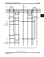
Single phase-to-ground fault detection (see Figure 3-10) is accomplished by 3 non-directional
phase units (A, B, C). Expressions 1 and 2 (below) are for the operating and reference quantity,
respectively. The unit will produce output when the operating quantity leads the reference quan-
tity.
eq. (1)
and
eq. (2)
where
V
XG
=
V
AG
, V
BG
or V
CG
I
X
=
I
A
, I
B
or I
C
I
0
=
zero sequence relay current
Z
1L
, Z
0L
=
Positive and zero sequence line impedance in relay ohms
Z
FG
=
Forward zone reach setting in secondary ohms for SLGF
Z
RG
=
Reverse reach setting in secondary ohms for SLGF
7.3.
Three-phase
Three-phase fault detection (
see Figure 3-11) is accomplished by the logic operation of one of
the three ground units, plus the 3øF output signal from the phase selector unit.
However, for a 3-phase fault condition, the computation of the distance units will be:
V
XG
- I
X
Z
P
eq. (3)
and
eq. (4)
where
V
XG
=
V
AG
, V
BG
, V
CG
I
X
=
I
A
, I
B
or I
C
Z
RG
=
Phase reach setting in secondary ohms for SLGF.
7.4.
Phase-to-Phase
The Phase-to-Phase unit (
see Figure 3-12) responds to all forward Phase-to-Phase faults, and
some phase-phase-to-ground faults. Expressions 5 and 6 are for operating and reference
V
XG
I
X
Z
0L
Z
1L
–
Z
1L
----------------------- I
0
+
Z
FG
–
j V
XG
I
X
Z
OL
Z
1L
–
Z
L
------------------------ I
0
+
Z
RG
+
j V
XG
I
X
Z
RG
+
[
]
Содержание REL 352
Страница 2: ......
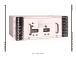
Страница 13: ...I L 40 201 9 Power Automation and Protection Division 1 6 REL 352 Version 1 00 Figure 1 1 REL 352 Front Panel ...
Страница 14: ...Power Automation and Protection Division I L 40 201 9 REL 352 Version 1 00 1 7 1 Figure 1 1a REL 352 Rear view ...
Страница 16: ......
Страница 130: ......


