Power Automation and Protection Division
I.L. 40-201.9
REL 352 Version 1.00
1-1
1
1.
INTRODUCTION
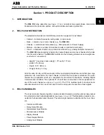
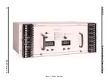
The REL 352 relay assembly (
see Figure 1-1
) is a numerical (
fully digita
l) phase comparison
transmission line protection system, with optional distance back-up protection.
2.
REL 352 CONSTRUCTION
The standard nomenclature for ABB relay protection equipment is as follows:
• Cabinet – contains fixed-racks, swing-racks, or open racks
• Rack – contains one or more chassis (e.g., the REL 352)
• Chassis – contains several modules (e.g., Microprocessor or Power Supply)
• Module – contains a number of functional circuits (on printed circuit board)
• Circuit – a complete function on a printed circuit board (e.g., analog-to-digital conversion)
• The REL 352 relay assembly consists of an outer-chassis and an inner-chassis which slides
into the outer-chassis. The REL 352 conforms to the following dimensions and weight (
also
see Section 2, subsection 6
):
• Height 7" (requires 4 rack units @ 1.75" each); 177 mm
• Width 19"; 483 mm
• Depth 13.6"; 345 mm
• Weight 38 Lbs; 17.5 kg
All of the relay circuitry, with the exception of the input isolation transformers and first-line surge
protection, are mounted on the inner chassis, to which the front panel is attached. The outer
chassis has a backplate, which is a receptacle for all external connections, including Digital
Communication Interface. Two optional FT-14 switches are mounted in the two peripheral ar-
eas of the outer chassis (
see Figure 4-1, pg. 4-12
). The FT-14 switches permit convenient and
safe disconnection of trip, ac and dc input circuits, and provide for injection of test signals.
3.
REL 352 MODULES
The inner and outer chassis, together, contain standard modules, plus the optional relay output
for extended contact output applications (
see Figure 1-2, pg. 1-8
). The Backplane module is con-
nected to the backplate (outer chassis). The remaining modules are attached to the inner chas-
sis:
• Interconnect Module
• Relay Output Module
• Optoisolated Input Module
• Microprocessor Module
• Display Module
• Power Supply Module
• Analog Input Module
Section 1. PRODUCT DESCRIPTION
Содержание REL 352
Страница 2: ......
Страница 13: ...I L 40 201 9 Power Automation and Protection Division 1 6 REL 352 Version 1 00 Figure 1 1 REL 352 Front Panel ...
Страница 14: ...Power Automation and Protection Division I L 40 201 9 REL 352 Version 1 00 1 7 1 Figure 1 1a REL 352 Rear view ...
Страница 16: ......
Страница 130: ......


