


Konserwacja i części zamienne
Maintenance
and Spare Parts
5
MNS DTR / MNS Service
69
2.
Testowanie obwodów sterowniczych za pomocą modułu
testowego
(patrz
tabela na następnej stronie)
M
oduł wysuwny powinien być wysunięty do pozycji serwisu, a moduł
testowy wetknięty do gniazda sterowniczego.
Następnie moduł wysuwny należy przesunąć z powrotem do pozycji
WYSUW i zabezpieczyć przez przekręcenie pokrętła do pozycji
WY
SUW. W tym położeniu działają tylko obwody sterownicze. W
ten sposób można testować obwody sterownicze bez załączania
obwo
dów siłowych.
Dalsze informacje zawiera poniższa tabela.
3.
Testowanie obwodów sterowniczych za pomocą kabla
testowego
Kabel testowy stosuje się w celu umożliwienia przeprowadzenia
funkcji testowych na ze
wnątrz modułu. Kabel testowy ma 3 m dłu-
gości i posiada zestaw zacisków (16, 20 lub 32 zaciski).
Dalsze informacje zawiera poniższa tabela.
Testowanie obwodów sterowniczych za pomocą modułu lub
kabla testowego
Moduł lub kabel testowy powinien być podłączony pomiędzy gniaz-
dem kontrolnym
(gniazdo żeńskie) w przedziale kablowym a gniaz-
dem kontrolnym
(męskie) w module wysuwnym.
Moduł testowy stosuje się do kontroli modułu przy jego wysunięciu o
30 mm.
Kabel testowy stosowany jest do kontroli modułu z zewnątrz.
(np. na osobnym stole do prac serwisowych).
Moduł testowy i kabel testowy dla modułów 4E dostępne są na
indywidualne zapytanie.
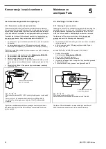
2. Testing of the control circuit with the help of a test adapter
(refer to table on the next page)
For this purpose, the withdrawable module must be pulled out to
maintenance position, and an adapter must be plugged into the
control plug.
Then the module is pushed back to ”isolating position” and
secured by turning the switch handle to isolation position. In this
position, the control circuit is operational, but the power circuit is
not. Thus, testing can be carried out without power.
For further information refer to table hereunder.
3. Testing of the control circuit with the help of a test cable
The test cable is designed for carrying out the test outside the
withdrawable module compartment. The test cables are 3 Mlong
and have 16, 20 or 32 poles.
For further information refer to the table hereunder.
Control circuit testing by means of a test adapter or a test
cable
Test adapter resp. test cable will be plugged between control plug
(female plug) in the compartment and control plug (male plug) of
the withdrawable module.
The test adapter is used for control voltage testing in the com-
partment with a 30 mm withdrawn withdrawable module.
The test cable is used for control voltage testing outside the
withdrawable module compartment (i.e. on a separate work-plate).
Test adapter and test cable for withdrawable modules size 4E and
6E on request.
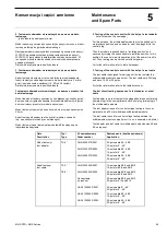
Opis
Description
Typ/
Type
Nr zamówieniowy
Order number
Zastosowanie (kostka zaciskowa)
Application
Moduł testowy/
test adapter
TA 8
°
GILN 220007 R0001
GILN 220007 R0002
GILN 220007 R0003
32-polowa dla 8E - 48E
32-pole for 8
° - 48°
16-polowa dla 8E - 48E
16-pole for 8
° - 48°
20-polowa dla 8E - 48E
20-pole for 8
° - 48°
Kabel testowy/
test cable
TK 2
°
TK 8
°
GILN 220005 R0001
GILN 220005 R0002
Na zapytanie
on request
HANL 100063 R0001
HANL 100063 R0002
HANL 100063 R0003
16-polowa dla 8E/4 und 8E/2
16-pole for 8E/4 and 8E/2
20-polowa dla 8E/4 und 8E/2
20-pole for 8E/4 and 8E/2
38-polowa dla 8E/4 und 8E/2
38-pole for 8
°/4 and 8°/2
32-polowa dla 8
° - 48°
32-pole for 8
° - 48°
16-polowa dla 8E - 48E
16-pole for 8
° - 48°
20-polowa dla 8E - 48E
20-pole for 8
° - 48°
Содержание MNS
Страница 1: ...MNS Rozdzielnica niskiego napięcia Dokumentacja Techniczno Ruchowa Service Manual ...
Страница 116: ......