


Opis techniczny
Technical Description
1
MNS DTR / MNS Service
10
1.3 System szyn
1.3 Busbar system
Stosowane s
ą następujące rodzaje systemów szyn:
szyny zbiorcze (patrz Rys. 3 i 4),
szyny dystrybucyjne (patrz Rys. 5, 6 i 7),
szyny ochronne i neutralne (PE+N/PEN) (patrz Rys. 4).
The following busbar systems can be installed:
busbars (see fig. 3 and 4),
distribution bars (see fig. 5, 6 and 7),
protective and neutral conductor bars (PE+N/PEN)
(see fig. 4).
1.3.1 Szyny zbiorcze
1.3.1 Busbars
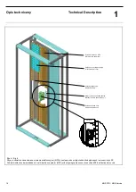
Szyny zbiorcze
znajdują się w tylnej części (przedział szynowy)
celki
i mogą być prowadzone na dwóch wysokościach:
Podwójne szyny zbiorcze znajdują się w przedziale szynowym
na górnym i dolnym poziomie.
Pojedyncze szyny zbiorcze znajdują się w przedziale szyno-
wym
na górnym lub dolnym poziomie.
W przypadku
podwójnego systemu szyn możliwa jest praca
równoległa lub szeregowa.
Zależnie od prądu znamionowego używa się 2, 4 lub 8 (2x4)
szyn na fazę.
Celki jedno- i dwustronn
e posiadają wspólny system szyn.
System szyn może być realizowany w wersji 3- lub 4-polowej.
System szyn jest podzielony na sekcje odpowiadające podziałom
transportowym rozdzielnicy.
The busbars are arranged in the rear section (busbar
compartment) of the cubicle horizontally in two selectable
levels:
Double busbar systems are located at the upper and lower
level.
Single busbar systems are located at the upper or Iower level,
as required.
For double busbar systems separate, parallel or coupled
operation is possible.
Depending on the current 2, 4 or 8 (2 x 4) conductors per
phase are used.
Cubicles for front and rear operation have a common busbar
system.
The busbar system can be realised both as 3-pole or 4-pole
version.
The busbars are divided into sections corresponding to the sizes
of the switchgear shipping units.
1.3.2 Szyny dystrybucyjne
1.3.2 Distribution bars
Zapewniają połączenie szyn zbiorczych i modułów odpływo-
wych.
W modułach stacjonarnych, wtykowych, rozłączalnych i wyj-
mowalnych szyny biegną pionowo w przedziale szynowym.
(patrz Rys. 5).
Alternatywnie
może być użyta ściana wielofunkcyjna (MFS)
(patrz Rys. 6) lub
metalowa ściana wielofunkcyjna (MSW)
(patrz Rys. 7).
Jeśli użyta jest jedna z wymienionych ścian wie-
lofunkcyjnych, to miejsca przeznaczone do wprowadzania sty-
ków modułów są osłonięte i zapewniają stopień ochrony IP20.
Moduły wysuwne są umieszczone w ścianie wielofunkcyjnej
(MFS) wykonanej z materiału izolacyjnego (stopień ochrony IP
20),
który utrzymuje je w miejscu oraz chroni przed przepię-
ciami dzięki zastosowanym osłonom szyn. Jako alternatywa
mogą one być chronione przez metalową ścianę wielofunkcyj-
ną (MSW) z osłonami (stopień ochrony IP 20).
Szyny rozdzielcze mo
gą być instalowane na całej wysokości
celki odpływowej, jednakże możliwe jest dzielenie tych szyn np.
w celu wykonania układów sprzęgłowych z użyciem modułów
wtykowych,
rozłączalnych, wyjmowalnych i wysuwnych.
W jednej celce odpływowej można zainstalować maksimum
dwa 4-polowe systemy szyn rozdzielczych dla
modułów wty-
kowych,
rozłączalnych, wyjmowalnych i wysuwnych. Przy sto-
sowaniu metalowej
ściany wielofunkcyjnej (MSW) można zain-
stalować tylko
jeden
4-polowy system szyn zbiorczych.
They provide the connection link between the busbars and the
modules.
ln the fixed, plug-in, disconnectable and railable module
design they are arranged vertically in the busbar compartment
(see fig. 5).
As an alternative the use of a multi-function separator (MFS)
(see fig. 6) or a metal separation wall (MSW) (see fig. 7) is
possible for plug-in, disconnectable- and railable modules. If
using the metal separation wall (see fig. 7) the openings for
contacting are covered by protective covers (degree of
protection IP 20).
ln the withdrawable module design they are embedded into
the multi-function separator (MFS) made of insulating material
(degree of protection lP 20) and held in place and arc prooved
covered by distribution bar covers. As an alternative they
could be covered by a metal separation wall (MSW) with
protective covers (degree of protection IP 20).
The distribution bars can be installed in one length over the
total cubicle height, however, sectionalizing is possible, e.g.
for coupling for plug-in, disconnectable, railable and
withdrawable technique.
As a maximum, two 4-poIe distribution bar systems can be
installed for plug-in, disconnectable, railable and withdrawable
technique. If using the metal separation wall (MSW) only
one
4-pole distribution bar system can be installed.
Содержание MNS
Страница 1: ...MNS Rozdzielnica niskiego napięcia Dokumentacja Techniczno Ruchowa Service Manual ...
Страница 116: ......