


Obsługa
Operation
4
MNS DTR /MNS Service
62
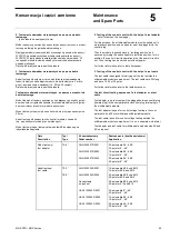
Rys. 66 / Fig. 66
Przełącznik modułu 8E/4 i 8E/2 z zaznaczonymi pozycjami pracy
Switch operating handle for withdrawable modules size 8E/4 and 8E/2
with position markers
Rys. 67 / Fig. 67
Moduł wysuwny 8E/4 z trzema kłódkami
Withdrawable module size 8E/4 with 3 padlocks
4.6 M
oduły wysuwne, rozmiar 4E do 48E
4.6 Withdrawable units size 4E up to 48E
Moduły wysuwne o rozmiarach 4E do 48E są wykonane z elementów
z blachy stalowej, które stanowią ramę nośną dla aparatów elektrycz-
nych i elementów stykowych. Dzięki zastosowaniu drzwi modułowych
możliwy jest łatwy dostęp do aparatury montowanej w module. Otwo-
rzenie drzwi
modułu wysuwnego kluczem jest możliwe tylko w pozycji
TEST lub WYLĄCZONY. Jeżeli zamontowano w module 2 zamki, to
do otwarcia drzwi w
ystarczające jest otworzenie jednego z nich.
Otwarcie
drzwi modułu w pozycji ZAŁĄCZONY możliwe jest tylko za
pomocą wkrętaka (patrz Rozdział 5, Rys. 75).
Jeżeli zostaną otwarte drzwi modułu, gdy przełącz-
nik
modułu jest w pozycji ZAŁĄCZONY, to możliwe
j
est dotkniecie elementów będących pod napię-
ciem.
Moduł wysuwny może być wyposażony w panel aparatowy wykonany
z materiału izolacyjnego służący do instalowania aparatury pomiaro-
wej i sygnalizacyjnej. Panel aparatowy przymocowany jest do mo
dułu
i wystaje
na zewnątrz przez wycięcia w drzwiach modułu. Panel ten
pozostaje na miejscu po otwarci
u drzwi. Jeżeli drzwi są otwarte, to
panel aparatowy może być odchylony w dół po uprzednim odbloko-
waniu
blokad znajdujących się z obu stron panelu aparatowego.
Dzięki temu uzyskuje się lepszy dostęp do oraz aparatury zamoco-
wanej na panelu.
Główny łącznik jest załączany przez ręczne pokrętło (przełącznik),
które spełnia rolę blokady mechanicznej i elektrycznej. Blokada elek-
tryczna wyposażona jest w dodatkowe styki (2Z + 2R).
Withdrawable units size 4E up to 48E are built-up of sheet steel
components which constitute the supporting frame for the electrical
components and the contact elements. The hinged front cover
offers the advantage of easy accessibility to the built in components
from the front side. Opening the front cover with a key is only
possible in isolated, test or OFF-position of the withdrawable unit. If
a parallel coupling is installed, opening of one lock is sufficient.
Opening of the front cover while the o
perating handle is in „ON“-
position is only possible with a screw driver (see chapter 5, fig. 75).
If opening the front cover while the operating
handle is in „ON“-position it is possible to touch
live parts.
The withdrawable unit can be equipped with an instrument panel
made of insulating material for the installation of measuring, operat-
ing and indicating instruments. The hinged instrument panel is
mounted to the withdrawable unit and sticks out through a cutout in
the front cover. This panel remains in position when the front cover
is opened. If the front cover is open, the instrument panel can be
tilted down by unlocking the locking lever on the left and right side
of the panel. After tilting down the instrument panel a better access
to the equipment both in the withdrawable unit and the instrument
panel is provided.
The main switch is operated by the operating handle which is also
used for the mechanical and the electrical interlocking. A micro
switch with maximum 2 NO and 2 NC contacts is provided for the
electrical interlocking.
Содержание MNS
Страница 1: ...MNS Rozdzielnica niskiego napięcia Dokumentacja Techniczno Ruchowa Service Manual ...
Страница 116: ......