2.3.4 Securing the base plate
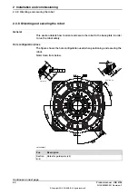
Base plate drawing
This figure shows the option base plate (dimensions in mm.)
1000
8x R65
4x R925±3
1350
±3
4x 25 ±3
M24
1350 ±3
675 ±2
24x 30
4x 250 ±5
0
0
675 ±2
15°
15°
480
480
(150,1)
225 ±3
225 ±3
A
A
C
C
B
B
D
D
C
1
A
B
D
60 ±2
610
465
320
240
4x 11°
4x
45°
4x
45°
4x
1
1°
4x
9
0°
320
610
465
240
(E)
4x 4 ±3
12x M24
A-A
3,2
0,2 A, B, C, D
0,5
18 ±1
20 ±1
4x
12 H7
+
0,018
0
1 X 45°
32 ±1
M5
B-B
0,1
(F)
xx1500000820
Common tolerance zone (accuracy all over the base plate from one contact
surface to the other).
A, B, C, D
Continues on next page
Product manual - IRB 8700
69
3HAC052853-001 Revision: F
© Copyright 2015-2018 ABB. All rights reserved.
2 Installation and commissioning
2.3.4 Securing the base plate
Содержание IRC5 Compact
Страница 1: ...ROBOTICS Product manual IRB 8700 ...
Страница 2: ...Trace back information Workspace R18 1 version a12 Checked in 2018 03 27 Skribenta version 5 2 025 ...
Страница 16: ...This page is intentionally left blank ...
Страница 824: ...This page is intentionally left blank ...
Страница 838: ...This page is intentionally left blank ...
Страница 840: ...This page is intentionally left blank ...
Страница 846: ......
Страница 847: ......


