ABB CRB 15000 Скачать руководство пользователя страница 91

3.3.10 Installation of laser scanner

Overview

The safety separation technology and speed control for CRB 15000 is based on
the connection and communication of one or two safety laser scanners in the robot.
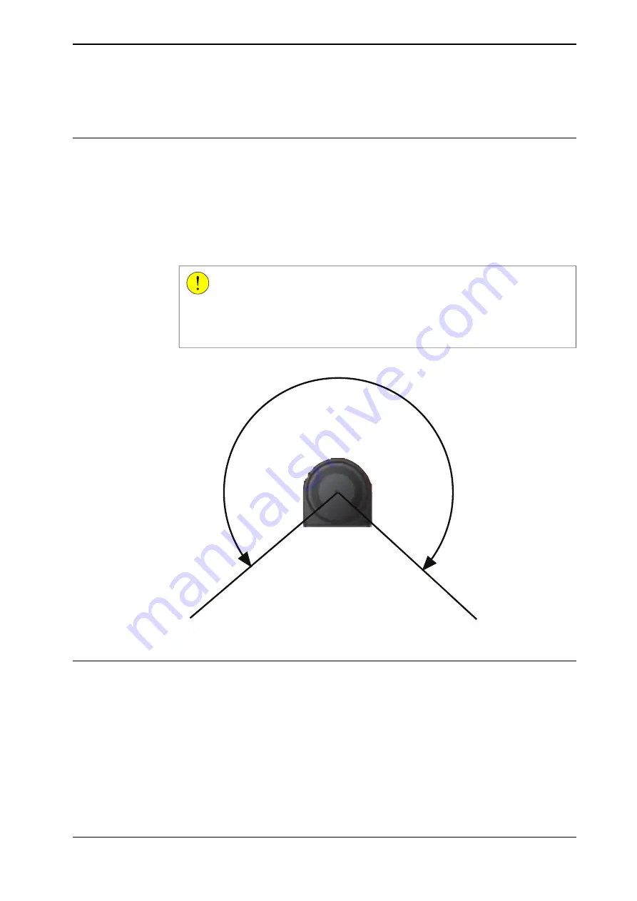
Laser scanner(s) provides a timely and continuous monitor on the activities within
its scanning area and forms a protective field. One laser scanner can provide a
scanning range of approximately 275°. The system integrator shall investigate the
site environment and place the laser scanner to a suitable location according to
the actual requirements.

CAUTION

Safety in the area that not in the scanning range must always be considered.
The system integrator shall assess the potential risks within this area and make
sure that proper measures have been applied to reduce risks.

275°

xx2100000168

Laser scanner types

The following laser scanner package options are available:

1 PROFIsafe-based laser scanner (option 3051-1 PROFIsafe scanner)

2 PROFIsafe-based laser scanners (option 3051-3 Dual PROFIsafe scanner)

1 SafetyIO-based laser scanner (option 3051-2 I/O scanner)

2 SafetyIO-based laser scanners (option 3051-4 Dual I/O scanner)

Continues on next page

Product manual - CRB 15000

91

3HAC077389-001 Revision: L

© Copyright 2021 - 2023 ABB. All rights reserved.

3 Installation and commissioning

3.3.10 Installation of laser scanner

Содержание CRB 15000

Страница 1: ...ROBOTICS Product manual CRB 15000 ...

Страница 2: ...Trace back information Workspace 23B version a17 Checked in 2023 06 29 Skribenta version 5 5 019 ...

Страница 3: ...Product manual CRB 15000 OmniCore Document ID 3HAC077389 001 Revision L Copyright 2021 2023 ABB All rights reserved Specifications subject to change without notice ...

Страница 4: ...ty by ABB for losses damage to persons or property fitness for a specific purpose or the like In no event shall ABB be liable for incidental or consequential damages arising from use of this manual and products described herein This manual and parts thereof must not be reproduced or copied without ABB s written permission Keep for future reference Additional copies of this manual may be obtained f...

Страница 5: ...2 2 Risk of tipping stability 60 3 3 On site installation 60 3 3 1 Brief installation procedure 61 3 3 2 Lifting the robot 61 3 3 2 1 Orienting and securing the robot 69 3 3 3 Manually releasing the brakes 71 3 3 4 Manually releasing the brakes with the external tool 75 3 3 5 Installation of brake release tool 77 3 3 6 Setting the system parameters for an inverted or a tilted robot 80 3 3 7 Loads ...

Страница 6: ...dule and expected component life 184 4 2 1 Specification of maintenance intervals 185 4 2 2 Maintenance schedule 186 4 3 Inspection activities 186 4 3 1 Inspecting the robot 190 4 3 2 Inspecting the cable harness 195 4 4 Cleaning activities 195 4 4 1 Cleaning the CRB 15000 196 4 5 Testing activities 196 4 5 1 Testing the brake release functionality 198 4 5 2 Running the Cyclic Brake Check routine ...

Страница 7: ...65 7 5 Drive system communication link and DC link are both down during robot running 1066 7 6 Communication failure between PROFIsafe based laser scanner PLC and controller 1067 7 7 Communication failure between PLC and controller 1069 7 8 Communication failure between scalable I O device and controller 1070 7 9 System failure when changing PROFINET based laser scanner to SafetyIO based laser sca...

Страница 8: ...This page is intentionally left blank ...

Страница 9: ...m lifting the product to its work site and securing it to the foundation to making it ready for operation maintenance work repair work decommissioning work Note It is the responsibility of the integrator to conduct a risk assessment of the final application It is the responsibility of the integrator to provide safety and user guides for the robot system Note Significant potential hazards for robot...

Страница 10: ...066553 001 Technical reference manual Event logs for RobotWare 7 Tip All documents can be found via myABB Business Portal www abb com myABB Revisions Description Revision First edition A Published in release 21B The following updates are made in this revision Added procedure for refitting the axis 4 cover in the replacement procedure for the axis 5 joint unit Changed the tightening torque for the ...

Страница 11: ...Updated information about Gleitmo treated screws see Screw joints on page 1085 Updated replacement procedures for axis 2 axis 3 axis 4 axis 5 and axis 6 cabling Information about online user guide added in section The Safe Move configurator app on FlexPendant on page 120 Added more information for laser scanners E Published in release 22B The following updates are made in this revision Corrected w...

Страница 12: ...lished in release 23A The following updates are made in this revision Updated requirement and procedure descriptions for manually releasing the brakes K Published in release 23B The following updates are made in this revision Added new variants CRB 15000 10 1 52 and CRB 15000 12 1 27 Added pin assignment on XG1 connector of SafetyIO based laser scanner Updated the logical expressions for SafeMove ...

Страница 13: ...on Troubleshooting Decommissioning Reference information safety standards unit conversions screw joints lists of tools Spare parts list with corresponding figures or references to separate spare parts lists References to circuit diagrams Technical reference manuals The technical reference manuals describe reference information for robotics products for example lubrication the RAPID language and sy...

Страница 14: ...dling of the products The manuals are aimed at those having first hand operational contact with the product that is production cell operators programmers and troubleshooters 14 Product manual CRB 15000 3HAC077389 001 Revision L Copyright 2021 2023 ABB All rights reserved Product documentation Continued ...

Страница 15: ...include specific safety information when dangerous steps are to be performed Read more in the chapter Safety on page 17 Illustrations The product is illustrated with general figures that does not take painting or protection type in consideration Likewise certain work methods or general information that is valid for several product models can be illustrated with illustrations that show a different ...

Страница 16: ...This page is intentionally left blank ...

Страница 17: ...nce Operation of the robot when the safety devices are defective not in their intended location or in any other way not working When instructions for operation and maintenance are not followed as intended Non authorized design modifications of the robot Repairs on the robot and its spare parts carried out by in experienced or non qualified personnel Foreign objects Force majeure Intended use The A...

Страница 18: ...el attached Then the integrator must clearly mark an observed symbol on the controller to avoid incorrect connections For more information see Product manual OmniCore C30 Spare parts and equipment ABB supplies original spare parts and equipment which have been tested and approved for their intended use The installation and or use of non original spare parts and equipment can negatively affect the ...

Страница 19: ...e not allowed to install maintain service repair or use the robot The plant liable must make sure that the personnel is trained on the robot and on responding to emergency or abnormal situations Personal protective equipment Use personal protective equipment as stated in the instructions Risk of entanglement Loose clothing should not be worn and long hair should be tied up to reduce the risk for e...

Страница 20: ...d will result in ser ious injury DANGER Signal word used to indicate a potentially hazardous situation which if not avoided could result in serious injury WARNING Signal word used to indicate a potentially hazardous situation related to electrical hazards which if not avoided could result in serious injury ELECTRICAL SHOCK Signal word used to indicate a potentially hazardous situation which if not...

Страница 21: ...d to indicate where to find additional information or how to do an operation in an easier way TIP Product manual CRB 15000 21 3HAC077389 001 Revision L Copyright 2021 2023 ABB All rights reserved 1 Safety 1 2 1 Safety signals in the manual Continued ...

Страница 22: ...iption Symbol Warning xx0900000812 Warns that an accident may occur if the instructions are not followed that can lead to serious injury possibly fatal and or great damage to the product It applies to warnings that apply to danger with for example contact with high voltage electrical units explosion or fire risk risk of poisonous gases risk of crushing impact fall from height etc Caution xx0900000...

Страница 23: ...Disassembling this part can cause injury Extended rotation xx0900000814 This axis has extended rotation working area compared to standard Brake release xx0900000808 Using the brake release tool will release the brakes This means that the robot arm can fall down Continues on next page Product manual CRB 15000 23 3HAC077389 001 Revision L Copyright 2021 2023 ABB All rights reserved 1 Safety 1 2 2 Sa...

Страница 24: ...over if the bolts are not securely fastened xx1500002402 Crush xx0900000817 Risk of crush injuries Continues on next page 24 Product manual CRB 15000 3HAC077389 001 Revision L Copyright 2021 2023 ABB All rights reserved 1 Safety 1 2 2 Safety symbols on manipulator labels Continued ...

Страница 25: ...087 Moving robot 1 2 3 4 5 6 xx0900000819 The robot can move unexpectedly xx1000001141 1 2 3 4 xx1500002616 Lifting bolt xx0900000821 Continues on next page Product manual CRB 15000 25 3HAC077389 001 Revision L Copyright 2021 2023 ABB All rights reserved 1 Safety 1 2 2 Safety symbols on manipulator labels Continued ...

Страница 26: ...t allowed Mechanical stop xx0900000824 No mechanical stop xx1000001144 Stored energy xx0900000825 Warns that this part contains stored energy Used in combination with Do not disassemble symbol Continues on next page 26 Product manual CRB 15000 3HAC077389 001 Revision L Copyright 2021 2023 ABB All rights reserved 1 Safety 1 2 2 Safety symbols on manipulator labels Continued ...

Страница 27: ... level Shut off with handle xx0900000827 Use the power switch on the controller Do not step xx1400002648 Warns that stepping on these parts can cause damage to the parts Product manual CRB 15000 27 3HAC077389 001 Revision L Copyright 2021 2023 ABB All rights reserved 1 Safety 1 2 2 Safety symbols on manipulator labels Continued ...

Страница 28: ...opping distances no variation of brake friction coefficient Stopping using the motor produces the shortest stopping distance without any risk of overloading structural components pre defined braking torque no delay Stopping using the motor saves on brake wear so that the brake can perform its primary holding function for longer An off path category 1 stop is best suited to Power and Force Limiting...

Страница 29: ...ification of allergenic materials in the product if any Securing the robot to the foundation The robot must be properly fixed to its foundation support as described in the respective product manual When the robot is installed at a height hanging or other than mounted directly on the floor there will be additional hazards Electrical safety Incoming mains must be installed to fulfill national regula...

Страница 30: ...for the user of the robot to operate it in a safe way setting up the necessary safety configurations and ensure that appropriate risk reduction measures are implemented See sections Working closely with the robot in a safe way on page 111 and The SafeMove configurator app on FlexPendant on page120 as well as Guidelines for transient and quasi static contact CRB 15000 on page 132 for details on how...

Страница 31: ...mperatures shall be verified when running demanding motion cycles at high ambient temperatures If necessary to prevent burns allow touch surfaces to cool down before working closely with the robot The following figure takes the CRB 15000 12 1 27 as an example to show the locations of touch surfaces All the other surfaces are considered as non touch surfaces xx2300000975 Wrist housing A Axis 5 cove...

Страница 32: ... side interface C Tubular D Tubular covers E Housing cover F 32 Product manual CRB 15000 3HAC077389 001 Revision L Copyright 2021 2023 ABB All rights reserved 1 Safety 1 5 Safety during operation Continued ...

Страница 33: ...lergic reaction Elimination Action Description Warning Make sure that protective gear like goggles and gloves are al ways worn When working with lubricants there is a risk of an allergic reac tion Allergic reaction Gearbox lubricants oil or grease When handling oil grease or other chemical substances the safety information of the respective manufacturer must be observed Note Take special care when...

Страница 34: ...ption How to release the brakes is described in the section Manually releasing the brakes on page 69 34 Product manual CRB 15000 3HAC077389 001 Revision L Copyright 2021 2023 ABB All rights reserved 1 Safety 1 6 2 Emergency release of the robot axes ...

Страница 35: ...Switch the motor to the MOTORS OFF 3 Inspect and verify that the axis maintains its position If the manipulator does not change position as the motors are switched off then the brake function is adequate Note It is recommended to run the service routine BrakeCheck as part of the regular maintenance see the operating manual for the robot controller For robots with the option SafeMove the Cyclic Bra...

Страница 36: ...y time DANGER Troubleshooting on the controller while powered on must be performed by personnel trained by ABB or by ABB field engineers A risk assessment must be done to address both robot and robot system specific hazards Related information See also the safety information related to installation operation maintenance and repair 36 Product manual CRB 15000 3HAC077389 001 Revision L Copyright 202...

Страница 37: ...ning on page 1077 If the robot is decommissioned for storage take extra precaution to reset safety devices to delivery status Product manual CRB 15000 37 3HAC077389 001 Revision L Copyright 2021 2023 ABB All rights reserved 1 Safety 1 8 Safety during decommissioning ...

Страница 38: ...This page is intentionally left blank ...

Страница 39: ...e C30 controller with Drive system 7 and the CRB 15000 10 1 52 and CRB 15000 12 1 27 can only be used with the ABB OmniCore C30 controller with Drive system 10 The drive system that a controller installed with can be distinguished by the Drive label attached on the controller cabinet Always verify the Drive label before connecting the controller to the manipulator Controllers delivered in RobotWar...

Страница 40: ... manipulator Installation angle Mounting position 0 Floor mounted Any angle Wall mounted 180 Suspended Note The actual mounting angle must always be configured in the system parameters otherwise the performance and lifetime is affected See Setting the system parameters for an inverted or a tilted robot on page 77 Loads on foundation robot The illustration shows the directions of the robots stress ...

Страница 41: ...ever reach their maximum at the same time WARNING The robot installation is restricted to the mounting options given in following load table s Floor mounted Maximum load emergency stop Endurance load in operation Force 1113 Ni 1460 Nii 1450 Niii 303 Ni 470 Nii 470 Niii Force xy 280 857 Ni 500 650 Nii 480 690 Niii 280 147 Ni 500 410 Nii 480 420 Niii Force z 711 Nmi 1 280 Nmii 1 180 Nmiii 246 Nmi 57...

Страница 42: ... 22Hz Note It may affect the ma nipulator lifetime to have a lower reson ance frequency than recommended Minimum resonance frequency Due to foundation stiffness consider robot mass including equipment i For information about compensating for foundation flexibility see the description of Motion Process Mode in the manual that de scribes the controller software option see References on page 10 150 M...

Страница 43: ...e a warm up phase recommended to be run with the robot Otherwise there is a risk that the robot stops or run with lower performance due to temperature dependent oil and grease viscosity ii Valid for CRB 15000 5 0 95 iii Valid for CRB 15000 10 1 52 and CRB 15000 12 1 27 iv Depending on climate and robot running conditions condensation may occur on the inside of plastic covers The condensation will ...

Страница 44: ...ppb Nitrogen dioxide NO2 1 250 ppb Chlorine Cl2 10 ppb Sulphur dioxide SO2 300 ppb Environmental information The product complies with IEC 63000 Technical documentation for the assessment of electrical and electronic products with respect to the restriction of hazardous substances Joint torques In collaborative applications the joint torque must be considered in the risk assessment The following t...

Страница 45: ...ety category 3 with performance level PL d according to EN ISO 13849 1 2015 and thus fulfils the safety performance requirement of the robot safety standard EN ISO 10218 1 2011 Safety data for SafeMove function OmniCore C30 for CRB 15000 Equiv PFHD incl brake i 1 hour PL PFHD SRP CS 1 hour Category SRP CS SafeMove functions 3 70x10 7 d 2 22x10 7 3 Enabling function 1 3 79x10 7 d 2 31x10 7 3 Emerge...

Страница 46: ...c Brake Check routine on page 198 Note For the manipulator all the safety functionality is included in the joint units These are only designed to be replaced as complete units see section Repair on page 201 Individual subcomponents shall not be exchanged The maximum communication and manipulator reaction times must be added to the reaction times from SafeMove see Application manual Functional safe...

Страница 47: ...rsection point of axes 4 5 6 and angle of axes 2 and 3 Angle degrees Positions at wrist center mm Position in the figure axis 5 axis 3 axis 2 Z X 0 0 0 899 470 pos0 0 68 0 1216 0 pos1 0 68 90 265 951 pos2 0 68 180 686 0 pos3 0 68 90 265 951 pos4 0 22 180 179 507 pos5 0 85 180 272 7 230 2 pos6 0 158 180 179 507 pos7 0 225 180 287 6 198 1 pos8 Continues on next page Product manual CRB 15000 47 3HAC0...

Страница 48: ...t center and angle of axes 2 and 3 Angle degrees Positions at wrist center mm Position in the figure axis 3 axis 2 Z X 0 0 1297 888 pos0 80 2 0 1882 3 150 pos1 80 2 90 400 1632 3 pos2 80 2 180 1082 3 150 pos3 80 2 90 400 1332 3 pos4 9 8 180 307 625 3 pos5 85 180 442 6 48 pos6 170 2 180 307 925 3 pos7 225 180 326 5 596 9 pos8 Continues on next page 48 Product manual CRB 15000 3HAC077389 001 Revisio...

Страница 49: ...nter and angle of axes 2 and 3 Angle degrees Positions at wrist center mm Position in the figure axis 3 axis 2 Z X 0 0 1235 635 pos0 78 4 0 1719 0 pos1 78 4 90 338 1381 pos2 78 4 180 1043 0 pos3 78 4 90 338 1381 pos4 11 6 180 369 674 pos5 85 180 276 8 193 pos6 168 4 180 369 674 pos7 225 180 194 370 6 pos8 Continues on next page Product manual CRB 15000 49 3HAC077389 001 Revision L Copyright 2021 2...

Страница 50: ...15000 5 0 95 R951 R199 4 R173 1 180 180 Y X xx2100000122 Continues on next page 50 Product manual CRB 15000 3HAC077389 001 Revision L Copyright 2021 2023 ABB All rights reserved 2 Manipulator description 2 4 Working range Continued ...

Страница 51: ...632 3 180 180 R352 6 R296 3 A X Y xx2300000577 Continues on next page Product manual CRB 15000 51 3HAC077389 001 Revision L Copyright 2021 2023 ABB All rights reserved 2 Manipulator description 2 4 Working range Continued ...

Страница 52: ...rea for axis 1 that depends on payload and the positions of other axes Simulation in RobotStudio is recom mended 180 Axis 1 180 Axis 2 225 85 Axis 3 180 Axis 4 180 Axis 5 270 Axis 6 52 Product manual CRB 15000 3HAC077389 001 Revision L Copyright 2021 2023 ABB All rights reserved 2 Manipulator description 2 4 Working range Continued ...

Страница 53: ...roy sensitive electronics Safe handling Use one of the following alternatives Use a wrist strap Wrist straps must be tested frequently to ensure that they are not damaged and are operating correctly Use an ESD protective floor mat The mat must be grounded through a current limiting resistor Use a dissipative table mat The mat should provide a controlled discharge of static voltages and must be gro...

Страница 54: ...This page is intentionally left blank ...

Страница 55: ...efore any installation work is commenced all safety information must be observed There are general safety aspects that must be read through as well as more specific safety information that describes the danger and safety risks when performing the procedures Read the chapter Safety on page17 before performing any installation work Note Always connect the CRB 15000 and the robot to protective earth ...

Страница 56: ...fting accessory used if required is suitable to handle the weight of the robot as specified in Weight robot on page 40 5 If the robot is not installed directly it must be stored as described in Storage condi tions robot on page 43 6 Make sure that the expected operating environment of the robot conforms to the specifications as described in Operating conditions robot on page 43 7 Before taking the...

Страница 57: ...ation directly store it in the delivery package Do not change the robot position before securing it to the foundation Transportation and shipping position The figures show the robot in its shipping position which also is a recommended transportation position CRB 15000 5 0 95 xx2100000115 0 Axis 1 0 Axis 2 85 Axis 3 0 Axis 4 0 Axis 5 0 Axis 6 Continues on next page Product manual CRB 15000 57 3HAC0...

Страница 58: ...5 Axis 2 225 Axis 3 0 Axis 4 30 Axis 5 0 Axis 6 Continues on next page 58 Product manual CRB 15000 3HAC077389 001 Revision L Copyright 2021 2023 ABB All rights reserved 3 Installation and commissioning 3 2 2 Risk of tipping stability Continued ...

Страница 59: ...4 15 Axis 5 0 Axis 6 WARNING The robot is mechanically unstable if not secured to the foundation Product manual CRB 15000 59 3HAC077389 001 Revision L Copyright 2021 2023 ABB All rights reserved 3 Installation and commissioning 3 2 2 Risk of tipping stability Continued ...

Страница 60: ...anipulator to the controller 4 See Product manual OmniCore C30 Configure the safety settings 5 See Product manual OmniCore C30 How to start and run the robot is described in the product manual for the controller 6 Install required equipment if any Installation of brake release tool on page75 7 DANGER Make sure all safety requirements are met when performing the first test run See Test run after in...

Страница 61: ...ower during lifting and securing it to the foundation Attachment screws The table below specifies the type of securing screws and washers to be used for securing the robot to the base plate foundation All hardware is enclosed in the robot delivery M10x35 Suitable screws 4 pcs Quantity 8 8 Quality 23 10 5 2 5 mm Steel Suitable washer DIN6325 hardened steel Ø6x24 mm 2 pcs Guide pins 32 Nm 10 Tighten...

Страница 62: ... 8 4x 12 56 73 56 73 C D 6 H7 0 012 0 7 5 6 4 6 0 0 1 8 0 2 6 4 xx2000002366 Circular hole for locating pin C Elongated hole for locating pin D Continues on next page 62 Product manual CRB 15000 3HAC077389 001 Revision L Copyright 2021 2023 ABB All rights reserved 3 Installation and commissioning 3 3 2 1 Orienting and securing the robot Continued ...

Страница 63: ...2 C D B B 6 H7 0 012 0 7 5 6 4 C 6 0 0 1 8 0 6 4 2 D xx2300000382 Circular hole for locating pin C Elongated hole for locating pin D Continues on next page Product manual CRB 15000 63 3HAC077389 001 Revision L Copyright 2021 2023 ABB All rights reserved 3 Installation and commissioning 3 3 2 1 Orienting and securing the robot Continued ...

Страница 64: ... Lifting and securing the robot Use this procedure to lift and secure the robot to its foundation Preparations of the installation site Note Action Make sure the installation site for the robot con forms to the specifications in section Technical data on page 40 1 Continues on next page 64 Product manual CRB 15000 3HAC077389 001 Revision L Copyright 2021 2023 ABB All rights reserved 3 Installation...

Страница 65: ...om the transportation package 2 Carry the robot to the installation site CAUTION Do not leave the robot standing unfastened to the foundation it is not stable on its own 3 Centering pins DIN6325 hardened steel Ø6x24 mm 2 pcs Fit two pins to the holes in the base 4 Screws M10x35 4 pcs quality 8 8 Raise the robot to standing and secure to foundation paying attention to the centering holes at the bot...

Страница 66: ...ition for transportation and lifting WARNING The robot is mechanically unstable if not se cured to the foundation 1 CAUTION The weight of the CRB 15000 robot is up to 51 kg All lifting accessories used must be sized ac cordingly 2 Continues on next page 66 Product manual CRB 15000 3HAC077389 001 Revision L Copyright 2021 2023 ABB All rights reserved 3 Installation and commissioning 3 3 2 1 Orienti...

Страница 67: ...RB 15000 12 1 27 xx2300000385 WARNING Personnel must not under any circumstances be present under the suspended load 4 Raise the overhead crane to lift the robot 5 Continues on next page Product manual CRB 15000 67 3HAC077389 001 Revision L Copyright 2021 2023 ABB All rights reserved 3 Installation and commissioning 3 3 2 1 Orienting and securing the robot Continued ...

Страница 68: ...bot gently using the attachment screws while lowering it into its mounting pos ition 8 Screws M10x35 4 pcs quality 8 8 Fit the securing screws and washers in the at tachment holes of the base 9 Washers 23 10 5 2 5 mm Steel Tightening torque 32 Nm 10 Tighten the bolts in a crosswise pattern to en sure that the base is not distorted 10 68 Product manual CRB 15000 3HAC077389 001 Revision L Copyright ...

Страница 69: ...ION At least two persons should be present when releasing the brakes Releasing the brakes from the FlexPendant Use this procedure to release the holding brakes using the FlexPendant Note The manipulator needs to be powered and motors in state Motors OFF Note Action Press the emergency stop 1 On the FlexPendant a tab appears Brake Release See Arm side interface on page 105 Open the brake release wi...

Страница 70: ...ion 5 When the enabling device is re leased or pressed fully in then the brakes are activated immediately To continue moving the arm freely the brake release function must be restarted The brake will function again as soon as the en abling device is released 6 70 Product manual CRB 15000 3HAC077389 001 Revision L Copyright 2021 2023 ABB All rights reserved 3 Installation and commissioning 3 3 3 Ma...

Страница 71: ... in section Manually releasing the brakes on page 69 CAUTION At least two persons should be present when releasing the brakes Required equipment Note Article number Equipment For releasing the holding brakes of a joint unit motor if the Robot Ware version is 7 8 or older Note The spare parts related to the brake release function using the external tool are discontinued from Q2 2023 3HAC079146 001 ...

Страница 72: ...stead xx2000002540 xx2000002539 Releasing the brakes This procedure describes how to release the holding brakes using the brake release tool Note The manipulator needs to be powered and motors in state Motors OFF Do not release the brakes in automatic operating mode Continues on next page 72 Product manual CRB 15000 3HAC077389 001 Revision L Copyright 2021 2023 ABB All rights reserved 3 Installati...

Страница 73: ... release tool against the small round recess at the axis The brake will function again as soon as the tool is removed 3 The sensor behind the cover is triggered by the tool magnet and the corresponding motor holding brake will be released If any faulty functionality is dis covered see Brake release tool does not work on page 1063 Put back the tool in its holder and store on specified location clos...

Страница 74: ...ction CAUTION Incorrect connections such as supplying power to the wrong pin may cause damage to the electrical components 1 48VDC A 0V B xx2100000124 Supply 0V on pin B and 48VDC on pin A 2 74 Product manual CRB 15000 3HAC077389 001 Revision L Copyright 2021 2023 ABB All rights reserved 3 Installation and commissioning 3 3 4 Manually releasing the brakes with the external tool Continued ...

Страница 75: ...later the tool does not work How to release the brakes using the FlexPendant is described in section Manually releasing the brakes on page 69 xx2000002541 Specify storage location The brake release tool must be mounted or permanently stored close to the robot for easy and quick access in case of emergency The storage location must be well known for all personnel working with or nearby the robot Co...

Страница 76: ...ng with screws xx2100000403 Securing with cable ties xx2100000404 76 Product manual CRB 15000 3HAC077389 001 Revision L Copyright 2021 2023 ABB All rights reserved 3 Installation and commissioning 3 3 5 Installation of brake release tool Continued ...

Страница 77: ...on of the mounting angle will result in Overloading the mechanical structure Lower path performance and path accuracy Some functions will not work properly for example Load Identification and Collision detection Gravity Beta When the robot is mounted other than floor standing rotated around the y axis the robot base frame and the system parameter Gravity Beta must be redefined If the robot is moun...

Страница 78: ... motion Mounting angles and values The parameter Gravity Beta or Gravity Alpha specifies the mounting angle of the robot in radians It is calculated in the following way Gravity Beta A x 3 141593 180 B radians where A is the mounting angle in degrees and B is the mounting angle in radians Gravity Beta Mounting angle A Example of position 0 000000 Default 0 Floor mounted 1 570796 90 Wall mounted 3 ...

Страница 79: ...stem parameters in RobotWare The value of the system parameters that define the mounting angle must be redefined when changing the mounting angle of the robot The parameters belong to the type Robot in the topic Motion The system parameters are described in Technical reference manual System parameters The system parameters are configured in RobotStudio or on the FlexPendant Product manual CRB 1500...

Страница 80: ...s or major damage to the robot Load diagrams permitted extra loads equipment and their positions are specified in the product specification The loads must be defined in the software Stopping time and braking distances The performance of the motor brake depends on if there are any loads attached to the robot See the product specification for the robot listed in References on page 10 80 Product manu...

Страница 81: ...hat is permitted on the tool flange Robot dimensions The figure shows the dimension of the robot CRB 15000 5 0 95 265 444 110 470 101 80 xx2000002368 Continues on next page Product manual CRB 15000 81 3HAC077389 001 Revision L Copyright 2021 2023 ABB All rights reserved 3 Installation and commissioning 3 3 8 Fitting equipment on the robot robot dimensions ...

Страница 82: ...0 150 787 888 xx2300000646 Continues on next page 82 Product manual CRB 15000 3HAC077389 001 Revision L Copyright 2021 2023 ABB All rights reserved 3 Installation and commissioning 3 3 8 Fitting equipment on the robot robot dimensions Continued ...

Страница 83: ... xx2300000647 Continues on next page Product manual CRB 15000 83 3HAC077389 001 Revision L Copyright 2021 2023 ABB All rights reserved 3 Installation and commissioning 3 3 8 Fitting equipment on the robot robot dimensions Continued ...

Страница 84: ...he hex spacers or fitted equipment must be taken into consideration Note If the gasket screws on the upper arm cover of CRB 15000 5 0 95 are replaced with hex spacers then the IP54 is no longer fulfilled Before fitting equipment to the robot upper arm special considerations must be taken Any external cable routing along the robot arm shall be done in a flexible way allowing for robot motion and ta...

Страница 85: ... arm load and payload works in the intended application Housing and lower arm For CRB 15000 10 1 52 and CRB 15000 12 1 27 extra loads can also be mounted on robot housing and lower arm Definitions of dimensions and masses are shown in Holes for fitting extra equipment on page 85 Maximum allowed arm load depends on center of gravity of arm load and robot payload Holes for fitting extra equipment Up...

Страница 86: ...m CRB 15000 12 1 27 80 110 42 5 42 5 101 56 208 270 A A SECTION A A 5 6 3 6 5 3 6 4 x M3 6 xx2300000990 Continues on next page 86 Product manual CRB 15000 3HAC077389 001 Revision L Copyright 2021 2023 ABB All rights reserved 3 Installation and commissioning 3 3 8 Fitting equipment on the robot robot dimensions Continued ...

Страница 87: ...g and lower arm CRB 15000 12 1 27 380 96 80 4xM4 11 338 172 13 38 534 F G 20 2 x M4 8 DETAIL F 89 2 x M4 8 82 2 x R10 DETAIL G 80 0 80 96 110 xx2300000755 Continues on next page Product manual CRB 15000 87 3HAC077389 001 Revision L Copyright 2021 2023 ABB All rights reserved 3 Installation and commissioning 3 3 8 Fitting equipment on the robot robot dimensions Continued ...

Страница 88: ...ue 10 mm 8 mm Minimum thread length a 10 mm 8 mm Thread length b 5 mm 5 mm Screw head width S 25 mm 18 mm Length L Bossard article number 304325041152 Bossard article number 304318041152 Example of suitable hex spacer Bossard article number 304330041152 Keystone article number 24289 24294 Continues on next page 88 Product manual CRB 15000 3HAC077389 001 Revision L Copyright 2021 2023 ABB All right...

Страница 89: ...ur application Screws with quality class 12 9 are recommended Also note the thread depth on the tool flange Using too long screws may damage the tool flange and cause the tool to be improperly fastened which is a safety hazard Product manual CRB 15000 89 3HAC077389 001 Revision L Copyright 2021 2023 ABB All rights reserved 3 Installation and commissioning 3 3 8 Fitting equipment on the robot robot...

Страница 90: ...e position or restrict the robot motion during service activity is removed 3 Verify that the fixture and work piece are well secured if applicable 4 Verify that the brake release tool is in its intended place 5 Verify that no personnel is leaning on or have their head or neck close to the robot 6 Verify that all arm covers and paddings if any are properly secured to the robot 7 If maintenance or r...

Страница 91: ...N Safety in the area that not in the scanning range must always be considered The system integrator shall assess the potential risks within this area and make sure that proper measures have been applied to reduce risks 275 xx2100000168 Laser scanner types The following laser scanner package options are available 1 PROFIsafe based laser scanner option 3051 1 PROFIsafe scanner 2 PROFIsafe based lase...

Страница 92: ...e controller and Application manual Scalable I O The supported PROFINET and SafetyIO base laser scanners are SICK microScan 3 Core and SICK microScan 3 Pro respectively Detailed scanner model can be obtained on the scanner nameplate Other scanner types or models might not provide full functionality For more details about the safety laser scanners see Operating instructions microScan3 PROFINET and ...

Страница 93: ...on 3051 3 with PLC connected OmniCore controller PLC Laser Scanner1 XF1 PROFIsafe XD1 white brown blue black 24V 0V WAN Laser Scanner2 XF1 XD1 brown blue black 24V 0V PROFIsafe PROFIsafe white xx2200000298 Continues on next page Product manual CRB 15000 93 3HAC077389 001 Revision L Copyright 2021 2023 ABB All rights reserved 3 Installation and commissioning 3 3 10 Installation of laser scanner Con...

Страница 94: ... 24V 0V PROFIsafe PROFIsafe white xx2300000227 1 SafetyIO based laser scanner option 3051 2 Power DSQC 1042 Laser Scanner XG1 XD1 white brown blue black 24V 0V X2 OmniCore controller X19 X1 xx2200000299 Continues on next page 94 Product manual CRB 15000 3HAC077389 001 Revision L Copyright 2021 2023 ABB All rights reserved 3 Installation and commissioning 3 3 10 Installation of laser scanner Contin...

Страница 95: ...V 0V xx2200000300 Note If there are additional scalable I O devices available install and configure the additional devices by following the detailed procedures in Application manual Scalable I O Continues on next page Product manual CRB 15000 95 3HAC077389 001 Revision L Copyright 2021 2023 ABB All rights reserved 3 Installation and commissioning 3 3 10 Installation of laser scanner Continued ...

Страница 96: ... Green OSSD pair 2 OSSD B 4 Pink Universal input 1 5 Yellow Universal input 2 6 Black Universal input 3 7 Grey Universal input 4 8 Red Universal input 5 9 Violet Universal input 6 10 Grey with pink Universal input 7 11 Red with blue Universal input 8 12 White with green Universal input 9 13 Brown with green Universal input 10 14 White with yellow Universal output 1 15 Yellow with brown Universal o...

Страница 97: ... or later 1 Y N Y Configuration of two PROFIsafe based laser scanners RobotWare 7 6 or later and PLC acting as Master on page 152 Y RobotWare 7 6 or later 2 Y N Y Configuration of one PROFIsafe based laser scanner RobotWare 7 10 or later and OmniCore acting as Master on page 156 Y RobotWare 7 10 or later 1 Y N N Configuration of two PROFIsafe based laser scanners RobotWare 7 10 or later and OmniCo...

Страница 98: ...FIsafe based laser scan ner s changed to SafetyIO based laser scanner s 1 Reset the SafeMove configurations to factory settings by choosing Control ler Reset to factory settings in the Visual SafeMove ribbon tab in Robot Studio 2 Update the system using Installation Manager a Unselect the installed profisafe package option s and select the required IO package option s b Make sure option 3020 2 PRO...

Страница 99: ... equipment fitted on the robot by the customer low voltage signals and high voltage power supply protective ground Customer cables The customer cables also handle databus communication See the product manual for the controller see document number in References on page 10 Robot cables These cables are included in the standard delivery They are completely pre manufactured and ready to plug in Connec...

Страница 100: ...imes the cable diameter for static floor cables A B xx1600002016 Diameter A Diameter x10 B 100 Product manual CRB 15000 3HAC077389 001 Revision L Copyright 2021 2023 ABB All rights reserved 3 Installation and commissioning 3 4 1 Robot cabling and connection points Continued ...

Страница 101: ...15000 Raw cable is twisted pair 1x2xAWG24 Customer power CP Routed internally with the manipu lator cable har ness 24Viii 500mA See Product manual spare parts CRB 15000 2x2xAWG26 in 4x2XAWG26 cable Customer signal CS i Stresses above the limitation may cause permanent damage to the manipulator ii Rated 24V max 30V iii Rated 24V max 30V Continues on next page Product manual CRB 15000 101 3HAC077389...

Страница 102: ... EtherCat and customer signals CP CS xx2100000228 xx2100002065 The connector can be rotated 330 clockwise Continues on next page 102 Product manual CRB 15000 3HAC077389 001 Revision L Copyright 2021 2023 ABB All rights reserved 3 Installation and commissioning 3 4 2 Customer connections on the manipulator Continued ...

Страница 103: ...lange xx2100000125 CAUTION Always use protective caps on unused customer connectors to protect the connector and to cover sharp connector edges Note Always inspect the connector for dirt or damage before connecting it Clean or replace any damaged parts Continues on next page Product manual CRB 15000 103 3HAC077389 001 Revision L Copyright 2021 2023 ABB All rights reserved 3 Installation and commis...

Страница 104: ...ght two pins for use one pin is spare CP Pins on R2 CS 1 CS Pair_1 2 CS Pair_1 3 CS Pair_2 4 CS Pair_2 M8x1 Pin1 Pin3 Pin4 Pin2 M10x0 75 xx2100000219 0 4 Nm M8 4 pin female 200 mm wire straight CS 104 Product manual CRB 15000 3HAC077389 001 Revision L Copyright 2021 2023 ABB All rights reserved 3 Installation and commissioning 3 4 2 Customer connections on the manipulator Continued ...

Страница 105: ... before using the arm side interface This must be based on a risk assessment of the application Particular attention should be paid to the risks of impact crushing and shearing See The SafeMove configurator app on FlexPendant on page120 and Application manual Functional safety and SafeMove The tool and payload must be configured before configuring the arm side interface See Operating manual OmniCo...

Страница 106: ...the arm side interface make sure to use zone limits or physical barriers to prevent contact between the manipulator and the human head This applies both to commissioning and automatic operation CAUTION During fine tuning of positions make sure not to place your head too close to the manipulator Default configuration of the arm side interface On delivery the up button is configured to enable lead t...

Страница 107: ...not trap or prevent this situation Should the button configuration be changed it must be checked whether hazards could arise if the buttons are pressed at the same time If necessary mitigations must be provided in the RAPID code Simultaneous pressing of both ASI buttons shall be considered in the application risk assessment To change what routine to run when pressing a button use the FlexPendant a...

Страница 108: ...1000 z100 tool0 WObj wobj0 ENDPROC Example of RAPID routine with TPWrite Example of customized routine with the instruction TPWrite PROC ASI_Routine1 MoveJ 0 0 0 1 0 0 0 0 0 0 0 9E9 9E9 9E9 9E9 9E9 9E9 v100 z0 tool0 TPWrite Example 1 ENDPROC Configuring the light ring The arm side interface has a light ring with LED lights that indicate status The configuration is shown on the FlexPendant The ligh...

Страница 109: ...ual OmniCore Using the buttons on the arm side interface To use the function that is configured for a button press the button The light ring will start blinking and the defined routine will start If the button configured for lead through is pressed but the arm is not moved then the lead through functionality is switched off after 10 seconds For more information about lead through see Lead through ...

Страница 110: ...r 2 Toggle the Enabled switch to turn on or off the light ring on the robot 3 Inspect on which robot the light ring is affected Note This technique should also be used to verify a Robot Control Mate connection before starting work 110 Product manual CRB 15000 3HAC077389 001 Revision L Copyright 2021 2023 ABB All rights reserved 3 Installation and commissioning 3 5 3 Testing the FlexPendant connect...

Страница 111: ...ion is provided below Programming information is provided in the RAPID manual for programming Technical reference manual RAPID Instructions Functions and Data types while the configuration and validation of a safety configuration is addressed in Application manual Functional safety and SafeMove In some cases constructional measures may also be necessary to ensure that the application complies with...

Страница 112: ...in time These approaches can be combined Additional safety zones can also be introduced between the constrained and unconstrained collision zones to improve the cycle time Deviation Single Point of Control There is a deviation to ISO 10218 1 5 3 5 in that the robot does not guarantee a Single Point of Control in automatic mode This means that any clients connected to the robot and used for startin...

Страница 113: ...side interface For example it shall be possible to visually confirm that the area around the robot is clear Finally if risks in automatic mode cannot be sufficiently reduced by these or other means use of the arm side interface shall be restricted to manual mode Product manual CRB 15000 113 3HAC077389 001 Revision L Copyright 2021 2023 ABB All rights reserved 3 Installation and commissioning 3 5 4...

Страница 114: ...p program execution jog and configure the system Other clients can connect to the robot for example RobotStudio In automatic mode there is no difference in priority between clients connected to the robot The FlexPendant can always be used to start or stop program execution Any remote client must have the user grant UAS_REMOTE_START_STOP_IN_AUTO to be able to start or stop program execution in auto...

Страница 115: ...nual see The SafeMove configurator app on FlexPendant on page 120 Singularities Some positions in the robot working space can be attained using an infinite number of robot configurations to position and orient the tool These positions known as singular points singularities constitute a problem when calculating the robot arm angles based on the position and orientation of the tool Generally speakin...

Страница 116: ... xx2300000098 xx2300000100 xx2300000101 For more information about singularity see Technical reference manual RAPID Overview section Singularities 116 Product manual CRB 15000 3HAC077389 001 Revision L Copyright 2021 2023 ABB All rights reserved 3 Installation and commissioning 3 6 1 Information about software for the CRB 15000 Continued ...

Страница 117: ...on the FlexPendant xx2100000331 On the start screen tap Jog and select the Lead through menu In the QuickSet menu select the Lead through tab Note If the robot is in motors off state it will automatically go to the motors on state when the lead through is enabled 2 In the Jog Mode section select a mode 3 If required in the Lead through lock section use the lock button next to a axis to lock it Not...

Страница 118: ...to disable the lead through Note When using lead through it is important that the load is correctly defined If the load is heavier than defined the effect will be the same as if you are pulling the robot arm downwards If the load is lighter than the defined load the effect will be the same as if you are pulling the robot arm upwards For the CRB 15000 there is a button for updating refreshing the l...

Страница 119: ...tors are on by default unless extra safety options are selected in the system 4 Tap and hold the Press and Hold Align button The robot is aligned to the selected coordinate system Product manual CRB 15000 119 3HAC077389 001 Revision L Copyright 2021 2023 ABB All rights reserved 3 Installation and commissioning 3 6 2 Lead through Continued ...

Страница 120: ...gurator and a 3D model that visualizes the robot with the configured encapsulations and zones The first time that the app is opened a default factory setting is loaded If a safety configuration is loaded this will be shown The tab Robot Encapsulation contains the configuration of the encapsulations of the robot itself The tab Tool Encapsulation contains the configuration of the encapsulations of t...

Страница 121: ...s configuration is typically a good start for a generic application with a smaller tool The factory setting is an empty safety configuration A loaded configuration can be removed and the system is then reset to the factory setting Encapsulations The encapsulations are geometries that can be in the shape of a sphere capsule or lozenge A sphere or capsule encapsulation can be modified in dimension a...

Страница 122: ...ex with index 3 will change to 4 and the new vertex will be indexed 3 Supervision functions The global supervision functions are not connected to a specific safe zone or safe range They can be added modified and deactivated For more information about the global supervision functions see Application manual Functional safety and SafeMove Synchronization The Synchronization tab is used to manually se...

Страница 123: ... app is available on the home screen of the FlexPendant for systems with the option SafeMove Collaborative If the app is not shown then review the system settings in RobotStudio Installation Manager and add the option The first time that the app is opened a default factory setting is loaded This contains only the manipulator with Cyclic Brake Check activated There are no encapsulations safe zones ...

Страница 124: ...fety report See ABB Safety Configuration Report on page 130 More information about the safety report and how to validate is described in Application manual Functional safety and SafeMove 6 Select Apply to controller to proceed The controller is automatically restarted when applying the configuration Modify a configuration Use the following procedure to modify a loaded configuration and apply it to...

Страница 125: ...r personal safety 7 Save the safety report Print out and sign this safety report The safety report and how to validate is described in detail in Application manual Functional safety and SafeMove 8 Apply the configuration to the controller The controller is automatically restarted when applying the configuration Modify a safe zone Use the following procedure to modify a safe zone 1 Add a new safe z...

Страница 126: ...the safe zone in the 3D view then tap Add 5 Select a supervision function or guide xx2100000713 Continues on next page 126 Product manual CRB 15000 3HAC077389 001 Revision L Copyright 2021 2023 ABB All rights reserved 3 Installation and commissioning 3 6 3 The SafeMove configurator app on FlexPendant Continued ...

Страница 127: ...ure for Human Contact Supervision 1 Select Human Contact Supervision 2 Select contact type 3 Define the tooling properties 4 Select body contact areas This is only used for transient contact 5 Review the suggested supervisions 6 When the supervision is applied the data is transferred to Tool Speed Supervision and Tool Force Supervision For more details see Guidelines for transient and quasi static...

Страница 128: ...For other stops only stop category 1 is available xx2100000251 Modify the global supervision settings The global supervision functions are not connected to a specific safe zone or safe range They can be added modified and deactivated Continues on next page 128 Product manual CRB 15000 3HAC077389 001 Revision L Copyright 2021 2023 ABB All rights reserved 3 Installation and commissioning 3 6 3 The S...

Страница 129: ...fety configuration DANGER A SafeMove configuration must always be validated to verify that the desired safety is achieved If no validation is performed or the validation is inadequate the configuration cannot be relied on for personal safety Each new or modified safety configuration must be validated before running in production The validation should verify that the following is configured correct...

Страница 130: ...the modified parts must be validated ABB Safety Configuration Report The validation of each function should be documented in the safety report by signature of the validator The safety configuration report lists all parameters that are set for the installation The report also includes a visual representation of the installation a floor plan This shows the robot and safety zones as seen from above T...

Страница 131: ... user with the grant Lock Safety Controller Configuration 2 In the Settings app select the Safety Controller and then Configuration 3 Select the check box Locked Concluding steps After the validation is concluded turn on the the SafeMove Assistant functionality with the system parameter Disable SafeMove Assistant Product manual CRB 15000 131 3HAC077389 001 Revision L Copyright 2021 2023 ABB All ri...

Страница 132: ...ontact Transient contact is contact between an operator and part of a robot system where the operator body part is not clamped and can recoil or retract from the moving part of the robot system Quasi static contact is contact between an operator and part of a robot system where the operator body part can be clamped between a moving part of a robot system and another fixed or moving part of the rob...

Страница 133: ...iated cell layout is the elimination of hazards and reduction of risks and can include or influence the design of the working environment The following factors shall be taken into consideration 1 The established limits three dimensional of the collaborative workspace 2 Collaborative workspace access and clearance 3 Ergonomics and human interface with equipment 4 Use limits 5 Transitions For more i...

Страница 134: ...d in the settings for the tool force supervision and tool speed supervision CAUTION The functionality is based on the recommendations in ISO TS 15066 A risk assessment of the final application must always be done where the calculations are reviewed and verified by test 134 Product manual CRB 15000 3HAC077389 001 Revision L Copyright 2021 2023 ABB All rights reserved 3 Installation and commissionin...

Страница 135: ...he robot controller Visual SafeMove works both with the real controller and the virtual controller For a virtual controller a RobotStudio station should be used which allows zones to be generated automatically When not running a RobotStudio station Online Monitor is used to visualize the robot Starting Visual SafeMove Action Start RobotStudio with a virtual controller with or without a station or ...

Страница 136: ...alid for scenarios with 1 PROFIsafe based laser scanner connected ISH_Activate_TSP ISH_Supervise_TSP NOT EDGE NOT WarningArea1 ISH_Delayed_TSP OR NOT ISH_Ena bler_Delay_TSP Valid for scenarios with 2 PROFIsafe based laser scanners connected ISH_Supervise_TSP NOT EDGE NOT WarningAreaSM ISH_Delayed_TSP OR NOT ISH_Enabler_Delay_TSP Valid for scenarios with 1 PROFIsafe based laser scanner connected IS...

Страница 137: ...er one or two PROFIsafe based laser scanners are connected ii Required only when two PROFIsafe based laser scanners are connected 5 Click Signals view in the Safe IO Configuration page and then click Global signals to expand the signal list 6 Click on the Create new signal row and create the following signals ISH_TFO_Active ISH_TSP_Active ISH_TSP_Viol ISH_SST_Active ISH_SST_Viol 7 Change the defau...

Страница 138: ... Y value 250 Z value Configuring Cyclic Brake Check 1 In the Visual SafeMove ribbon tab click Cyclic Brake Check 2 Select the Warning only no stop check box enable CBC for all the joints and set other cyclic brake check properties Value Parameter 48 Max CRC test interval h 6 Pre warning time h 2 Standstill tolerance 0 02 Supervision threshold Configuring the supervision functions 1 In the Visual S...

Страница 139: ...tact_Zone_1 Transi ent_Con tact_Zone Cat egory1Stop Cat egory1Stop Cat egory1Stop Stop category Violation action 20 000 20 000 434 000 Max speed mm s Speed limits 5 Right click the Quasi_Static_Contact_Zone_1 and Quasi_Static_Contact_Zone_2 zones respectively in the left navigation tree and choose Tool Force Supervision Set following parameters Value Parameter Category1Stop Stop category Violation...

Страница 140: ...Parameter ISH_Supervise_SST Activation ISH_SST_Active Function active status Category0Stop Stop category Violation action ISH_SST_Viol Signal Enabled for all joints and remain default tolerance values Tolerances Uploading the settings to the controller 1 In the Visual SafeMove ribbon tab click Controller in the Configuration group 2 Click Write to controller The configurations are uploaded to the ...

Страница 141: ...the Collaborative Speed Control add in 1 Start RobotStudio and open the Add Ins tab The Gallery window is displayed 2 In the displayed Gallery window use the Search function or Common tags to find the Collaborative Speed Control add in 3 Click the displayed add in icon 4 In the right pane click Add The package is automatically installed and listed in the Add in navigation tree in the left pane of ...

Страница 142: ...st shows the configuration parameters They need to be correctly configured in the software tools to enable communication between the scanner PLC and OmniCore system After the robot system is set up the default IP address of the WAN port is automatically configured as 192 168 10 10 24 Make sure the scanner and PLC are also configured in the 192 168 10 XXX segment In RobotStudio open the configurati...

Страница 143: ...56 byte DO as an example If the user expands both DI and DO to 256 byte the possible device mapping addresses for the ProtectingArea WarningArea ProtectingAreaSST WarningAreaTSP and SafetyCommunicationEnable signals in 8 byte SDI device slot should be 2048 2049 2050 2051 and 2052 respectively GSD file The GSD file GSDML V2 xx ABB Robotics OmniCore YYYYMMDD xml can be obtained from the RobotStudio ...

Страница 144: ...that is set by the user Within in this field range the lamp unit still lights up yellow but Tool Speed Supervi sion TSP is enabled If the robot moves in the speed that is out of the defined range for TSP the motor is off Yellow 67 WarningAreaTSP B For details about TSP see Application manual Functional safety and SafeMove Within this field range the lamp unit turns to red and the robot movement sp...

Страница 145: ...ion manual TIA Portal and SICK microScan3 Siemens PLC integration instruction manual SIMATIC Step 7 Following described roughly 1 Connect the laser scanner to the PLC and controller See the physical connection in Connecting the laser scanner s on page 92 2 Open configuration software tool Safety Designer 3 Set IP address and PROFINET name in Configuration Addressing The scanner IP address must be ...

Страница 146: ...eate variables Example addressi Type Name I3 0 Bool ProtectingTrigger I4 1 Bool WarningTrigger I3 2 Bool ProtectingSSTTrigger I3 3 Bool WarningTSPTrigger Q68 0 Bool ProtectingArea Q68 1 Bool WarningArea Q68 2 Bool ProtectingAreaSST Q68 3 Bool WarningAreaTSP Q68 4 Bool SafetyCommunicationEnable Q3 0 Bool ActivateScanner i I3 X and I4 X are the addresses of the laser scanner Q68 X is the address of ...

Страница 147: ...ns Tool Speed Supervision TSP and Stand Still Supervision SST must be configured 11 Configure other functions 12 Load the configuration to the safety controller 13 Restart the robot controller Detailed configuration procedures are specified in Application manual Functional safety and SafeMove With FlexPendant 1 Log in the FlexPendant The user logging in must have access grants to lock safety contr...

Страница 148: ...ing Tool in RobotStudio The following list shows the configuration parameters They need to be correctly configured in the software tools to enable communication between the scanner PLC and OmniCore system After the robot system is set up the default IP address of the WAN port is automatically configured as 192 168 10 10 24 Make sure the scanner and PLC are also configured in the 192 168 10 XXX seg...

Страница 149: ...1 Description Lamp col or Device mapping default Field The warning area field defines the largest range but it shall be within the scanning range of the scanner Yellow 1 WarningArea A Within in this field range the lamp unit on the process hub lights up yellow and the robot movement speed reduces to a lower speed that is set by the user Within this field range the lamp unit turns to red and the ro...

Страница 150: ...e checkbox must be selected and choose Rx Process image 6 Bytes from the drop down list 7 Create monitoring cases and assign the fields that are to be monitored to each monitoring cases in Configuration Monitoring cases Configuring the PLC The safety PLC connecting to the laser scanner and controller must support PROFIsafe and can act as a master Before configuration make sure the PLC is loaded wi...

Страница 151: ...1 Log in the FlexPendant Make sure the user logged in have access grants to lock safety controller configurations safety services and software synchronization 2 Tap SafeMove on the home page 3 Tap Load in the pop up message box to confirm loading of template SafeMove configuration files The controller restarts 4 After the controller is restarted tap Settings on the home page 5 Tap Safety Controlle...

Страница 152: ...ing Tool in RobotStudio The following list shows the configuration parameters They need to be correctly configured in the software tools to enable communication between the scanners PLC and OmniCore system After the robot system is set up the default IP address of the WAN port is automatically configured as 192 168 10 10 24 Make sure the scanners and PLC are also configured in the 192 168 10 XXX s...

Страница 153: ... Description Lamp col or Device mapping default Field The warning area field defines the largest range but it shall be within the scanning range of the scanner Yellow 1 WarningArea A Within in this field range the lamp unit on the process hub lights up yellow and the robot movement speed reduces to a lower speed that is set by the user Within this field range the lamp unit turns to red and the rob...

Страница 154: ... of each scanner and configure basic settings for the inputs and outputs in Configuration Inputs and outputs The Use one input source checkbox must be selected and choose Rx Process image 6 Bytes from the drop down list 7 Create monitoring cases and assign the fields that are to be monitored to each monitoring cases in Configuration Monitoring cases Configuring the PLC The safety PLC connecting to...

Страница 155: ...WarningTrigger1 Check the communication between the PLC and controller is well and activate the laser scanner set up the communication between the laser scanner PLC and OmniCore controller Configuring SafeMove To enable SafeMove perform the following procedure 1 Log in the FlexPendant Make sure the user logged in have access grants to lock safety controller configurations safety services and softw...

Страница 156: ... displayed 3 In the Configuration tab page on the left pane of the window right click PROFINET under I O system and select Scan Network The connected laser scanner is displayed 4 Right click on the laser scanner and choose Add as The laser scanner is added under Controller in the Configuration tab page Note Two device names are displayed in the list by default You shall right click on the device n...

Страница 157: ...ller 10 Restart the controller 11 After the controller is restarted check the laser scanner name in the RAPID program InternalSpeedHandling_User in task T_ROB1 and make sure it is consistent with the name that the user defines for the laser scanner If the names are inconsistent use the following steps to modify a In the Controller pane double click the RAPID program InternalSpeedHandling_User in t...

Страница 158: ...ands still Red 0 ProtectingArea B Configuration procedure Before starting the configuration obtain the microScan 3 Core PROFINET GSDML file and the software tool Safety Designer from SICK s website first Make sure both the file and the software tool are in the latest versions Detailed procedures about how to configure the laser scanner are detailed in Operating instructions microScan3 PROFINET Fol...

Страница 159: ...es and assign the fields that are to be monitored to each monitoring cases in Configuration Monitoring cases Configuring SafeMove To enable SafeMove perform the following procedure 1 Start RobotStudio and connect the controller The user account logging in the controller must be granted with the Safety Services permission The write access to the controller is requested 2 In the Controller tab click...

Страница 160: ...displayed 3 In the Configuration tab page on the left pane of the window right click PROFINET under I O system and select Scan Network The connected laser scanners are displayed 4 Right click one of the laser scanners and choose Add as The laser scanner is added under Controller in the Configuration tab page Note Two device names are displayed in the list by default You shall right click on the de...

Страница 161: ...efer to the cut off setting defined in the Safety Designer software and enter the actual value 10 In the I O Engineering tab click Write Config to write the configurations to the controller 11 Restart the controller 12 After the controller is restarted check the laser scanner name in RAPID program InternalSpeedHandling_User in task T_ROB1 and make sure it is consistent with the name that the user ...

Страница 162: ...still Red 0 ProtectingArea B Configuration procedure Before starting the configuration obtain the microScan 3 Core PROFINET GSDML file and the software tool Safety Designer from SICK s website first Make sure both the file and the software tool are in the latest versions Detailed procedures about how to configure the laser scanner are detailed in Operating instructions microScan3 PROFINET Followin...

Страница 163: ...ose Rx Process image 6 Bytes from the drop down list 7 Create monitoring cases and assign the fields that are to be monitored to each monitoring cases in Configuration Monitoring cases Configuring SafeMove To enable SafeMove perform the following procedure 1 Start RobotStudio and connect the controller The user account logging in the controller must be granted with the Safety Services permission T...

Страница 164: ...d Control add in on page 141 The I O configuration can be seen using I O Engineering Tool in RobotStudio The following table lists the device mapping information of Scalable_IO signals which are automatically configured after the add in installation Device Device mapping Signal name ABB_Scalable_IO 0 ABB_Scalable_IO_0_DI1i ABB_Scalable_IO 1 ABB_Scalable_IO_0_DI2i ABB_Scalable_IO 2 ABB_Scalable_IO_...

Страница 165: ... ProtectingArea B Configuration procedure Before starting the configuration obtain the software tool Safety Designer from SICK s website first Make sure the software tool is in the latest version Detailed procedures about how to configure the laser scanner are detailed in Operating instructions microScan3 Pro I O from the vendor Following described the procedure roughly 1 Open configuration softwa...

Страница 166: ...he devicei Pin in cable D101 Pin1 OSSD1A DI02 Pin2 OSSD1B DI03 Pin3 OSSD2A DI04 Pin4 OSSD2B Circuit of D101 D102 D103 and D104 Pin17 i For detailed information of pin definitions in connector X2 Digital inputs of the scalable I O device DSQC1042 see the product specification of the controller and Application manual Scalable I O Configuring the scalable I O device Detailed procedures about how to c...

Страница 167: ...rom the drop down list e Remove the texts in the Create new I O signals using name prefix text box and then click OK Information of two devices can be observed CabinetIO and ABB_Scalable_IO Communication status of ABB_Scalable_IO will turn to normal after the SafeMove template file is uploaded using the SafeMove configurator app Note The configuration could also be done using the I O application i...

Страница 168: ...troller 6 Tap Synchronization in the left pane 7 Jog the robot to match the Actual Positions values with the Sync Positions values Make sure the values are the same 8 Tap Synchronize 168 Product manual CRB 15000 3HAC077389 001 Revision L Copyright 2021 2023 ABB All rights reserved 3 Installation and commissioning 3 6 7 6 Configuration of one SafetyIO base laser scanner RobotWare 7 6 or later Conti...

Страница 169: ...lists the device mapping information of Scalable_IO signals which are automatically configured after the add in installation Device Device mapping Signal name ABB_Scalable_IO 0 ABB_Scalable_IO_0_DI1i ABB_Scalable_IO 1 ABB_Scalable_IO_0_DI2i ABB_Scalable_IO 2 ABB_Scalable_IO_0_DI3ii ABB_Scalable_IO 3 ABB_Scalable_IO_0_DI4ii ABB_Scalable_IO 4 ABB_Scalable_IO_0_DI5i ABB_Scalable_IO 5 ABB_Scalable_IO_...

Страница 170: ...rotectingArea B Configuration procedure Before starting the configuration obtain the software tool Safety Designer from SICK s website first Make sure the software tool is in the latest version Detailed procedures about how to configure the laser scanners are detailed in Operating instructions microScan3 Pro I O from the vendor Following described the procedure roughly 1 Open configuration softwar...

Страница 171: ...17 8 Connect the laser scanners to safety module with the defined pins Pin position number in X2 connector of the devicei Pin in cable Scanner D101 Pin1 OSSD1A Scanner 1 DI02 Pin2 OSSD1B DI03 Pin3 OSSD2A DI04 Pin4 OSSD2B Circuit of D101 D102 D103 and D104 Pin17 D105 Pin1 OSSD1A Scanner 2 DI06 Pin2 OSSD1B DI07 Pin3 OSSD2A DI08 Pin4 OSSD2B Circuit of D105 D106 D107 and D108 Pin17 i For detailed info...

Страница 172: ...8 125 130 ABB_Scalable_IO Actual serial number of the device 192 168 125 131 ABB_Scalable_IO1 c Right click ABB_Scalable_IO1 and choose Configure from the shortcut menu d In the displayed dialog box choose the Configure as replacement device option and select ABB_Scalable_IO from the drop down list e Remove the texts in the Create new I O signals using name prefix text box and then click OK Inform...

Страница 173: ...Move configuration files The controller restarts 4 After the controller is restarted tap Settings on the home page 5 Tap Safety Controller 6 Tap Synchronization in the left pane 7 Jog the robot to match the Actual Positions values with the Sync Positions values Make sure the values are the same 8 Tap Synchronize Product manual CRB 15000 173 3HAC077389 001 Revision L Copyright 2021 2023 ABB All rig...

Страница 174: ...ection fields defined for laser scanner to monitor and perform different program execution actions may result in different movement speed This section describes the speed control strategies for typical scenarios Strategies RobotWare 7 5 Users in Protecting area xx2100000512 Continues on next page 174 Product manual CRB 15000 3HAC077389 001 Revision L Copyright 2021 2023 ABB All rights reserved 3 I...

Страница 175: ...riggered but SST TSP not configured xx2100000514 Continues on next page Product manual CRB 15000 175 3HAC077389 001 Revision L Copyright 2021 2023 ABB All rights reserved 3 Installation and commissioning 3 6 7 8 Speed control strategies Continued ...

Страница 176: ...in Protecting area xx2200000302 Users in Warning area xx2200000303 176 Product manual CRB 15000 3HAC077389 001 Revision L Copyright 2021 2023 ABB All rights reserved 3 Installation and commissioning 3 6 7 8 Speed control strategies Continued ...

Страница 177: ...ety The SpeedHandling function is activated by default after the Collaborative Speed Control add in is installed and the SafeMove template is loaded The function is used to enable or disable speed related actions for speed control It is possible to use the following procedure to deactivate the SpeedHandling function based on risk assessment of the final application 1 In RobotStudio open the RAPID ...

Страница 178: ...roller group in the Configuration category If the SpeedHandling function requires to be reactivated after deactivation make sure the signal ISH_UserMODE_bNot_IntemitCollab in SafeMove configuration is set to 0 and the function ISH_b_FunctionlityIsUsed in RAPID program is set to TRUE Changing the speed limit when WarningArea is triggered When users enter the warning area the robot speed is limited ...

Страница 179: ...in the controller using the Admin account and request the write access 3 In the Controller tab choose Visual SafeMove from the Safety group in the Configuration category 4 In the left pane of the window choose Global_TSP under the Tool Speed Supervisions from the navigation tree xx2200000438 Continues on next page Product manual CRB 15000 179 3HAC077389 001 Revision L Copyright 2021 2023 ABB All r...

Страница 180: ...will be triggers to stop robot movement immediately ISH_AtUser_Period_ms_Until_TSP default value is 550 ms If a period of 550 ms elapses after WarningArea is triggered but the robot still moves in a speed larger than the defined speed limit value the TSP will be triggered to stop robot movement immediately It is possible to change the values of ISH_AtUser_Period_ms_Until_SST and ISH_AtUser_Period_...

Страница 181: ...ISH_AtUser_Period_ms_Until_SST and ISH_AtUser_Period_ms_Until_TSP in the global signal list and reset the value as required xx2200000440 6 Apply the configuration to the controller by clicking Write to Controller in the Controller group in the Configuration category Product manual CRB 15000 181 3HAC077389 001 Revision L Copyright 2021 2023 ABB All rights reserved 3 Installation and commissioning 3...

Страница 182: ...This page is intentionally left blank ...

Страница 183: ...service work There are general safety aspects that must be read through as well as more specific safety information that describes the danger and safety risks when performing the procedures Read the chapter Safety on page 17 before performing any service work The maintenance must be done by qualified personnel in accordance with the safety requirements set forth in the applicable national and regi...

Страница 184: ...nning means more frequent maintenance activities SIS specified by the robot s SIS Service Information System A typical value is given for a typical work cycle but the value will differ depending on how hard each part is run The SIS used in OmniCore is further described in the Operating manual OmniCore Robots with the functionality Service Information System activated can show active counters in th...

Страница 185: ... Inspecting the cable harness on page 190 x i Inspecting the robot harness Testing the brake release functionality on page 196 x Testing the brake release functionality Testing the brake release functionality on page 196 x Testing the brake release tool Running the Cyclic Brake Check routine on page 198 Application manual Functional safety and SafeMove x Running the Cyclic Brake Check routineii Te...

Страница 186: ...rms base foundation screws and tool flange 2 If any seepage is found contact ABB Check for seepage of lubricants 3 Inspecting the covers Note Action Spare part numbers are found in Product manual spare parts CRB 15000 Visually inspect all outer covers for dam age 1 If any cover is damaged or cannot perform its protective function for other reasons it must be replaced Tightening torques specified i...

Страница 187: ...ted Tightening torques CRB 15000 5 0 95 xx2000002566 xx2000002565 Tightening torque Screws Cover Position 0 45 Nm Hex socket head cap screw Cover for axis 2 3 A M3x30 12 9 Lafre 2C2B FC6 9 0 45 Nm Hex socket head cap screw Lower arm cover B M3x16 12 9 Lafre 2C2B FC6 9 1 4 Nm Hex socket head cap screw Lower arm inner cover C M3x8 12 9 Lafre 2C2B FC6 9 0 45 Nm Hex socket head cap screw Housing top c...

Страница 188: ...e included 0 2 Nm Hex socket head cap screw Axis 4 cover G M3x8 12 9 Lafre 2C2B FC6 9 0 2 Nm Hex socket head cap screw Axis 5 cover H M3x8 12 9 Lafre 2C2B FC6 9 0 45 Nm Hex socket head cap screw Arm side interface J M3x12 12 9 Lafre 2C2B FC6 9 0 45 Nm Hex socket head cap screw Tool flange K M3x12 12 9 Lafre 2C2B FC6 9 32 Nm 10 M10x35 8 8 Base L Tightening torques CRB 15000 10 1 52 and CRB 15000 12...

Страница 189: ...FC6 9 1 4 Nm Hex socket head cap screw Tubular cover lower H M3x12 12 9 Lafre 2C2B FC6 9 1 4 Nm Hex socket head cap screw Tubular cover upper J M3x12 12 9 Lafre 2C2B FC6 9 0 45 Nm Hex socket head cap screw Arm side interface K M3x20 12 9 Lafre 2C2B FC6 9 0 45 Nm Hex socket head cap screw Housing cover L M3x8 12 9 Lafre 2C2B FC6 9 1 4 Nm Hex socket head cap screw Housing inner cover M M3x8 12 9 Laf...

Страница 190: ...56 D C xx2100000059 xx2100000058 Spare part number Spare part 3HAC083725 001 Cable harness base socket A 3HAC073204 001 Cable harness joint 1 B 3HAC073205 001 Cable harness joint 2 C 3HAC073207 001 Cable harness joint 3 D Continues on next page 190 Product manual CRB 15000 3HAC077389 001 Revision L Copyright 2021 2023 ABB All rights reserved 4 Maintenance 4 3 2 Inspecting the cable harness ...

Страница 191: ... 4 A 3HAC073206 001 Cable harness joint 5 B 3HAC073208 001 Cable harness joint 6 C 3HAC083726 001 Cable harness transition joint 5 and joint 6 D Continues on next page Product manual CRB 15000 191 3HAC077389 001 Revision L Copyright 2021 2023 ABB All rights reserved 4 Maintenance 4 3 2 Inspecting the cable harness Continued ...

Страница 192: ...socket A 3HAC083661 001 Cable harness joint 1 CRB 15000 10 1 52 B 3HAC080959 001 Cable harness joint 1 CRB 15000 12 1 27 C 3HAC080960 001 Cable harness joint 2 D 3HAC080965 001 Cable harness joint 3 E Continues on next page 192 Product manual CRB 15000 3HAC077389 001 Revision L Copyright 2021 2023 ABB All rights reserved 4 Maintenance 4 3 2 Inspecting the cable harness Continued ...

Страница 193: ... 15000 12 1 27 C 3HAC073208 001 Cable harness joint 6 D 3HAC083726 001 Cable harness transition joint 5 and joint 6 E Required equipment Note Article number Equipment etc Content is defined in section Standard toolkit on page 1087 Standard toolkit Continues on next page Product manual CRB 15000 193 3HAC077389 001 Revision L Copyright 2021 2023 ABB All rights reserved 4 Maintenance 4 3 2 Inspecting...

Страница 194: ...ll arm cabling 4 Look for abrasions cuts or crush damages If any damage is detected replace the cabling Replacement information for the covers such as pare part numbers and tightening torques for the at tachment screws are detailed in section Tightening torques to be inspected on page 187 Refit all covers If any cover is damaged it must be replaced CAUTION Be careful not to squeeze any cabling dur...

Страница 195: ... ABB to clean the robot Do not remove any covers or other protective devices before cleaning the robot Cleaning methods This following table defines what cleaning methods are allowed for ABB manipulators depending on the protection type Cleaning method Protection type High pressure water steam or spray Rinse with water Wipe with cloth Vacuum cleaner No No Yes With light cleaning deter gent Yes Sta...

Страница 196: ...CAUTION At least two persons should be present when releasing the brakes Testing the brake release functionality from the FlexPendant Note Action See Manually releasing the brakes on page 69 Test the brake release functionality on each axis by using the FlexPendant 1 All event logs can be seen on the FlexPendant or in Technical refer ence manual Event logs for Robot Ware 7 If the holding brake doe...

Страница 197: ...ce manual Event logs for Robot Ware 7 If the holding brake does not release check fol lowing Check for event log messages on the FlexPendant Look for damage to the magnet Replace the tool if damaged See troubleshooting section Brake release tool does not work on page 1063 2 Product manual CRB 15000 197 3HAC077389 001 Revision L Copyright 2021 2023 ABB All rights reserved 4 Maintenance 4 5 1 Testin...

Страница 198: ...ble to run the Cyclic Brake Check routine regularly in the application then The holding brake safety is reduced to the equivalent of PL c Use of such a configuration must be justified by risk assessment The method described in Brake testing on page 35 can be used to check that the brakes still function correctly 198 Product manual CRB 15000 3HAC077389 001 Revision L Copyright 2021 2023 ABB All rig...

Страница 199: ...uipment No special equipment is required Testing the joint electronics Note Action Turn off power to the controller and then turn the power on again 1 Verify that the robot starts as expected 2 Product manual CRB 15000 199 3HAC077389 001 Revision L Copyright 2021 2023 ABB All rights reserved 4 Maintenance 4 5 3 Testing the functionality of the joint electronics ...

Страница 200: ...This page is intentionally left blank ...

Страница 201: ...its Note When replacing a part on the CRB 15000 report to your local ABB the serial number the article number and the revision of both the replaced unit and the replacement unit This is particularly important for safety equipment to maintain the safety integrity of the installation Safety information Make sure to read through the chapter Safety on page 17 before commencing any service work Note If...

Страница 202: ...nal wrappings or protect it well before actual mounting The fitting of sealings and gears must be carried out on clean workbenches Use a protective sleeve for the main lip during mounting when sliding over threads keyways or other sharp edges Radial sealings A radial sealing consists of a flexible rubber lip bonded to a rigid metal case Only one side of the sealing is static with a metal insert xx...

Страница 203: ...foreign particles adhering to the sealing 3 A B C xx2000000071 A Main lip B Grease C Dust lip Fill 2 3 of the space between the dust lip and the main lip with grease If the sealing is without dust lip just lubricate the main lip with a thin layer of grease A xx2000000072 A Gap Mount the sealing correctly with a mounting tool Never hammer directly on the sealing as this may result in leakage 4 Cont...

Страница 204: ...enly when fastening the flange joint 4 O rings The following procedure describes how to fit o rings Note Action Ensure that the correct o ring size is used 1 Defective o rings including damaged or deformed o rings may not be used Check the o ring for surface defects burrs shape accuracy or deformation 2 Check the o ring grooves and mating surfaces 3 They should be free of pores contamination and o...

Страница 205: ...rmed 1 Jog the robot to transportation position 2 Loosen the robot from the foundation and lay it down on its back For CRB 15000 5 0 95 this step requires two persons For CRB 15000 10 1 52 and CRB 15000 12 1 27 the robot requires to be lifted using lifting roundslings 3 Remove the base cover 4 Replace the cabling Continues on next page Product manual CRB 15000 205 3HAC077389 001 Revision L Copyrig...

Страница 206: ... Required consumables Note Article number Consumable Cable ties Base cover used for CRB 15000 5 0 95 3HAB3772 64 O ring Shell Gadus S2 3HAC042536 001 Grease Removing the base cabling Use these procedures to remove the base cabling Preparations before removing the cabling Note Action Jog the robot to the specified position 1 xx2100000113 Valid for CRB 15000 5 0 95 Axis 1 0 Axis 2 0 Axis 3 85 Axis 4...

Страница 207: ...00000414 Prepare a working bench where the robot can be laid down on its back with the base socket outside the table edge 3 Laying down the robot 5 0 95 Note Action CAUTION The CRB 15000 robot weighs 28 kg A minimum of two persons are required for lifting as well as securing the robot in order to avoid any damage instability and injury 1 Continues on next page Product manual CRB 15000 207 3HAC0773...

Страница 208: ...ng bench Do not damage the base socket CAUTION Do not leave the robot standing unfastened to the foundation it is not stable on its own 2 xx2100000414 Laying down the robot 10 1 52 and 12 1 27 Note Action CAUTION The weight of the CRB 15000 robot is up to 51 kg All lifting accessories used must be sized ac cordingly 1 Continues on next page 208 Product manual CRB 15000 3HAC077389 001 Revision L Co...

Страница 209: ...27 xx2300000385 Stretch the roundsling to take the weight of the robot Note Do not stretch the roundsling too much 3 xxx Loosen the robot base from the foundation by removing the foundation attachment screws 4 Continues on next page Product manual CRB 15000 209 3HAC077389 001 Revision L Copyright 2021 2023 ABB All rights reserved 5 Repair 5 3 1 Replacing the base cabling Continued ...

Страница 210: ...ocket 6 Removing the base cover Note Action Valid for CRB 15000 5 0 95 Remove the bottom cover by removing the attach ment screws 1 xx2000002007 Valid for CRB 15000 10 1 52 and CRB 15000 12 1 27 xx2300000760 Continues on next page 210 Product manual CRB 15000 3HAC077389 001 Revision L Copyright 2021 2023 ABB All rights reserved 5 Repair 5 3 1 Replacing the base cabling Continued ...

Страница 211: ... xx2300000761 xx2100000425 Remove the functional and protective earth cables by removing the screw 2 xx2100000426 Snap loose and disconnect the connectors J1 DC J1 DC J1 CS J1 CP 3 Continues on next page Product manual CRB 15000 211 3HAC077389 001 Revision L Copyright 2021 2023 ABB All rights reserved 5 Repair 5 3 1 Replacing the base cabling Continued ...

Страница 212: ...round 4 Removing the base cabling Note Action xx2100000406 Remove the attachment screws 1 xx2100000407 Pull out the cabling from the base 2 Continues on next page 212 Product manual CRB 15000 3HAC077389 001 Revision L Copyright 2021 2023 ABB All rights reserved 5 Repair 5 3 1 Replacing the base cabling Continued ...

Страница 213: ...nnector so that it points to the right seen from back of the robot 2 Hex socket head cap screw M3x8 12 9 Lafre 2C2B FC6 9 4 pcs Secure the base connector with the attachment screws 3 Tightening torque 0 8 Nm xx2100000406 Continues on next page Product manual CRB 15000 213 3HAC077389 001 Revision L Copyright 2021 2023 ABB All rights reserved 5 Repair 5 3 1 Replacing the base cabling Continued ...

Страница 214: ... DC to Ground 2 xx2100000426 Connect the connectors to each other and snap them to the cable holders J1 DC to J1 DC J1 DC to J1 DC J1 CS to J1 CS J1 CP to J1 CP 3 Hex socket head cap screw M3x6 1 pcs Secure the cables for functional earth and protect ive earth with a screw 4 Tightening torque 0 8 Nm xx2100000425 Continues on next page 214 Product manual CRB 15000 3HAC077389 001 Revision L Copyrigh...

Страница 215: ...cs xx2300000761 Refitting the base cover 5 0 95 Note Action O ring 3HAB3772 64 Wipe lubricate and fit the o ring to its groove 1 Grease 3HAC042536 001 Shell Gadus S2 Replace if damaged xx2000002016 Continues on next page Product manual CRB 15000 215 3HAC077389 001 Revision L Copyright 2021 2023 ABB All rights reserved 5 Repair 5 3 1 Replacing the base cabling Continued ...

Страница 216: ...t wards 2 Tightening torque 1 2 Nm xx2000002007 xx2100000268 Refitting the base cover 10 1 52 and 12 1 27 Note Action 3HAC061327 072 Wipe lubricate and fit the o ring to its groove 1 Grease 3HAC042536 001 Shell Gadus S2 Replace if damaged xx2000002016 Continues on next page 216 Product manual CRB 15000 3HAC077389 001 Revision L Copyright 2021 2023 ABB All rights reserved 5 Repair 5 3 1 Replacing t...

Страница 217: ... and lift it up from the transportation package 2 Carry the robot to the installation site CAUTION Do not leave the robot standing unfastened to the foundation it is not stable on its own 3 Centering pins DIN6325 hardened steel Ø6x24 mm 2 pcs Fit two pins to the holes in the base 4 Screws M10x35 4 pcs quality 8 8 Raise the robot to standing and secure to foundation paying attention to the centerin...

Страница 218: ...recom mended position for transportation and lifting WARNING The robot is mechanically unstable if not se cured to the foundation 1 CAUTION The weight of the CRB 15000 robot is up to 51 kg All lifting accessories used must be sized ac cordingly 2 Continues on next page 218 Product manual CRB 15000 3HAC077389 001 Revision L Copyright 2021 2023 ABB All rights reserved 5 Repair 5 3 1 Replacing the ba...

Страница 219: ...ny sharp edges CRB 15000 12 1 27 xx2300000385 WARNING Personnel must not under any circumstances be present under the suspended load 4 Raise the overhead crane to lift the robot 5 Continues on next page Product manual CRB 15000 219 3HAC077389 001 Revision L Copyright 2021 2023 ABB All rights reserved 5 Repair 5 3 1 Replacing the base cabling Continued ...

Страница 220: ...s ition 8 Screws M10x35 4 pcs quality 8 8 Fit the securing screws and washers in the at tachment holes of the base 9 Washers 23 10 5 2 5 mm Steel Tightening torque 32 Nm 10 Tighten the bolts in a crosswise pattern to en sure that the base is not distorted 10 Concluding procedure Note Action DANGER Make sure all safety requirements are met when performing the first test run See Test run after insta...

Страница 221: ...emove the lower and upper arm undivided 3 Remove the axis 2 joint unit 4 Remove the swing 5 Loosen the base from the foundation and lay it down on its side 6 Replace the cabling Required spare parts Note The spare part numbers that are listed in the table can be out of date See the latest spare parts of the CRB 15000 via myABB Business Portal www abb com myABB Continues on next page Product manual...

Страница 222: ... enclosed 3HAC077788 001 Lifting aid For joint units on axes 1 and 2 of CRB 15000 10 1 52 and CRB 15000 12 1 27 A plate a beam a pair of semicir cular blocks and attachment screws M5x30 2 pcs are en closed 3HAC087787 001 Lifting aid Always use guide pins in pairs For joint units on axes 1 2 and 3 of CRB 15000 5 0 95 and axis 3 of CRB 15000 10 1 52 and CRB 15000 12 1 27 3HAC077786 001 Guide pin M4x...

Страница 223: ...C061327 044 O ring Lower arm lower inner cover of CRB 15000 10 1 52 and CRB 15000 12 1 27 Replace if damaged 3HAC061327 075 O ring Cover for axis 2 3 used for CRB 15000 5 0 95 Replace if damaged 3HAC061327 047 O ring Swing cover used for CRB 15000 10 1 52 and CRB 15000 12 1 27 Replace if damaged 3HAC061327 074 O ring Shell Gadus S2 3HAC042536 001 Grease Isopropanol Cleaning agent Loctite 574 Flang...

Страница 224: ... Axis 5 90 Axis 6 No significance 1 CAUTION Turn off all supplies for electrical power to the robot before starting the repair work 2 Removing the lower arm covers 5 0 95 Note Action CAUTION Make sure that all supplies for electrical power are turned off 1 Continues on next page 224 Product manual CRB 15000 3HAC077389 001 Revision L Copyright 2021 2023 ABB All rights reserved 5 Repair 5 3 2 Replac...

Страница 225: ...mall flat screwdriver to snap open the locks at each end of the cover 3 xx2000001930 Remove the inner cover by removing the four screws 4 Continues on next page Product manual CRB 15000 225 3HAC077389 001 Revision L Copyright 2021 2023 ABB All rights reserved 5 Repair 5 3 2 Replacing the axis 1 cabling Continued ...

Страница 226: ...onal earth cable by removing the screw 1 xx2000001937 Cut the cable ties 2 xx2000001938 Snap loose and disconnect all connectors 3 Continues on next page 226 Product manual CRB 15000 3HAC077389 001 Revision L Copyright 2021 2023 ABB All rights reserved 5 Repair 5 3 2 Replacing the axis 1 cabling Continued ...

Страница 227: ...e the weight of the upper and lower arm CAUTION The weight of the complete upper and lower arm together is 18 kg 2 Example of CRB 15000 5 0 95 similar to CRB 15000 10 1 52 and CRB 15000 12 1 27 xx2100000294 Continues on next page Product manual CRB 15000 227 3HAC077389 001 Revision L Copyright 2021 2023 ABB All rights reserved 5 Repair 5 3 2 Replacing the axis 1 cabling Continued ...

Страница 228: ...001951 xx2000001960 xx2000001940 Remove the lower arm attachment screws CAUTION Do not mix the flange screws used for CRB 15000 5 0 95 and the threaded screws used for CRB 15000 10 1 52 and CRB 15000 12 1 27 Always use washers together with the threaded screws for CRB 15000 10 1 52 and CRB 15000 12 1 27 Illustration is for reference only 4 xx2000002151 Use two fully threaded attachment screws as r...

Страница 229: ...he swing cover 5 0 95 Note Action CAUTION Make sure that all supplies for electrical power are turned off 1 xx2000001935 Remove the cover screws 2 Continues on next page Product manual CRB 15000 229 3HAC077389 001 Revision L Copyright 2021 2023 ABB All rights reserved 5 Repair 5 3 2 Replacing the axis 1 cabling Continued ...

Страница 230: ...ie that holds the brake release cable 4 xx2000001932 For robots with RobotWare earlier than 7 10 Disconnect the brake release connector DR X8 from the drive board Remove the cover 5 Disconnecting the axis 2 joint unit cabling Note Action ELECTROSTATIC DISCHARGE ESD The unit is sensitive to ESD Before handling the unit read the safety information in section The unit is sensitive to ESD on page 53 1...

Страница 231: ... J2 CS J2 CP 4 xx2000002013 Disconnect the connectors from the drive board D2 X1 from X1 D2 DC from DC D2 DC from ground D2 X4 from X4 D2 X2 from X2 D2 X5 from X5 CAUTION Use tweezers to unlock connectors and pull them off 5 Continues on next page Product manual CRB 15000 231 3HAC077389 001 Revision L Copyright 2021 2023 ABB All rights reserved 5 Repair 5 3 2 Replacing the axis 1 cabling Continued...

Страница 232: ...unit 2 Guide pin M4x120 3HAC077786 001 Fit two guide pins to the axis 2 joint unit 3 Always use guide pins in pairs For joint units on axes 1 2 and 3 of CRB 15000 5 0 95 and axis 3 of CRB 15000 10 1 52 and CRB 15000 12 1 27 xx2000002433 xx2000001943 Remove the remaining attachment screws Use two screws as press out screws in the upcom ing step then dispose all screws New screws are included in the...

Страница 233: ...emoval tools 6 xx2000001958 Remove the joint unit from the swing CAUTION The connectors and the joint unit cables are sensitive to mechanical damage Handle the as sembly with care 7 xx2000001957 Remove the lifting aid and guide pins 8 Continues on next page Product manual CRB 15000 233 3HAC077389 001 Revision L Copyright 2021 2023 ABB All rights reserved 5 Repair 5 3 2 Replacing the axis 1 cabling...

Страница 234: ...s used for CRB 15000 5 0 95 and the threaded screws used for CRB 15000 10 1 52 and CRB 15000 12 1 27 Always use washers together with the threaded screws for CRB 15000 10 1 52 and CRB 15000 12 1 27 Illustration is for reference only 2 Lift away the swing CAUTION The torque sensor on the exposed PCBA is sensitive to mechanical damage Handle the as sembly with care 3 Loosening the base and removing ...

Страница 235: ...xx2000002012 Cut the cable ties 1 xx2000002011 Remove the functional and protective earth cables by removing the screw 2 xx2000002010 Snap loose and disconnect the connectors J1 DC J1 DC J1 CS J1 CP 3 Continues on next page Product manual CRB 15000 235 3HAC077389 001 Revision L Copyright 2021 2023 ABB All rights reserved 5 Repair 5 3 2 Replacing the axis 1 cabling Continued ...

Страница 236: ...information in section The unit is sensitive to ESD on page 53 1 Protection plate 3HAC077790 001 for CRB 15000 5 0 95 3HAC087789 001 for CRB 15000 10 1 52 and CRB 15000 12 1 27 Fit the protection plate to the drive board unit Tip Using the protection plate is important for protect ing the drive board unit If complete joint unit is to be replaced the protection plate is not needed 2 xx2000002057 Co...

Страница 237: ... cable support from the drive board by removing the attachment screws 5 xx2000002053 Disconnect the two connectors from the torque sensor board TQ A TQ B 6 Continues on next page Product manual CRB 15000 237 3HAC077389 001 Revision L Copyright 2021 2023 ABB All rights reserved 5 Repair 5 3 2 Replacing the axis 1 cabling Continued ...

Страница 238: ...52 and 12 1 27 Use these procedures to remove the joint 1 cabling Preparations before removing the cabling Note Action xx2100000044 Jog the robot to the specified position xxx Axis 1 0 Axis 2 0 Axis 3 60 Axis 4 0 Axis 5 90 Axis 6 No significance 1 CAUTION Turn off all supplies for electrical power to the robot before starting the repair work 2 Continues on next page 238 Product manual CRB 15000 3H...

Страница 239: ...he screws 2 xx2300000813 Remove the lower inner cover by removing the screws 3 Disconnecting the cabling between the lower arm and the swing Note Action xx2000001936 Remove the functional earth cable by removing the screw 1 Continues on next page Product manual CRB 15000 239 3HAC077389 001 Revision L Copyright 2021 2023 ABB All rights reserved 5 Repair 5 3 2 Replacing the axis 1 cabling Continued ...

Страница 240: ... 3 Removing the lower and upper arm assembled Note Action xx2000001939 Remove the cable bracket by removing the four screws 1 Continues on next page 240 Product manual CRB 15000 3HAC077389 001 Revision L Copyright 2021 2023 ABB All rights reserved 5 Repair 5 3 2 Replacing the axis 1 cabling Continued ...

Страница 241: ...ht of the complete upper and lower arm together is 18 kg 2 Example of CRB 15000 5 0 95 similar to CRB 15000 10 1 52 and CRB 15000 12 1 27 xx2100000294 Continues on next page Product manual CRB 15000 241 3HAC077389 001 Revision L Copyright 2021 2023 ABB All rights reserved 5 Repair 5 3 2 Replacing the axis 1 cabling Continued ...

Страница 242: ...001951 xx2000001960 xx2000001940 Remove the lower arm attachment screws CAUTION Do not mix the flange screws used for CRB 15000 5 0 95 and the threaded screws used for CRB 15000 10 1 52 and CRB 15000 12 1 27 Always use washers together with the threaded screws for CRB 15000 10 1 52 and CRB 15000 12 1 27 Illustration is for reference only 4 xx2000002151 Use two fully threaded attachment screws as r...

Страница 243: ...nsert 10 1 52 and 12 1 27 Note Action CAUTION Make sure that all supplies for electrical power are turned off 1 xx2300000814 Remove the cover by removing the screws 2 Continues on next page Product manual CRB 15000 243 3HAC077389 001 Revision L Copyright 2021 2023 ABB All rights reserved 5 Repair 5 3 2 Replacing the axis 1 cabling Continued ...

Страница 244: ...nt screws 3 xx2300000815 Remove the insert 4 Disconnecting the axis 2 joint unit cabling Note Action ELECTROSTATIC DISCHARGE ESD The unit is sensitive to ESD Before handling the unit read the safety information in section The unit is sensitive to ESD on page 53 1 xx2000001946 Cut the cable ties 2 Continues on next page 244 Product manual CRB 15000 3HAC077389 001 Revision L Copyright 2021 2023 ABB ...

Страница 245: ...om X4 D2 X2 from X2 D2 X5 from X5 CAUTION Use tweezers to unlock connectors and pull them off 5 Removing the base from foundation 10 1 52 and 12 1 27 Note Action CAUTION The weight of the complete swing and base together is xxx 1 WARNING Personnel must not under any circumstances be present under the suspended load 2 Continues on next page Product manual CRB 15000 245 3HAC077389 001 Revision L Cop...

Страница 246: ... kind of tilt or skew 4 Removing the axis 2 joint unit Note Action xx2300000786 Removing the attachment screws 1 Lifting aid 3HAC087787 001 Fit the lifting aid to the joint unit on the torque sensor side CAUTION The connectors and the joint unit cables are sensitive to mechanical damage Handle the as sembly with care 2 Screws M5x30 4 pcs for plate and 2 pcs for beam xx2300000787 xx2300000788 Conti...

Страница 247: ...x2300000790 Remove the joint unit from the swing CAUTION The connectors and the joint unit cables are sensitive to mechanical damage Handle the as sembly with care 4 xx2300000778 Remove the lifting aid 5 xx2300000776 Continues on next page Product manual CRB 15000 247 3HAC077389 001 Revision L Copyright 2021 2023 ABB All rights reserved 5 Repair 5 3 2 Replacing the axis 1 cabling Continued ...

Страница 248: ... Steel 4 pcs Tightening torque 32 Nm 10 xxx Removing the swing 10 1 52 and 12 1 27 Note Action xx2300000817 Valid for CRB 15000 10 1 52 Remove the swing transition 1 xx2300000818 Valid for CRB 15000 10 1 52 Remove the swing flange 2 Continues on next page 248 Product manual CRB 15000 3HAC077389 001 Revision L Copyright 2021 2023 ABB All rights reserved 5 Repair 5 3 2 Replacing the axis 1 cabling C...

Страница 249: ...CRB 15000 10 1 52 Use two fully threaded attachment screws as re moval tools to press the swing out of position CAUTION Do not mix the flange screws used for CRB 15000 5 0 95 and the threaded screws used for CRB 15000 10 1 52 and CRB 15000 12 1 27 Always use washers together with the threaded screws for CRB 15000 10 1 52 and CRB 15000 12 1 27 Illustration is for reference only 4 xx2300000822 Valid...

Страница 250: ... screws and washers 1 xxx Tilt the base on to its side and remove the bottom cover by removing the attachment screws 2 Disconnecting the axis 1 joint unit cabling Note Action xx2000002012 Cut the cable ties 1 xx2000002011 Remove the functional and protective earth cables by removing the screw 2 Continues on next page 250 Product manual CRB 15000 3HAC077389 001 Revision L Copyright 2021 2023 ABB Al...

Страница 251: ... from X8 CAUTION Use tweezers to unlock connectors and pull them off 4 Removing the joint cable Note Action ELECTROSTATIC DISCHARGE ESD The unit is sensitive to ESD Before handling the unit read the safety information in section The unit is sensitive to ESD on page 53 1 Continues on next page Product manual CRB 15000 251 3HAC077389 001 Revision L Copyright 2021 2023 ABB All rights reserved 5 Repai...

Страница 252: ...important for protect ing the drive board unit If complete joint unit is to be replaced the protection plate is not needed 2 xx2000002057 xx2000002058 Cut the cable tie at the drive board 3 xx2100000301 Remove the protection plate 4 Continues on next page 252 Product manual CRB 15000 3HAC077389 001 Revision L Copyright 2021 2023 ABB All rights reserved 5 Repair 5 3 2 Replacing the axis 1 cabling C...

Страница 253: ...onnectors and the joint unit cables are sensitive to mechanical damage Handle the as sembly with care 8 Refitting the joint cabling 5 0 95 Use these procedures to refit the joint 1 cabling Refitting the joint cable Note Action ELECTROSTATIC DISCHARGE ESD The unit is sensitive to ESD Before handling the unit read the safety information in section The unit is sensitive to ESD on page 53 1 Continues ...

Страница 254: ...ate should point towards the guide pin on the torque sensor 3 Hex socket head cap screw M2 5x6 12 9 Lafre 2C2B FC6 9 4 pcs Secure the cable plate to the joint unit with the attachment screws 4 Tightening torque 0 45 Nm xx2000002049 xx2000002053 Connect the two connectors to the torque sensor board TQ A to CH1 A TQ B to CH2 B 5 Continues on next page 254 Product manual CRB 15000 3HAC077389 001 Revi...

Страница 255: ...x30 12 9 Lafre 2C2B FC6 9 2 pcs Tightening torque 0 45 Nm xx2000002055 xx2100000507 Keep the cabling loose making sure not to twist or strain it Use the cable tie to pre fix the cable by hand 7 Continues on next page Product manual CRB 15000 255 3HAC077389 001 Revision L Copyright 2021 2023 ABB All rights reserved 5 Repair 5 3 2 Replacing the axis 1 cabling Continued ...

Страница 256: ...ecuring joint unit cable Secure the cables to the cable support with a cable tie using a cable tie gun 9 Cable tie gun EVO 7i Assembly direction for the cable tie is shown in the figure Settiing for cable tie gun 6 75 xx2000002058 xx2000002059 Continues on next page 256 Product manual CRB 15000 3HAC077389 001 Revision L Copyright 2021 2023 ABB All rights reserved 5 Repair 5 3 2 Replacing the axis ...

Страница 257: ...the safety information in section The unit is sensitive to ESD on page 53 1 xx2000002009 Reconnect the connectors to the drive board D1 X1 to X1 D1 DC to DC D1 DC to Ground D1 X4 to X4 D1 X2 to X2 D1 X5 to X5 DR X8 to X8 2 Continues on next page Product manual CRB 15000 257 3HAC077389 001 Revision L Copyright 2021 2023 ABB All rights reserved 5 Repair 5 3 2 Replacing the axis 1 cabling Continued ...

Страница 258: ...cap screw M3x6 1 pcs Secure the cables for functional earth and protective earth with a screw 4 Tightening torque 0 8 Nm xx2000002011 Cable ties 4 pcs Secure the cabling with cable ties 5 xx2000002012 Continues on next page 258 Product manual CRB 15000 3HAC077389 001 Revision L Copyright 2021 2023 ABB All rights reserved 5 Repair 5 3 2 Replacing the axis 1 cabling Continued ...

Страница 259: ...2 9 Lafre 2C2B FC6 9 8 pcs Refit the bottom cover with the attachment screws Note For CRB 15000 5 0 95 fit the cover in correct dir ection the protrusion of the cover must face out wards 2 Tightening torque 1 2 Nm xx2000002007 xx2100000268 Continues on next page Product manual CRB 15000 259 3HAC077389 001 Revision L Copyright 2021 2023 ABB All rights reserved 5 Repair 5 3 2 Replacing the axis 1 ca...

Страница 260: ...95 Note Action Cleaning agent Isopropanol Clean the mounting surface with isopropanol 1 Flange sealant Loctite 574 Apply flange sealant to the corner of the base mounting surface as pointed out in the figure xx2000001990 Separate the new swing parts by removing the pre assembling screws 2 Continues on next page 260 Product manual CRB 15000 3HAC077389 001 Revision L Copyright 2021 2023 ABB All righ...

Страница 261: ...used for CRB 15000 10 1 52 and CRB 15000 12 1 27 Always use washers together with the threaded screws for CRB 15000 10 1 52 and CRB 15000 12 1 27 Illustration is for reference only 4 xx2000001987 Tightening torque 4 6 Nm Torque tighten all screws crosswise 5 Preparations before fitting the joint unit 5 0 95 Note Action ELECTROSTATIC DISCHARGE ESD The unit is sensitive to ESD Before handling the un...

Страница 262: ...ore handling the unit read the safety information in section The unit is sensitive to ESD on page 53 Refitting the axis 2 joint unit 5 0 95 Note Action ELECTROSTATIC DISCHARGE ESD The unit is sensitive to ESD Before handling the unit read the safety information in section The unit is sensitive to ESD on page 53 1 Joint unit 3HAC079141 001 Fit the lifting aid to the joint unit CAUTION The connector...

Страница 263: ...is sensitive to mechanical damage Handle it with care to avoid damage to the cabling or the connector avoid any kind of tilt or skew 4 xx2000001959 Fit the joint unit to the swing aligning the pin with the pin hole CAUTION The connectors and the joint unit cables are sensitive to mechanical damage Handle the as sembly with care 5 xx2000001961 Continues on next page Product manual CRB 15000 263 3HA...

Страница 264: ...part new screws are included xx2000001943 xx2100000295 Remove the guide pins and secure the remaining two attachment screws 7 Pre tighten the screws crosswise 8 Tightening torque 4 3 Nm Torque tighten all screws crosswise 9 xx2000001956 Remove the lifting aid by removing the screws 10 Clean pushed out flange sealant if any 11 Continues on next page 264 Product manual CRB 15000 3HAC077389 001 Revis...

Страница 265: ...e sealant Loctite 574 xx2000001963 Apply new flange sealant to the corner of the lower arm mounting surface as pointed out in the figure CAUTION The weight of the complete upper and lower arm together is 18 kg 3 xx2000001941 Lift the upper and lower arm assembly to mount ing position and slide it onto the guide pins 4 Continues on next page Product manual CRB 15000 265 3HAC077389 001 Revision L Co...

Страница 266: ...C6 9 PrO COat111 16 pcs Remove the guide pins and fasten the remaining two screws CAUTION Do not mix the flange screws used for CRB 15000 5 0 95 and the threaded screws used for CRB 15000 10 1 52 and CRB 15000 12 1 27 Always use washers together with the threaded screws for CRB 15000 10 1 52 and CRB 15000 12 1 27 Illustration is for reference only 6 xx2000001951 Tightening torque 4 6 Nm Torque tig...

Страница 267: ...d D2 X4 to X4 D2 X2 to X2 D2 X5 to X5 2 xx2000001944 Connect the connectors to each other and snap them to the cable holders J2 DC to J2 DC J2 DC to J2 DC J2 CS to J2 CS J2 CP to J2 CP 3 Hex socket head cap screw M3x6 1 pcs Secure the cables for functional earth and protective earth with a screw 4 Tightening torque 0 8 Nm xx2000001945 Continues on next page Product manual CRB 15000 267 3HAC077389 ...

Страница 268: ...e Action xx2000001938 Connect the connectors to each other and snap them to the cable holders 1 Cable ties 3 pcs Secure the cabling with cable ties 2 xx2000001937 Continues on next page 268 Product manual CRB 15000 3HAC077389 001 Revision L Copyright 2021 2023 ABB All rights reserved 5 Repair 5 3 2 Replacing the axis 1 cabling Continued ...

Страница 269: ... Wipe lubricate and fit the o ring to its groove 1 Grease 3HAC042536 001 Shell Gadus S2 Replace if damaged xx2000001954 Hex socket head cap screw M3x8 12 9 Lafre 2C2B FC6 9 4 pcs Refit the inner cover with four screws 2 Tightening torque 1 4 Nm xx2000001930 Continues on next page Product manual CRB 15000 269 3HAC077389 001 Revision L Copyright 2021 2023 ABB All rights reserved 5 Repair 5 3 2 Repla...

Страница 270: ...5 Fit the o ring to cover groove Replace if damaged 1 xx2000001962 xx2000001932 For robots with RobotWare earlier than 7 10 Place the cover at mounting position and recon nect the brake release connector DR X8 to the drive board Orient the cover for proper arrangement of the brake release cable 2 Continues on next page 270 Product manual CRB 15000 3HAC077389 001 Revision L Copyright 2021 2023 ABB ...

Страница 271: ...able tie Hex socket head cap screw M3x30 12 9 Lafre 2C2B FC6 9 4 pcs Refit the cover with the four screws 4 Tightening torque 0 45 Nm xx2000001935 Continues on next page Product manual CRB 15000 271 3HAC077389 001 Revision L Copyright 2021 2023 ABB All rights reserved 5 Repair 5 3 2 Replacing the axis 1 cabling Continued ...

Страница 272: ...ctly 7 Finally the robot is moved back to the ori ginal position 8 Test the brake release movement without drive power functionality see Testing the brake release functionality on page 196 1 DANGER Make sure all safety requirements are met when performing the first test run See Test run after installation maintenance or repair on page 90 2 Refitting the joint cabling 10 1 52 and 12 1 27 Use these ...

Страница 273: ...fre 2C2B FC6 9 4 pcs Secure the cable plate to the joint unit with the attachment screws 4 Tightening torque 0 45 Nm xx2000002049 xx2000002053 Connect the two connectors to the torque sensor board TQ A to CH1 A TQ B to CH2 B 5 Continues on next page Product manual CRB 15000 273 3HAC077389 001 Revision L Copyright 2021 2023 ABB All rights reserved 5 Repair 5 3 2 Replacing the axis 1 cabling Continu...

Страница 274: ...x30 12 9 Lafre 2C2B FC6 9 2 pcs Tightening torque 0 45 Nm xx2000002055 xx2100000507 Keep the cabling loose making sure not to twist or strain it Use the cable tie to pre fix the cable by hand 7 Continues on next page 274 Product manual CRB 15000 3HAC077389 001 Revision L Copyright 2021 2023 ABB All rights reserved 5 Repair 5 3 2 Replacing the axis 1 cabling Continued ...

Страница 275: ...ecuring joint unit cable Secure the cables to the cable support with a cable tie using a cable tie gun 9 Cable tie gun EVO 7i Assembly direction for the cable tie is shown in the figure Settiing for cable tie gun 6 75 xx2000002058 xx2000002059 Continues on next page Product manual CRB 15000 275 3HAC077389 001 Revision L Copyright 2021 2023 ABB All rights reserved 5 Repair 5 3 2 Replacing the axis ...

Страница 276: ...the safety information in section The unit is sensitive to ESD on page 53 1 xx2000002009 Reconnect the connectors to the drive board D1 X1 to X1 D1 DC to DC D1 DC to Ground D1 X4 to X4 D1 X2 to X2 D1 X5 to X5 DR X8 to X8 2 Continues on next page 276 Product manual CRB 15000 3HAC077389 001 Revision L Copyright 2021 2023 ABB All rights reserved 5 Repair 5 3 2 Replacing the axis 1 cabling Continued ...

Страница 277: ...cap screw M3x6 1 pcs Secure the cables for functional earth and protective earth with a screw 4 Tightening torque 0 8 Nm xx2000002011 Cable ties 4 pcs Secure the cabling with cable ties 5 xx2000002012 Continues on next page Product manual CRB 15000 277 3HAC077389 001 Revision L Copyright 2021 2023 ABB All rights reserved 5 Repair 5 3 2 Replacing the axis 1 cabling Continued ...

Страница 278: ...he cover in correct dir ection the protrusion of the cover must face out wards 2 Tightening torque 1 4 Nm xx2300000760 Securing the base Note Action Attachment screws M10x35 8 8 4 pcs Lift the base to standing and secure it to the foundation with the attachment screws and washers 1 Washers 23 10 5 2 5 mm Steel 4 pcs Tightening torque 32 Nm 10 xx2000002006 Continues on next page 278 Product manual ...

Страница 279: ...wing parts for securing xx2300000818 O ring 3HAC061327 044 Valid for CRB 15000 10 1 52 3 xx2300000821 Fit the o ring to groove Replace if damaged Hex socket head cap screw M5x25 12 9 Lafre 2C2B FC6 9 16 pcs Valid for CRB 15000 10 1 52 Refit the swing transition with the attachment screws 4 Tightening torque 8 2 Nm Always check the serial number printed on the swing parts and use the parts in the s...

Страница 280: ... the flange screws used for CRB 15000 5 0 95 and the threaded screws used for CRB 15000 10 1 52 and CRB 15000 12 1 27 Always use washers together with the threaded screws for CRB 15000 10 1 52 and CRB 15000 12 1 27 Illustration is for reference only 6 Valid for CRB 15000 12 1 27 xx2000001987 Valid for CRB 15000 10 1 52 xx2300000819 Tightening torque 8 2 Nm Torque tighten all screws crosswise 7 Con...

Страница 281: ...ing 3HAC061327 044 Check the o rings 2 xx2300000823 Replace if damaged Guide pin M5x150 3HAC087786 001 Fit two guide pins to the swing 3 Always use guide pins in pairs For joint units on axes 1 and 2 of CRB 15000 10 1 52 and CRB 15000 12 1 27 xx2300000791 Continues on next page Product manual CRB 15000 281 3HAC077389 001 Revision L Copyright 2021 2023 ABB All rights reserved 5 Repair 5 3 2 Replaci...

Страница 282: ...s for beam xx2300000778 xx2300000777 xx2300000776 Place the axis 1 cabling properly to avoid squeezing by the joint unit when putting the joint unit into the swing CAUTION The cabling is sensitive to mechanical damage Handle it with care to avoid damage to the cabling or the connector avoid any kind of tilt or skew 5 Continues on next page 282 Product manual CRB 15000 3HAC077389 001 Revision L Cop...

Страница 283: ...0794 Check the joint unit position by placing the higher boss of one semicircular block between the lifting aid and swing The joint unit is properly placed when no gaps between the block and both lifting aid and swing 7 xx2300000795 Remove the guide pins 8 Continues on next page Product manual CRB 15000 283 3HAC077389 001 Revision L Copyright 2021 2023 ABB All rights reserved 5 Repair 5 3 2 Replac...

Страница 284: ...6 9 12 pcs Torque tighten all screws crosswise 12 Tightening torque 8 2 Nm Securing the base 10 1 52 and 12 1 27 Note Action Attachment screws M10x35 8 8 4 pcs Lift the base to standing and secure it to the foundation with the attachment screws and washers 1 Washers 23 10 5 2 5 mm Steel 4 pcs Tightening torque 32 Nm 10 xxx Continues on next page 284 Product manual CRB 15000 3HAC077389 001 Revision...

Страница 285: ... Hex socket head cap screw M5x30 12 9 Lafre 2C2B FC6 9 16 pcs Secure the lower arm to the swing with all screws and washers but two 4 xx2300001022 Pre tighten the screws crosswise firstly CAUTION Do not mix the flange screws used for CRB 15000 5 0 95 and the threaded screws used for CRB 15000 10 1 52 and CRB 15000 12 1 27 Always use washers together with the threaded screws for CRB 15000 10 1 52 a...

Страница 286: ...crosswise 6 Hex socket head cap screw M3x8 12 9 Lafre 2C2B FC6 9 4 pcs Refit the cable bracket with four screws 7 Tightening torque 0 8 Nm xx2000001939 Connecting the axis 2 joint unit cabling Note Action ELECTROSTATIC DISCHARGE ESD The unit is sensitive to ESD Before handling the unit read the safety information in section The unit is sensitive to ESD on page 53 1 xx2000002013 Reconnect the conne...

Страница 287: ...cap screw M3x6 1 pcs Secure the cables for functional earth and protective earth with a screw 4 Tightening torque 0 8 Nm xx2000001945 Cable ties 3 pcs Secure the cabling with cable ties 5 xx2000001946 Continues on next page Product manual CRB 15000 287 3HAC077389 001 Revision L Copyright 2021 2023 ABB All rights reserved 5 Repair 5 3 2 Replacing the axis 1 cabling Continued ...

Страница 288: ... screw M3x8 12 9 Lafre 2C2B FC6 9 1 pcs Connect the functional earth cable with the screw 3 Tightening torque 0 8 Nm xx2000001936 Removing the lower arm covers 10 1 52 and 12 1 27 Note Action CAUTION Make sure that all supplies for electrical power are turned off 1 Continues on next page 288 Product manual CRB 15000 3HAC077389 001 Revision L Copyright 2021 2023 ABB All rights reserved 5 Repair 5 3...

Страница 289: ...084002 001 Refit the insert 1 Hex socket head cap screw M3x10 12 9 Lafre 2C2B FC6 9 3 pcs Tightening torque 1 4 Nm xx2300000815 O ring 3HAC061327 074 for CRB 15000 10 1 52 and CRB 15000 12 1 27 Fit the o ring to cover groove Replace if damaged 2 xx2300000816 Continues on next page Product manual CRB 15000 289 3HAC077389 001 Revision L Copyright 2021 2023 ABB All rights reserved 5 Repair 5 3 2 Repl...

Страница 290: ...ositions where measurements are performed 5 The results of the measurements are presented together with the current values in the controller Choose whether to save the calibration data or not 6 If new calibration data is saved you will be asked to do a test with the lead through functionality active to verify that the sensors work correctly 7 Finally the robot is moved back to the ori ginal positi...

Страница 291: ...he swing and the lower arm 2 Remove the lower and upper arm undivided 3 Remove the swing cover 4 Remove the axis 2 joint unit 5 Replace the cabling Required spare parts Note The spare part numbers that are listed in the table can be out of date See the latest spare parts of the CRB 15000 via myABB Business Portal www abb com myABB Continues on next page Product manual CRB 15000 291 3HAC077389 001 ...

Страница 292: ... 5 0 95 and axis 3 of CRB 15000 10 1 52 and CRB 15000 12 1 27 3HAC077786 001 Guide pin M4x120 Always use guide pins in pairs For joint units on axes 1 and 2 of CRB 15000 10 1 52 and CRB 15000 12 1 27 3HAC087786 001 Guide pin M5x150 For protection of drive board during cabling installation on joint units of CRB 15000 5 0 95 3HAC077790 001 Protection plate For protection of drive board during cablin...

Страница 293: ...adus S2 3HAC042536 001 Grease Removing the joint cabling 5 0 95 Use these procedures to remove the joint 2 cabling Preparations before removing the cabling Note Action xx2100000044 Jog the robot to the specified position Axis 1 0 Axis 2 0 home position Axis 3 60 Axis 4 0 Axis 5 90 Axis 6 No significance CAUTION Jog the axis on which the joint unit is to be re placed to home position to achieve cor...

Страница 294: ... screws 2 xx2100000267 Remove the cover by inserting a small flat screwdriver to snap open the locks at each end of the cover 3 xx2000001930 Remove the inner cover by removing the four screws 4 Continues on next page 294 Product manual CRB 15000 3HAC077389 001 Revision L Copyright 2021 2023 ABB All rights reserved 5 Repair 5 3 3 Replacing the axis 2 cabling Continued ...

Страница 295: ...onal earth cable by removing the screw 1 xx2000001937 Cut the cable ties 2 xx2000001938 Snap loose and disconnect all connectors 3 Continues on next page Product manual CRB 15000 295 3HAC077389 001 Revision L Copyright 2021 2023 ABB All rights reserved 5 Repair 5 3 3 Replacing the axis 2 cabling Continued ...

Страница 296: ...e the weight of the upper and lower arm CAUTION The weight of the complete upper and lower arm together is 18 kg 2 Example of CRB 15000 5 0 95 similar to CRB 15000 10 1 52 and CRB 15000 12 1 27 xx2100000294 Continues on next page 296 Product manual CRB 15000 3HAC077389 001 Revision L Copyright 2021 2023 ABB All rights reserved 5 Repair 5 3 3 Replacing the axis 2 cabling Continued ...

Страница 297: ...001951 xx2000001960 xx2000001940 Remove the lower arm attachment screws CAUTION Do not mix the flange screws used for CRB 15000 5 0 95 and the threaded screws used for CRB 15000 10 1 52 and CRB 15000 12 1 27 Always use washers together with the threaded screws for CRB 15000 10 1 52 and CRB 15000 12 1 27 Illustration is for reference only 4 xx2000002151 Use two fully threaded attachment screws as r...

Страница 298: ...he swing cover 5 0 95 Note Action CAUTION Make sure that all supplies for electrical power are turned off 1 xx2000001935 Remove the cover screws 2 Continues on next page 298 Product manual CRB 15000 3HAC077389 001 Revision L Copyright 2021 2023 ABB All rights reserved 5 Repair 5 3 3 Replacing the axis 2 cabling Continued ...

Страница 299: ...ie that holds the brake release cable 4 xx2000001932 For robots with RobotWare earlier than 7 10 Disconnect the brake release connector DR X8 from the drive board Remove the cover 5 Disconnecting the axis 2 joint unit cabling Note Action ELECTROSTATIC DISCHARGE ESD The unit is sensitive to ESD Before handling the unit read the safety information in section The unit is sensitive to ESD on page 53 1...

Страница 300: ... J2 CS J2 CP 4 xx2000002013 Disconnect the connectors from the drive board D2 X1 from X1 D2 DC from DC D2 DC from ground D2 X4 from X4 D2 X2 from X2 D2 X5 from X5 CAUTION Use tweezers to unlock connectors and pull them off 5 Continues on next page 300 Product manual CRB 15000 3HAC077389 001 Revision L Copyright 2021 2023 ABB All rights reserved 5 Repair 5 3 3 Replacing the axis 2 cabling Continued...

Страница 301: ...unit 2 Guide pin M4x120 3HAC077786 001 Fit two guide pins to the axis 2 joint unit 3 Always use guide pins in pairs For joint units on axes 1 2 and 3 of CRB 15000 5 0 95 and axis 3 of CRB 15000 10 1 52 and CRB 15000 12 1 27 xx2000002433 xx2000001943 Remove the remaining attachment screws Use two screws as press out screws in the upcom ing step then dispose all screws New screws are included in the...

Страница 302: ...t unit cables are sensitive to mechanical damage Handle the as sembly with care 7 xx2000001957 Remove the lifting aid and guide pins 8 Removing the joint cable Note Action ELECTROSTATIC DISCHARGE ESD The unit is sensitive to ESD Before handling the unit read the safety information in section The unit is sensitive to ESD on page 53 1 Continues on next page 302 Product manual CRB 15000 3HAC077389 00...

Страница 303: ...important for protect ing the drive board unit If complete joint unit is to be replaced the protection plate is not needed 2 xx2000002057 xx2000002058 Cut the cable tie at the drive board 3 xx2100000301 Remove the protection plate 4 Continues on next page Product manual CRB 15000 303 3HAC077389 001 Revision L Copyright 2021 2023 ABB All rights reserved 5 Repair 5 3 3 Replacing the axis 2 cabling C...

Страница 304: ... plate by removing the attach ment screws 7 xx2000002060 Remove the joint cable from the hollow shaft from the torque sensor side CAUTION The connectors and the joint unit cables are sensitive to mechanical damage Handle the as sembly with care 8 Continues on next page 304 Product manual CRB 15000 3HAC077389 001 Revision L Copyright 2021 2023 ABB All rights reserved 5 Repair 5 3 3 Replacing the ax...

Страница 305: ... position to achieve correct cable routing during replacement of the joint unit 1 CAUTION Turn off all supplies for electrical power to the robot before starting the repair work 2 Removing the lower arm covers 10 1 52 and 12 1 27 Note Action CAUTION Make sure that all supplies for electrical power are turned off 1 xx2300000812 Remove the lower cover of lower arm by removing the screws 2 Continues ...

Страница 306: ...e Action xx2000001936 Remove the functional earth cable by removing the screw 1 xx2000001937 Cut the cable ties 2 xx2000001938 Snap loose and disconnect all connectors 3 Continues on next page 306 Product manual CRB 15000 3HAC077389 001 Revision L Copyright 2021 2023 ABB All rights reserved 5 Repair 5 3 3 Replacing the axis 2 cabling Continued ...

Страница 307: ...e the weight of the upper and lower arm CAUTION The weight of the complete upper and lower arm together is 18 kg 2 Example of CRB 15000 5 0 95 similar to CRB 15000 10 1 52 and CRB 15000 12 1 27 xx2100000294 Continues on next page Product manual CRB 15000 307 3HAC077389 001 Revision L Copyright 2021 2023 ABB All rights reserved 5 Repair 5 3 3 Replacing the axis 2 cabling Continued ...

Страница 308: ...001951 xx2000001960 xx2000001940 Remove the lower arm attachment screws CAUTION Do not mix the flange screws used for CRB 15000 5 0 95 and the threaded screws used for CRB 15000 10 1 52 and CRB 15000 12 1 27 Always use washers together with the threaded screws for CRB 15000 10 1 52 and CRB 15000 12 1 27 Illustration is for reference only 4 xx2000002151 Use two fully threaded attachment screws as r...

Страница 309: ...nsert 10 1 52 and 12 1 27 Note Action CAUTION Make sure that all supplies for electrical power are turned off 1 xx2300000814 Remove the cover by removing the screws 2 Continues on next page Product manual CRB 15000 309 3HAC077389 001 Revision L Copyright 2021 2023 ABB All rights reserved 5 Repair 5 3 3 Replacing the axis 2 cabling Continued ...

Страница 310: ...x 1 WARNING Personnel must not under any circumstances be present under the suspended load 2 xxx Loosen the robot base from the foundation by removing the foundation attachment screws 3 xxx Lay the robot down with the torque sensor side upwards on a working bench Do not damage the base socket Caution with the cabling CAUTION The cabling is sensitive to mechanical damage Handle it with care to avoi...

Страница 311: ...ge Handle the as sembly with care 2 Screws M5x30 4 pcs for plate and 2 pcs for beam xx2300000787 xx2300000788 xx2300000789 Place the two semicircular blocks surrounding the joint unit and use two fully threaded attachment screws as removal tools to press the joint unit out of position 3 Continues on next page Product manual CRB 15000 311 3HAC077389 001 Revision L Copyright 2021 2023 ABB All rights...

Страница 312: ... lifting aid 5 xx2300000776 Removing the joint cable Note Action ELECTROSTATIC DISCHARGE ESD The unit is sensitive to ESD Before handling the unit read the safety information in section The unit is sensitive to ESD on page 53 1 Continues on next page 312 Product manual CRB 15000 3HAC077389 001 Revision L Copyright 2021 2023 ABB All rights reserved 5 Repair 5 3 3 Replacing the axis 2 cabling Contin...

Страница 313: ...important for protect ing the drive board unit If complete joint unit is to be replaced the protection plate is not needed 2 xx2000002057 xx2000002058 Cut the cable tie at the drive board 3 xx2100000301 Remove the protection plate 4 Continues on next page Product manual CRB 15000 313 3HAC077389 001 Revision L Copyright 2021 2023 ABB All rights reserved 5 Repair 5 3 3 Replacing the axis 2 cabling C...

Страница 314: ...onnectors and the joint unit cables are sensitive to mechanical damage Handle the as sembly with care 8 Refitting the joint cabling 5 0 95 Use these procedures to refit the joint 2 cabling Refitting the joint cable Note Action ELECTROSTATIC DISCHARGE ESD The unit is sensitive to ESD Before handling the unit read the safety information in section The unit is sensitive to ESD on page 53 1 Continues ...

Страница 315: ...ate should point towards the guide pin on the torque sensor 3 Hex socket head cap screw M2 5x6 12 9 Lafre 2C2B FC6 9 4 pcs Secure the cable plate to the joint unit with the attachment screws 4 Tightening torque 0 45 Nm xx2000002049 xx2000002053 Connect the two connectors to the torque sensor board TQ A to CH1 A TQ B to CH2 B 5 Continues on next page Product manual CRB 15000 315 3HAC077389 001 Revi...

Страница 316: ...x30 12 9 Lafre 2C2B FC6 9 2 pcs Tightening torque 0 45 Nm xx2000002055 xx2100000507 Keep the cabling loose making sure not to twist or strain it Use the cable tie to pre fix the cable by hand 7 Continues on next page 316 Product manual CRB 15000 3HAC077389 001 Revision L Copyright 2021 2023 ABB All rights reserved 5 Repair 5 3 3 Replacing the axis 2 cabling Continued ...

Страница 317: ...ecuring joint unit cable Secure the cables to the cable support with a cable tie using a cable tie gun 9 Cable tie gun EVO 7i Assembly direction for the cable tie is shown in the figure Settiing for cable tie gun 6 75 xx2000002058 xx2000002059 Continues on next page Product manual CRB 15000 317 3HAC077389 001 Revision L Copyright 2021 2023 ABB All rights reserved 5 Repair 5 3 3 Replacing the axis ...

Страница 318: ...4 xx2000001860 Joint unit mounting surface is pointed out in the figure Apply a thin layer of flange sealant to the mount ing surface Do not contaminate the radial sealing with sealant CAUTION The connectors and the joint unit cables are sensitive to mechanical damage Handle the as sembly with care 3 ELECTROSTATIC DISCHARGE ESD The unit is sensitive to ESD Before handling the unit read the safety ...

Страница 319: ...4 pcs xx2000001957 Guide pin M4x120 3HAC077786 001 Fit two guide pins to the joint unit 3 Always use guide pins in pairs For joint units on axes 1 2 and 3 of CRB 15000 5 0 95 and axis 3 of CRB 15000 10 1 52 and CRB 15000 12 1 27 xx2000002438 xx2000002153 Place the axis 1 cabling at the notch in the swing CAUTION The cabling is sensitive to mechanical damage Handle it with care to avoid damage to t...

Страница 320: ...Oat111 with NYPLAS glue 12 pcs Used for joint unit of CRB 15000 5 0 95 Always use new screws when refit ting a joint unit If ordering a new joint unit spare part new screws are included xx2000001943 xx2100000295 Remove the guide pins and secure the remaining two attachment screws 7 Pre tighten the screws crosswise 8 Tightening torque 4 3 Nm Torque tighten all screws crosswise 9 Continues on next p...

Страница 321: ...unit is sensitive to ESD on page 53 1 xx2000002013 Reconnect the connectors to the drive board D2 X1 to X1 D2 DC to DC D2 DC to Ground D2 X4 to X4 D2 X2 to X2 D2 X5 to X5 2 xx2000001944 Connect the connectors to each other and snap them to the cable holders J2 DC to J2 DC J2 DC to J2 DC J2 CS to J2 CS J2 CP to J2 CP 3 Continues on next page Product manual CRB 15000 321 3HAC077389 001 Revision L Co...

Страница 322: ... Secure the cabling with cable ties 5 xx2000001946 Refitting the swing cover 5 0 95 Note Action O ring 3HAC061327 047 for CRB 15000 5 0 95 Fit the o ring to cover groove Replace if damaged 1 xx2000001962 Continues on next page 322 Product manual CRB 15000 3HAC077389 001 Revision L Copyright 2021 2023 ABB All rights reserved 5 Repair 5 3 3 Replacing the axis 2 cabling Continued ...

Страница 323: ...able 2 Cable ties For robots with RobotWare earlier than 7 10 3 xx2000001931 Secure the brake release cable with a cable tie Hex socket head cap screw M3x30 12 9 Lafre 2C2B FC6 9 4 pcs Refit the cover with the four screws 4 Tightening torque 0 45 Nm xx2000001935 Continues on next page Product manual CRB 15000 323 3HAC077389 001 Revision L Copyright 2021 2023 ABB All rights reserved 5 Repair 5 3 3 ...

Страница 324: ...e sealant Loctite 574 xx2000001963 Apply new flange sealant to the corner of the lower arm mounting surface as pointed out in the figure CAUTION The weight of the complete upper and lower arm together is 18 kg 3 xx2000001941 Lift the upper and lower arm assembly to mount ing position and slide it onto the guide pins 4 Continues on next page 324 Product manual CRB 15000 3HAC077389 001 Revision L Co...

Страница 325: ...C6 9 PrO COat111 16 pcs Remove the guide pins and fasten the remaining two screws CAUTION Do not mix the flange screws used for CRB 15000 5 0 95 and the threaded screws used for CRB 15000 10 1 52 and CRB 15000 12 1 27 Always use washers together with the threaded screws for CRB 15000 10 1 52 and CRB 15000 12 1 27 Illustration is for reference only 6 xx2000001951 Tightening torque 4 6 Nm Torque tig...

Страница 326: ...ecure the cabling with cable ties 2 xx2000001937 Hex socket head cap screw M3x8 12 9 Lafre 2C2B FC6 9 1 pcs Connect the functional earth cable with the screw 3 Tightening torque 0 8 Nm xx2000001936 Continues on next page 326 Product manual CRB 15000 3HAC077389 001 Revision L Copyright 2021 2023 ABB All rights reserved 5 Repair 5 3 3 Replacing the axis 2 cabling Continued ...

Страница 327: ...FC6 9 4 pcs Refit the inner cover with four screws 2 Tightening torque 1 4 Nm xx2000001930 Hex socket head cap screw M3x16 12 9 Lafre 2C2B FC6 9 4 pcs Snap the lower arm cover into place 3 Secure the cover with four screws 4 Tightening torque 0 45 Nm xx2000001929 Continues on next page Product manual CRB 15000 327 3HAC077389 001 Revision L Copyright 2021 2023 ABB All rights reserved 5 Repair 5 3 3...

Страница 328: ...ctly 7 Finally the robot is moved back to the ori ginal position 8 Test the brake release movement without drive power functionality see Testing the brake release functionality on page 196 1 DANGER Make sure all safety requirements are met when performing the first test run See Test run after installation maintenance or repair on page 90 2 Refitting the joint cabling 10 1 52 and 12 1 27 Use these ...

Страница 329: ...fre 2C2B FC6 9 4 pcs Secure the cable plate to the joint unit with the attachment screws 4 Tightening torque 0 45 Nm xx2000002049 xx2000002053 Connect the two connectors to the torque sensor board TQ A to CH1 A TQ B to CH2 B 5 Continues on next page Product manual CRB 15000 329 3HAC077389 001 Revision L Copyright 2021 2023 ABB All rights reserved 5 Repair 5 3 3 Replacing the axis 2 cabling Continu...

Страница 330: ...x30 12 9 Lafre 2C2B FC6 9 2 pcs Tightening torque 0 45 Nm xx2000002055 xx2100000507 Keep the cabling loose making sure not to twist or strain it Use the cable tie to pre fix the cable by hand 7 Continues on next page 330 Product manual CRB 15000 3HAC077389 001 Revision L Copyright 2021 2023 ABB All rights reserved 5 Repair 5 3 3 Replacing the axis 2 cabling Continued ...

Страница 331: ...ecuring joint unit cable Secure the cables to the cable support with a cable tie using a cable tie gun 9 Cable tie gun EVO 7i Assembly direction for the cable tie is shown in the figure Settiing for cable tie gun 6 75 xx2000002058 xx2000002059 Continues on next page Product manual CRB 15000 331 3HAC077389 001 Revision L Copyright 2021 2023 ABB All rights reserved 5 Repair 5 3 3 Replacing the axis ...

Страница 332: ...tive to ESD on page 53 1 O ring 3HAC061327 044 Check the o rings 2 xx2300000823 Replace if damaged Guide pin M5x150 3HAC087786 001 Fit two guide pins to the swing 3 Always use guide pins in pairs For joint units on axes 1 and 2 of CRB 15000 10 1 52 and CRB 15000 12 1 27 xx2300000791 Continues on next page 332 Product manual CRB 15000 3HAC077389 001 Revision L Copyright 2021 2023 ABB All rights res...

Страница 333: ...s for beam xx2300000778 xx2300000777 xx2300000776 Place the axis 1 cabling properly to avoid squeezing by the joint unit when putting the joint unit into the swing CAUTION The cabling is sensitive to mechanical damage Handle it with care to avoid damage to the cabling or the connector avoid any kind of tilt or skew 5 Continues on next page Product manual CRB 15000 333 3HAC077389 001 Revision L Cop...

Страница 334: ...0794 Check the joint unit position by placing the higher boss of one semicircular block between the lifting aid and swing The joint unit is properly placed when no gaps between the block and both lifting aid and swing 7 xx2300000795 Remove the guide pins 8 Continues on next page 334 Product manual CRB 15000 3HAC077389 001 Revision L Copyright 2021 2023 ABB All rights reserved 5 Repair 5 3 3 Replac...

Страница 335: ...6 9 12 pcs Torque tighten all screws crosswise 12 Tightening torque 8 2 Nm Securing the base 10 1 52 and 12 1 27 Note Action Attachment screws M10x35 8 8 4 pcs Lift the base to standing and secure it to the foundation with the attachment screws and washers 1 Washers 23 10 5 2 5 mm Steel 4 pcs Tightening torque 32 Nm 10 xxx Continues on next page Product manual CRB 15000 335 3HAC077389 001 Revision...

Страница 336: ...d D2 X4 to X4 D2 X2 to X2 D2 X5 to X5 2 xx2000001944 Connect the connectors to each other and snap them to the cable holders J2 DC to J2 DC J2 DC to J2 DC J2 CS to J2 CS J2 CP to J2 CP 3 Hex socket head cap screw M3x6 1 pcs Secure the cables for functional earth and protective earth with a screw 4 Tightening torque 0 8 Nm xx2000001945 Continues on next page 336 Product manual CRB 15000 3HAC077389 ...

Страница 337: ...ket head cap screw M3x10 12 9 Lafre 2C2B FC6 9 3 pcs Tightening torque 1 4 Nm xx2300000815 O ring 3HAC061327 074 for CRB 15000 10 1 52 and CRB 15000 12 1 27 Fit the o ring to cover groove Replace if damaged 2 xx2300000816 Continues on next page Product manual CRB 15000 337 3HAC077389 001 Revision L Copyright 2021 2023 ABB All rights reserved 5 Repair 5 3 3 Replacing the axis 2 cabling Continued ...

Страница 338: ...assembled 10 1 52 and 12 1 27 Note Action Guide pin M5x150 3HAC087786 001 Fit three guide pins to the axis 2 joint unit 1 xx2300001021 CAUTION The weight of the complete upper and lower arm together is 18 kg 2 Continues on next page 338 Product manual CRB 15000 3HAC077389 001 Revision L Copyright 2021 2023 ABB All rights reserved 5 Repair 5 3 3 Replacing the axis 2 cabling Continued ...

Страница 339: ...th the threaded screws for CRB 15000 10 1 52 and CRB 15000 12 1 27 Illustration is for reference only Hex socket head cap screw M5x30 12 9 Lafre 2C2B FC6 9 16 pcs Remove the guide pins and fasten the remaining two screws and washers CAUTION Do not mix the flange screws used for CRB 15000 5 0 95 and the threaded screws used for CRB 15000 10 1 52 and CRB 15000 12 1 27 Always use washers together wit...

Страница 340: ...g between the lower arm and swing Note Action xx2000001938 Connect the connectors to each other and snap them to the cable holders 1 Cable ties 3 pcs Secure the cabling with cable ties 2 xx2000001937 Continues on next page 340 Product manual CRB 15000 3HAC077389 001 Revision L Copyright 2021 2023 ABB All rights reserved 5 Repair 5 3 3 Replacing the axis 2 cabling Continued ...

Страница 341: ...1 27 Note Action CAUTION Make sure that all supplies for electrical power are turned off 1 xx2300000812 Remove the lower cover of lower arm by removing the screws 2 xx2300000813 Remove the lower inner cover by removing the screws 3 Continues on next page Product manual CRB 15000 341 3HAC077389 001 Revision L Copyright 2021 2023 ABB All rights reserved 5 Repair 5 3 3 Replacing the axis 2 cabling Co...

Страница 342: ...s are presented together with the current values in the controller Choose whether to save the calibration data or not 6 If new calibration data is saved you will be asked to do a test with the lead through functionality active to verify that the sensors work correctly 7 Finally the robot is moved back to the ori ginal position 8 Test the brake release movement without drive power functionality see...

Страница 343: ...rocedure containing the major actions to be performed 1 Disconnect the cabling between the lower arm and the upper arm 2 Remove the upper arm and place on a workbench 3 Remove the housing cover 4 Remove the axis 3 joint unit 5 Replace the cabling Continues on next page Product manual CRB 15000 343 3HAC077389 001 Revision L Copyright 2021 2023 ABB All rights reserved 5 Repair 5 3 4 Replacing the ax...

Страница 344: ...00 12 1 27 3HAC087788 001 Lifting aid Always use guide pins in pairs For joint units on axes 1 2 and 3 of CRB 15000 5 0 95 and axis 3 of CRB 15000 10 1 52 and CRB 15000 12 1 27 3HAC077786 001 Guide pin M4x120 For protection of drive board during cabling installation on joint units of CRB 15000 5 0 95 3HAC077790 001 Protection plate For protection of drive board during cabling installation on joint...

Страница 345: ...abling Note Action xx2100000002 Jog the robot to the specified position xxx Axis 1 0 Axis 2 90 suggested position for con venient working position Axis 3 80 home position Axis 4 0 Axis 5 0 Axis 6 0 CAUTION Jog the axis on which the joint unit is to be re placed to home position to achieve correct cable routing during replacement of the joint unit 1 CAUTION Turn off all supplies for electrical powe...

Страница 346: ... flat screwdriver to snap open the locks at each end of the cover 3 xx2000001947 Remove the inner covers by removing the screws 4 xx2000001930 Continues on next page 346 Product manual CRB 15000 3HAC077389 001 Revision L Copyright 2021 2023 ABB All rights reserved 5 Repair 5 3 4 Replacing the axis 3 cabling Continued ...

Страница 347: ...f 1 xx2300000812 Remove the lower arm covers by removing the screws 2 xx2300000829 xx2300000813 Remove the inner covers by removing the screws 3 xx2300000830 Continues on next page Product manual CRB 15000 347 3HAC077389 001 Revision L Copyright 2021 2023 ABB All rights reserved 5 Repair 5 3 4 Replacing the axis 3 cabling Continued ...

Страница 348: ...sening the cabling between the lower and upper arm Note Action xx2000001964 Remove the functional earth cable by removing the screw 1 xx2000001965 Cut the cable tie 2 Continues on next page 348 Product manual CRB 15000 3HAC077389 001 Revision L Copyright 2021 2023 ABB All rights reserved 5 Repair 5 3 4 Replacing the axis 3 cabling Continued ...

Страница 349: ...xx2000001967 Remove two attachment screws 3 Guide pin M4x120 3HAC077786 001 Fit two guide pins to the axis 3 joint unit 4 Always use guide pins in pairs xx2000001968 xx2000001969 Remove the remaining attachment screws 5 Continues on next page Product manual CRB 15000 349 3HAC077389 001 Revision L Copyright 2021 2023 ABB All rights reserved 5 Repair 5 3 4 Replacing the axis 3 cabling Continued ...

Страница 350: ...AUTION Make sure that all supplies for electrical power are turned off 1 xx2000002021 Remove the cover screws 2 CAUTION Valid for CRB 15000 5 0 95 There is cabling connected between the cover and the joint unit drive board Open the cover with care to avoid damage to the cabling or the connector s Do not leave the cover in location without being secured with the attachment screws 3 Continues on nex...

Страница 351: ...ke sure that all supplies for electrical power are turned off 1 xx2300000833 Remove the cover by removing the screws 2 CAUTION Valid for CRB 15000 5 0 95 There is cabling connected between the cover and the joint unit drive board Open the cover with care to avoid damage to the cabling or the connector s Do not leave the cover in location without being secured with the attachment screws 3 Continues...

Страница 352: ...on xx2000002066 Cut the cable ties 1 xx2000001945 Remove the functional and protective earth cables by removing the screw 2 Continues on next page 352 Product manual CRB 15000 3HAC077389 001 Revision L Copyright 2021 2023 ABB All rights reserved 5 Repair 5 3 4 Replacing the axis 3 cabling Continued ...

Страница 353: ...88 001 Fit the lifting aid to the joint unit on the torque sensor side CAUTION The connectors and the joint unit cables are sensitive to mechanical damage Handle the as sembly with care 1 Screws M4x35 4 pcs xx2000002069 xx2000002070 Remove two attachment screws Dispose the screws New screws are included in the spare part delivery of the joint unit 2 Continues on next page Product manual CRB 15000 ...

Страница 354: ...s out screws in the upcom ing step then dispose all screws New screws are included in the spare part delivery of the joint unit 4 xx2100000003 Put the cabling at the slot in order not to squeeze it during removal of joint unit 5 xx2000002577 Press the joint unit out of position using two of the previous attachment screws as removal tools 6 Continues on next page 354 Product manual CRB 15000 3HAC07...

Страница 355: ...nt screws 1 Lifting aid 3HAC087788 001 Fit the lifting aid to the joint unit on the torque sensor side CAUTION The connectors and the joint unit cables are sensitive to mechanical damage Handle the as sembly with care 2 Screws M4x30 4 pcs xx2300000800 xx2300000801 Use two fully attachment screws as removal tools to press the joint unit out of position 3 Continues on next page Product manual CRB 15...

Страница 356: ...on in section The unit is sensitive to ESD on page 53 1 Protection plate 3HAC077790 001 for CRB 15000 5 0 95 3HAC087789 001 for CRB 15000 10 1 52 and CRB 15000 12 1 27 Fit the protection plate to the drive board unit Tip Using the protection plate is important for protect ing the drive board unit If complete joint unit is to be replaced the protection plate is not needed 2 xx2000002057 Continues o...

Страница 357: ... cable support from the drive board by removing the attachment screws 5 xx2000002053 Disconnect the two connectors from the torque sensor board TQ A TQ B 6 Continues on next page Product manual CRB 15000 357 3HAC077389 001 Revision L Copyright 2021 2023 ABB All rights reserved 5 Repair 5 3 4 Replacing the axis 3 cabling Continued ...

Страница 358: ...sitive to ESD Before handling the unit read the safety information in section The unit is sensitive to ESD on page 53 1 xx2000002048 Place the joint cable through the hollow shaft from the torque sensor side CAUTION The connectors and the joint unit cables are sensitive to mechanical damage Handle the as sembly with care 2 xx2000002051 Orient the cable plate according to the figure The circle on t...

Страница 359: ...sor board TQ A to CH1 A TQ B to CH2 B 5 xx2000002056 Insert the cabling through the cable support and fit the support to the drive board with the attach ment screws 6 Hex socket head cap screw M3x30 12 9 Lafre 2C2B FC6 9 2 pcs Tightening torque 0 45 Nm xx2000002055 Continues on next page Product manual CRB 15000 359 3HAC077389 001 Revision L Copyright 2021 2023 ABB All rights reserved 5 Repair 5 3...

Страница 360: ...ion plate 3HAC077790 001 for CRB 15000 5 0 95 3HAC087789 001 for CRB 15000 10 1 52 and CRB 15000 12 1 27 Fit the protection plate to the drive board unit 8 xx2000002057 Continues on next page 360 Product manual CRB 15000 3HAC077389 001 Revision L Copyright 2021 2023 ABB All rights reserved 5 Repair 5 3 4 Replacing the axis 3 cabling Continued ...

Страница 361: ... tie gun EVO 7i Assembly direction for the cable tie is shown in the figure Settiing for cable tie gun 6 75 xx2000002058 xx2000002059 xx2100000301 Remove the protection plate 10 Continues on next page Product manual CRB 15000 361 3HAC077389 001 Revision L Copyright 2021 2023 ABB All rights reserved 5 Repair 5 3 4 Replacing the axis 3 cabling Continued ...

Страница 362: ...th sealant CAUTION The connectors and the joint unit cables are sensitive to mechanical damage Handle the as sembly with care 3 ELECTROSTATIC DISCHARGE ESD The unit is sensitive to ESD Before handling the unit read the safety information in section The unit is sensitive to ESD on page 53 Refitting the axis 3 joint unit 5 0 95 Note Action Joint unit 3HAC079141 001 Fit the lifting aid to the joint u...

Страница 363: ...00004 Place the cabling at the slot before refitting the joint unit 3 xx2000002072 Fit the joint unit to the housing aligning the pin with the pin hole CAUTION The connectors and the joint unit cables are sensitive to mechanical damage Handle the as sembly with care 4 Continues on next page Product manual CRB 15000 363 3HAC077389 001 Revision L Copyright 2021 2023 ABB All rights reserved 5 Repair ...

Страница 364: ...ent screws 6 Pre tighten the screws crosswise 7 Tightening torque 4 3 Nm Torque tighten all screws crosswise 8 xx2000002069 Remove the lifting aid by removing the screws 9 Clean pushed out flange sealant if any 10 Refitting the axis 3 joint unit 10 1 52 and 12 1 27 Note Action ELECTROSTATIC DISCHARGE ESD The unit is sensitive to ESD Before handling the unit read the safety information in section T...

Страница 365: ... 12 1 27 xx2300000803 Joint unit 3HAC087474 001 Fit the lifting aid to the joint unit aligning the pin with the pin hole CAUTION The connectors and the joint unit cables are sensitive to mechanical damage Handle the as sembly with care 4 Lifting aid 3HAC087788 001 Screws M4x30 4 pcs xx2300000804 xx2300000777 Continues on next page Product manual CRB 15000 365 3HAC077389 001 Revision L Copyright 20...

Страница 366: ...nit position by placing an M4 screw between the lifting aid and housing The joint unit is properly placed when no gaps between the lifting aid and housing 6 xx2300000809 Remove the guide pins 7 xx2300000810 Secure with four attachment screws and pre tighten the screws crosswise 8 Continues on next page 366 Product manual CRB 15000 3HAC077389 001 Revision L Copyright 2021 2023 ABB All rights reserv...

Страница 367: ...ue tighten all screws crosswise 11 Tightening torque 4 3 Nm Connecting the axis 3 joint unit cabling Note Action xx2000002068 Reconnect the connectors to the drive board D3 X1 to X1 D3 4 DC to DC D3 4 DC to Ground D3 X4 to X4 D3 4 X2 to X2 D3 X5 to X5 1 Continues on next page Product manual CRB 15000 367 3HAC077389 001 Revision L Copyright 2021 2023 ABB All rights reserved 5 Repair 5 3 4 Replacing...

Страница 368: ...ead cap screw M3x6 1 pcs Secure the cables for functional earth and protective earth with a screw 3 Tightening torque 0 8 Nm xx2000001945 Cable ties 3 pcs Secure the cabling with cable ties 4 xx2000002066 Continues on next page 368 Product manual CRB 15000 3HAC077389 001 Revision L Copyright 2021 2023 ABB All rights reserved 5 Repair 5 3 4 Replacing the axis 3 cabling Continued ...

Страница 369: ...nd recon nect the brake release connector DR X8 to the drive board Orient the cover for proper arrangement of the brake release cable 2 Cable ties For robots with RobotWare earlier than 7 10 3 xx2000002022 Secure the brake release cable with a cable tie Continues on next page Product manual CRB 15000 369 3HAC077389 001 Revision L Copyright 2021 2023 ABB All rights reserved 5 Repair 5 3 4 Replacing...

Страница 370: ...the cover by removing the screws 2 CAUTION Valid for CRB 15000 5 0 95 There is cabling connected between the cover and the joint unit drive board Open the cover with care to avoid damage to the cabling or the connector s Do not leave the cover in location without being secured with the attachment screws 3 xx2300000834 Remove the insert 4 Continues on next page 370 Product manual CRB 15000 3HAC0773...

Страница 371: ...the figure xx2000001970 Lift the upper arm into mounting position while inserting the cabling into the lower arm 3 Slide the upper arm into place on the guide pins 4 Hex socket head cap flange screw M4x25 12 9 Lafre 2C2B FC6 9 PrO COat111 16 pcs Secure the upper arm to the lower arm with all attachment screws but two Pre tighten the screws crosswise firstly 5 xx2000001969 Continues on next page Pr...

Страница 372: ...ith the four screws 8 Tightening torque 0 8 Nm xx2000001966 Fastening the cabling between the lower and upper arm Note Action Cable ties Secure the cabling with the cable tie 1 xx2000001965 Hex socket head cap screw M3x8 12 9 Lafre 2C2B FC6 9 1 pcs Connect the functional earth cable with the screw 2 Tightening torque 0 8 Nm xx2000001964 Continues on next page 372 Product manual CRB 15000 3HAC07738...

Страница 373: ...ch other and snap them to the cable holders 1 Cable ties 3 pcs Secure the cabling with cable ties 2 xx2000001937 Continues on next page Product manual CRB 15000 373 3HAC077389 001 Revision L Copyright 2021 2023 ABB All rights reserved 5 Repair 5 3 4 Replacing the axis 3 cabling Continued ...

Страница 374: ...if damaged xx2000001955 xx2000001954 Hex socket head cap screw M3x8 12 9 Lafre 2C2B FC6 9 8 pcs Refit the inner covers with four screws each 2 Tightening torque 1 4 Nm xx2000001947 xx2000001930 Continues on next page 374 Product manual CRB 15000 3HAC077389 001 Revision L Copyright 2021 2023 ABB All rights reserved 5 Repair 5 3 4 Replacing the axis 3 cabling Continued ...

Страница 375: ...lower arm covers 10 1 52 and 12 1 27 Note Action O ring 3HAC061327 075 Wipe lubricate and fit the o ring to its groove 1 O ring 3HAC061327 044 Replace if damaged Grease 3HAC042536 001 Shell Gadus S2 xx2300000832 xx2300000831 Continues on next page Product manual CRB 15000 375 3HAC077389 001 Revision L Copyright 2021 2023 ABB All rights reserved 5 Repair 5 3 4 Replacing the axis 3 cabling Continued...

Страница 376: ...0830 Hex socket head cap screw M3x12 12 9 Lafre 2C2B FC6 9 3 pcs x 2 Snap the lower arm cover into place 3 Secure the cover with three screws 4 Tightening torque 1 4 Nm xx2300000812 xx2300000829 Continues on next page 376 Product manual CRB 15000 3HAC077389 001 Revision L Copyright 2021 2023 ABB All rights reserved 5 Repair 5 3 4 Replacing the axis 3 cabling Continued ...

Страница 377: ...s are presented together with the current values in the controller Choose whether to save the calibration data or not 6 If new calibration data is saved you will be asked to do a test with the lead through functionality active to verify that the sensors work correctly 7 Finally the robot is moved back to the ori ginal position 8 Test the brake release movement without drive power functionality see...

Страница 378: ... the tubular at the axis 3 joint unit 2 Remove the tubular and place on a workbench 3 Remove the axis 4 cover 4 Remove the axis 4 joint unit 5 Replace the cabling Required spare parts Note The spare part numbers that are listed in the table can be out of date See the latest spare parts of the CRB 15000 via myABB Business Portal www abb com myABB Continues on next page 378 Product manual CRB 15000 ...

Страница 379: ...ion on joint units of CRB 15000 5 0 95 3HAC077790 001 Protection plate HellermannTyton 110 77001 or similar Cable tie gun EVO 7i Content is defined in section Standard toolkit on page 1087 Standard toolkit Required consumables Note Article number Consumable Cable ties Axis 4 cover used for CRB 15000 5 0 95 Replace if damaged 3HAC061327 051 O ring Axis 4 cover used for CRB 15000 10 1 52 and CRB 150...

Страница 380: ...61327 076 O ring M3x12 12 9 Lafre 2C2B FC6 9 PrO COat111 with NYPLAS glue For tubular cover of CRB 15000 5 0 95 Always use new screws If ordering a new axis 4 or axis 5 joint unit spare part new screws for the tubular cover are included 3HAB3413 312 Flange socket head screw with glue Isopropanol Cleaning agent Loctite 574 Flange sealant Continues on next page 380 Product manual CRB 15000 3HAC07738...

Страница 381: ...me position Axis 5 90 Axis 6 No significance CAUTION Jog the axis on which the joint unit is to be re placed to home position to achieve correct cable routing during replacement of the joint unit 1 xx2100000005 Valid for CRB 15000 10 1 52 xx2300000838 Valid for CRB 15000 12 1 27 Continues on next page Product manual CRB 15000 381 3HAC077389 001 Revision L Copyright 2021 2023 ABB All rights reserve...

Страница 382: ...ing the housing cover 5 0 95 Note Action CAUTION Make sure that all supplies for electrical power are turned off 1 xx2000002021 Remove the cover screws 2 Continues on next page 382 Product manual CRB 15000 3HAC077389 001 Revision L Copyright 2021 2023 ABB All rights reserved 5 Repair 5 3 5 Replacing the axis 4 cabling Continued ...

Страница 383: ...he cable tie that holds the brake release cable 4 xx2000002023 For robots with RobotWare earlier than 7 10 Disconnect the brake release connector DR X8 from the drive board Remove the cover 5 Removing the housing cover and insert 10 1 52 and 12 1 27 Note Action CAUTION Make sure that all supplies for electrical power are turned off 1 xx2300000833 Remove the cover by removing the screws 2 Continues...

Страница 384: ...being secured with the attachment screws 3 xx2300000834 Remove the insert 4 Separating the cabling between the housing and the tubular Note Action xx2000002066 Cut the cable ties 1 xx2000001945 Remove the functional and protective earth cables by removing the screw 2 Continues on next page 384 Product manual CRB 15000 3HAC077389 001 Revision L Copyright 2021 2023 ABB All rights reserved 5 Repair 5...

Страница 385: ...nectors from the drive board D3 4 X2 D3 4 DC D3 4 DC 4 Opening the housing top cover Note Action xx2000002075 Remove the cover by removing the four screws 1 Continues on next page Product manual CRB 15000 385 3HAC077389 001 Revision L Copyright 2021 2023 ABB All rights reserved 5 Repair 5 3 5 Replacing the axis 4 cabling Continued ...

Страница 386: ...tion Valid for CRB 15000 5 0 95 Cut the cable tie 1 xx2000002077 Valid for CRB 15000 10 1 52 and CRB 15000 12 1 27 xx2300000839 Continues on next page 386 Product manual CRB 15000 3HAC077389 001 Revision L Copyright 2021 2023 ABB All rights reserved 5 Repair 5 3 5 Replacing the axis 4 cabling Continued ...

Страница 387: ... xx2300000840 Guide pin M3x110 3HAC077787 001 Remove two attachment screws and fit two guide pins to the axis 4 joint unit 3 Always use guide pins in pairs xx2000002079 xx2000002080 Continues on next page Product manual CRB 15000 387 3HAC077389 001 Revision L Copyright 2021 2023 ABB All rights reserved 5 Repair 5 3 5 Replacing the axis 4 cabling Continued ...

Страница 388: ... tools to press the housing out of position 6 xx2000002082 Remove the tubular from the housing Assist the cabling to be removed from the housing while lifting away the complete tubular Place the tubular on a workbench 7 Continues on next page 388 Product manual CRB 15000 3HAC077389 001 Revision L Copyright 2021 2023 ABB All rights reserved 5 Repair 5 3 5 Replacing the axis 4 cabling Continued ...

Страница 389: ...out being secured with the attachment screws 2 xx2000002084 For robots with RobotWare earlier than 7 10 Open the cover and cut the cable tie that holds the brake release cable 3 Tweezers For robots with RobotWare earlier than 7 10 4 xx2000002085 Disconnect the brake release connector DR X8 from the drive board Remove the cover Continues on next page Product manual CRB 15000 389 3HAC077389 001 Revi...

Страница 390: ...art delivery of the joint unit 1 xx2300000841 Valid for CRB 15000 10 1 52 and CRB 15000 12 1 27 Remove the covers by removing the screws 2 Separating the cabling between the tubular and the tilt Note Action xx2000002086 Cut the cable ties on joint unit 1 Continues on next page 390 Product manual CRB 15000 3HAC077389 001 Revision L Copyright 2021 2023 ABB All rights reserved 5 Repair 5 3 5 Replacin...

Страница 391: ...and CRB 15000 12 1 27 Remove the cable brackets 3 xx2000002087 Remove the functional and protective earth cables by removing the screw 4 xx2000002089 Snap loose and disconnect the connectors J4 5 DC J4 5 DC J4 5 CS J4 5 CP 5 Continues on next page Product manual CRB 15000 391 3HAC077389 001 Revision L Copyright 2021 2023 ABB All rights reserved 5 Repair 5 3 5 Replacing the axis 4 cabling Continued...

Страница 392: ...002126 Valid for CRB 15000 10 1 52 and CRB 15000 12 1 27 xx2300000844 Disconnecting the axis 4 joint unit cabling Note Action Tweezers Disconnect the connectors from the drive board CAUTION Use tweezers to unlock connectors and pull them off 1 xx2000002088 D4 5 X1 D4 5 X4 D4 5 X5 Continues on next page 392 Product manual CRB 15000 3HAC077389 001 Revision L Copyright 2021 2023 ABB All rights reserv...

Страница 393: ... 3HAC077787 001 Fit two guide pins to the axis 4 joint unit 3 Always use guide pins in pairs For joint units on axes 4 5 and 6 xx2000002578 xx2100000326 Remove the remaining attachment screws Use two screws as press out screws in the upcom ing step then dispose all screws New screws are included in the spare part delivery of the joint unit 4 xx2100000327 Press the joint unit out of position using ...

Страница 394: ...nformation in section The unit is sensitive to ESD on page 53 1 Protection plate 3HAC077790 001 for CRB 15000 5 0 95 3HAC087789 001 for CRB 15000 10 1 52 and CRB 15000 12 1 27 Fit the protection plate to the drive board unit Tip Using the protection plate is important for protect ing the drive board unit If complete joint unit is to be replaced the protection plate is not needed 2 xx2000002057 Con...

Страница 395: ... cable support from the drive board by removing the attachment screws 5 xx2000002053 Disconnect the two connectors from the torque sensor board TQ A TQ B 6 Continues on next page Product manual CRB 15000 395 3HAC077389 001 Revision L Copyright 2021 2023 ABB All rights reserved 5 Repair 5 3 5 Replacing the axis 4 cabling Continued ...

Страница 396: ...sitive to ESD Before handling the unit read the safety information in section The unit is sensitive to ESD on page 53 1 xx2000002048 Place the joint cable through the hollow shaft from the torque sensor side CAUTION The connectors and the joint unit cables are sensitive to mechanical damage Handle the as sembly with care 2 xx2000002051 Orient the cable plate according to the figure The circle on t...

Страница 397: ...sor board TQ A to CH1 A TQ B to CH2 B 5 xx2000002056 Insert the cabling through the cable support and fit the support to the drive board with the attach ment screws 6 Hex socket head cap screw M3x30 12 9 Lafre 2C2B FC6 9 2 pcs Tightening torque 0 45 Nm xx2000002055 Continues on next page Product manual CRB 15000 397 3HAC077389 001 Revision L Copyright 2021 2023 ABB All rights reserved 5 Repair 5 3...

Страница 398: ...ion plate 3HAC077790 001 for CRB 15000 5 0 95 3HAC087789 001 for CRB 15000 10 1 52 and CRB 15000 12 1 27 Fit the protection plate to the drive board unit 8 xx2000002057 Continues on next page 398 Product manual CRB 15000 3HAC077389 001 Revision L Copyright 2021 2023 ABB All rights reserved 5 Repair 5 3 5 Replacing the axis 4 cabling Continued ...

Страница 399: ... tie gun EVO 7i Assembly direction for the cable tie is shown in the figure Settiing for cable tie gun 6 75 xx2000002058 xx2000002059 xx2100000301 Remove the protection plate 10 Continues on next page Product manual CRB 15000 399 3HAC077389 001 Revision L Copyright 2021 2023 ABB All rights reserved 5 Repair 5 3 5 Replacing the axis 4 cabling Continued ...

Страница 400: ...AUTION The connectors and the joint unit cables are sensitive to mechanical damage Handle the as sembly with care 3 ELECTROSTATIC DISCHARGE ESD The unit is sensitive to ESD Before handling the unit read the safety information in section The unit is sensitive to ESD on page 53 Refitting the axis 4 joint unit Note Action CAUTION Axis 4 joint unit used for CRB 15000 5 0 95 has the same appearance as ...

Страница 401: ...00002438 xx2000002117 Fit the joint unit to the tubular aligning the pin with the pin hole CAUTION The connectors and the joint unit cables are sensitive to mechanical damage Handle the as sembly with care 4 Flange socket head screw with glue 3HAB3413 330 Secure the joint unit with new attachment screws 5 M3x30 12 9 Lafre 2C2B FC6 9 PrO COat111 with NYPLAS glue 12 pcs Always use new screws when re...

Страница 402: ...crews crosswise 8 xx2000002090 Remove the lifting aid by removing the screws 9 Clean pushed out flange sealant if any 10 Connecting the axis 4 joint unit cabling Note Action xx2000002088 Reconnect the connectors to the drive board D4 5 X1 to X1 D4 5 X4 to X4 D4 5 X5 to X5 1 Continues on next page 402 Product manual CRB 15000 3HAC077389 001 Revision L Copyright 2021 2023 ABB All rights reserved 5 R...

Страница 403: ...nectors to the drive board D3 4 X2 to X2 D3 4 DC to Ground D3 4 DC to DC 2 xx2000002089 Connect the connectors to each other and snap them to the cable holders J4 5 DC to J5 6 DC J4 5 DC to J5 6 DC J4 5 CS to J5 6 CS J4 5 CP to J5 6 CP 3 Continues on next page Product manual CRB 15000 403 3HAC077389 001 Revision L Copyright 2021 2023 ABB All rights reserved 5 Repair 5 3 5 Replacing the axis 4 cabl...

Страница 404: ...bling to joint unit with cable ties 5 xx2000002086 Cable ties 2 pcs Secure the cabling to tubular with cable ties 6 Valid for CRB 15000 5 0 95 xx2000002124 Valid for CRB 15000 10 1 52 and CRB 15000 12 1 27 xx2300000842 Continues on next page 404 Product manual CRB 15000 3HAC077389 001 Revision L Copyright 2021 2023 ABB All rights reserved 5 Repair 5 3 5 Replacing the axis 4 cabling Continued ...

Страница 405: ... new attachment screws 2 M3x12 12 9 Lafre 2C2B FC6 9 PrO COat111 with NYPLAS glue For tubular cover of CRB 15000 5 0 95 Always use new screws If ordering a new axis 4 or axis 5 joint unit spare part new screws for the tubular cover are included Tightening torque 1 6 Nm xx2000002123 Continues on next page Product manual CRB 15000 405 3HAC077389 001 Revision L Copyright 2021 2023 ABB All rights rese...

Страница 406: ...042536 001 Shell Gadus S2 xx2300000846 xx2300000847 Hex socket head cap screw 3HAB3409 224 Refit the covers with new attachment screws 2 M3x12 12 9 Lafre 2C2B FC6 9 3 pcs Tightening torque 1 4 Nm xx2000002123 Continues on next page 406 Product manual CRB 15000 3HAC077389 001 Revision L Copyright 2021 2023 ABB All rights reserved 5 Repair 5 3 5 Replacing the axis 4 cabling Continued ...

Страница 407: ...obots with RobotWare earlier than 7 10 2 xx2000002085 Place the cover at mounting position and recon nect the brake release connector DR X8 to the drive board Cable ties For robots with RobotWare earlier than 7 10 3 xx2000002084 Secure the brake release cable with a cable tie Continues on next page Product manual CRB 15000 407 3HAC077389 001 Revision L Copyright 2021 2023 ABB All rights reserved 5...

Страница 408: ...M3x110 3HAC077787 001 Fit two guide pins to the axis 4 joint 1 Always use guide pins in pairs xx2000002093 Cleaning agent Isopropanol Clean the mounting surface with isopropanol 2 Flange sealant Loctite 574 Apply flange sealant to the corner of the housing mounting surface as pointed out in the figure xx2000002094 Continues on next page 408 Product manual CRB 15000 3HAC077389 001 Revision L Copyri...

Страница 409: ...h all attach ment screws but two Pre tighten the screws crosswise firstly 5 xx2000002081 Flange socket head screw M3x20 12 9 Lafre 2C2B FC6 9 PrO COat111 Remove the guide pins and fasten the remaining two screws 6 xx2000002079 Tightening torque 1 8 Nm Torque tighten all screws crosswise 7 Continues on next page Product manual CRB 15000 409 3HAC077389 001 Revision L Copyright 2021 2023 ABB All righ...

Страница 410: ...for CRB 15000 10 1 52 and CRB 15000 12 1 27 xx2300000840 Cable ties 1 pcs Secure the cabling with a cable tie 9 Valid for CRB 15000 5 0 95 xx2000002077 Valid for CRB 15000 10 1 52 and CRB 15000 12 1 27 xx2300000839 Continues on next page 410 Product manual CRB 15000 3HAC077389 001 Revision L Copyright 2021 2023 ABB All rights reserved 5 Repair 5 3 5 Replacing the axis 4 cabling Continued ...

Страница 411: ...efit the inner plate with the screws 2 Tightening torque 1 4 Nm xx2000002076 Hex socket head cap screw M3x8 12 9 Lafre 2C2B FC6 9 4 pcs Refit the cover with the four screws 3 Tightening torque 0 45 Nm xx2000002075 Continues on next page Product manual CRB 15000 411 3HAC077389 001 Revision L Copyright 2021 2023 ABB All rights reserved 5 Repair 5 3 5 Replacing the axis 4 cabling Continued ...

Страница 412: ...m to the cable holders J3 DC to J3 DC J3 DC to J3 DC J3 CS to J3 CS J3 CP to J3 CP 2 Hex socket head cap screw M3x6 1 pcs Secure the cables for functional earth and protect ive earth with a screw 3 Tightening torque 0 8 Nm xx2000001945 Continues on next page 412 Product manual CRB 15000 3HAC077389 001 Revision L Copyright 2021 2023 ABB All rights reserved 5 Repair 5 3 5 Replacing the axis 4 cablin...

Страница 413: ...ed xx2000002023 For robots with RobotWare earlier than 7 10 Place the cover at mounting position and recon nect the brake release connector DR X8 to the drive board Orient the cover for proper arrangement of the brake release cable 2 Continues on next page Product manual CRB 15000 413 3HAC077389 001 Revision L Copyright 2021 2023 ABB All rights reserved 5 Repair 5 3 5 Replacing the axis 4 cabling ...

Страница 414: ... 4 Tightening torque 0 45 Nm xx2000002021 Refitting the housing cover and insert 10 1 52 and 12 1 27 Note Action Insert 3HAC084002 001 Refit the insert 1 Hex socket head cap screw M3x10 12 9 Lafre 2C2B FC6 9 3 pcs Tightening torque 1 4 Nm xx2300000834 Continues on next page 414 Product manual CRB 15000 3HAC077389 001 Revision L Copyright 2021 2023 ABB All rights reserved 5 Repair 5 3 5 Replacing t...

Страница 415: ...nt is shown press the Play button to continue the calib ration routine 4 The robot moves to a position or positions where measurements are performed 5 The results of the measurements are presented together with the current values in the controller Choose whether to save the calibration data or not 6 If new calibration data is saved you will be asked to do a test with the lead through functionality...

Страница 416: ...met when performing the first test run See Test run after installation maintenance or repair on page 90 2 416 Product manual CRB 15000 3HAC077389 001 Revision L Copyright 2021 2023 ABB All rights reserved 5 Repair 5 3 5 Replacing the axis 4 cabling Continued ...

Страница 417: ...ons to be performed 1 Remove the tubular cover 2 Separate the cabling between the tubular and the tilt at the axis 4 joint unit 3 Remove the tilt and place on a workbench 4 Remove the axis 6 joint unit 5 Remove the axis 5 cover 6 Remove the axis 5 joint unit 7 Replace the cabling Continues on next page Product manual CRB 15000 417 3HAC077389 001 Revision L Copyright 2021 2023 ABB All rights reserv...

Страница 418: ...5 and 6 Attachment screws M3x12 4 pcs are enclosed 3HAC077789 001 Lifting aid Always use guide pins in pairs For joint units on axes 4 5 and 6 3HAC077787 001 Guide pin M3x110 Used to handle drive board con nectors Tweezers For protection of drive board during cabling installation on joint units of CRB 15000 5 0 95 3HAC077790 001 Protection plate HellermannTyton 110 77001 or similar Cable tie gun E...

Страница 419: ...AS glue For tubular cover of CRB 15000 5 0 95 Always use new screws If ordering a new axis 4 or axis 5 joint unit spare part new screws for the tubular cover are included 3HAB3413 312 Flange socket head screw with glue Isopropanol Cleaning agent Loctite 574 Flange sealant Removing the joint cabling Use these procedures to remove the joint 5 cabling Preparations before removing the cabling Note Act...

Страница 420: ... removing the screws 2 Removing the axis 4 cover Note Action xx2000002083 Remove the cover screws 1 CAUTION Valid for CRB 15000 5 0 95 There is cabling connected between the cover and the joint unit drive board Open the cover with care to avoid damage to the cabling or the connector s Do not leave the cover in location without being secured with the attachment screws 2 Continues on next page 420 P...

Страница 421: ... 10 4 xx2000002085 Disconnect the brake release connector DR X8 from the drive board Remove the cover Separating the cabling between the tubular and the tilt Note Action xx2000002086 Cut the cable ties on joint unit 1 Continues on next page Product manual CRB 15000 421 3HAC077389 001 Revision L Copyright 2021 2023 ABB All rights reserved 5 Repair 5 3 6 Replacing the axis 5 cabling Continued ...

Страница 422: ...and CRB 15000 12 1 27 Remove the cable brackets 3 xx2000002087 Remove the functional and protective earth cables by removing the screw 4 xx2000002089 Snap loose and disconnect the connectors J4 5 DC J4 5 DC J4 5 CS J4 5 CP 5 Continues on next page 422 Product manual CRB 15000 3HAC077389 001 Revision L Copyright 2021 2023 ABB All rights reserved 5 Repair 5 3 6 Replacing the axis 5 cabling Continued...

Страница 423: ... needed 6 xx2000002125 Valid for CRB 15000 5 0 95 Pull out the cabling carefully from the tubular 7 xx2000002126 Valid for CRB 15000 10 1 52 and CRB 15000 12 1 27 xx2300000844 Continues on next page Product manual CRB 15000 423 3HAC077389 001 Revision L Copyright 2021 2023 ABB All rights reserved 5 Repair 5 3 6 Replacing the axis 5 cabling Continued ...

Страница 424: ...tachment screws 2 Press the tilt out of position using two of the pre vious attachment screws as removal tools 3 xx2000002131 Remove the tilt from the tubular Assist the cabling to be removed while lifting away the complete tilt Place the tilt on a workbench 4 Continues on next page 424 Product manual CRB 15000 3HAC077389 001 Revision L Copyright 2021 2023 ABB All rights reserved 5 Repair 5 3 6 Re...

Страница 425: ...void damage to the cabling or the connector s Do not leave the cover in location without being secured with the attachment screws 2 xx2000002157 Cut the cable ties 3 xx2000002158 Disconnect the CP CS connectors from the drive board and remove the tool flange 4 Continues on next page Product manual CRB 15000 425 3HAC077389 001 Revision L Copyright 2021 2023 ABB All rights reserved 5 Repair 5 3 6 Re...

Страница 426: ...n xx2000002165 Remove the tool flange adapter screws 1 xx2000002166 Press the adapter out of position by using two of the attachment screws as removal tools 2 xx2000002167 Remove the tool flange adapter 3 Continues on next page 426 Product manual CRB 15000 3HAC077389 001 Revision L Copyright 2021 2023 ABB All rights reserved 5 Repair 5 3 6 Replacing the axis 5 cabling Continued ...

Страница 427: ...ave the arm side interface in location without being secured with the attachment screws 2 xx2000002550 Remove the attachment screws 3 xx2100000335 Loosen the arm side interface carefully and dis connect the connectors from it ASI DC ASI DC ASI X1 4 Disconnecting the axis 6 joint unit cabling Note Action xx2000002161 Cut the cable ties 1 Continues on next page Product manual CRB 15000 427 3HAC07738...

Страница 428: ...7 CS J7 CP 3 Tweezers Disconnect the connectors from the drive board D6 X1 D6 DC D6 DC D6 X4 D6 X2 D6 X5 CAUTION Use tweezers to unlock connectors and pull them off 4 xx2000002164 Continues on next page 428 Product manual CRB 15000 3HAC077389 001 Revision L Copyright 2021 2023 ABB All rights reserved 5 Repair 5 3 6 Replacing the axis 5 cabling Continued ...

Страница 429: ...joint unit xx2000002170 Remove two attachment screws Dispose the screws New screws are included in the spare part delivery of the joint unit 2 Position shown in the figure shows axis 5 jogged to 20 which is a more convenient position when re placing only the axis 6 joint unit Guide pin M3x110 3HAC077787 001 Fit two guide pins to the axis 6 joint unit 3 Always use guide pins in pairs For joint unit...

Страница 430: ...xx2000002169 Remove the joint unit from the tubular CAUTION The connectors and the joint unit cables are sensitive to mechanical damage Handle the as sembly with care 6 Position shown in the figure shows axis 5 jogged to 20 which is a more convenient position when re placing only the axis 6 joint unit xx2000001957 Remove the lifting aid and guide pins 7 Continues on next page 430 Product manual CR...

Страница 431: ...n location without being secured with the attachment screws 2 xx2000002133 For robots with RobotWare earlier than 7 10 Open the cover and cut the cable tie that holds the brake release cable 3 xx2000002134 For robots with RobotWare earlier than 7 10 Disconnect the brake release connector DR X8 from the drive board Remove the cover 4 Continues on next page Product manual CRB 15000 431 3HAC077389 00...

Страница 432: ...isconnect the connectors J5 6 DC J5 6 DC J5 6 CS J5 6 CP 3 Tweezers Disconnect the connectors from the drive board D4 5 X1 D5 DC D5 DC D4 5 X4 D5 X2 D4 5 X5 CAUTION Use tweezers to unlock connectors and pull them off 4 xx2000002138 Continues on next page 432 Product manual CRB 15000 3HAC077389 001 Revision L Copyright 2021 2023 ABB All rights reserved 5 Repair 5 3 6 Replacing the axis 5 cabling Co...

Страница 433: ...284 Put the cabling at the slot in order not to squeeze it during removal of joint unit 3 Guide pin M3x110 3HAC077787 001 Fit two guide pins to the axis 5 joint unit 4 Always use guide pins in pairs For joint units on axes 4 5 and 6 xx2100000332 xx2100000333 Remove the remaining attachment screws Use two screws as press out screws in the upcom ing step then dispose all screws New screws are includ...

Страница 434: ...sitive to ESD Before handling the unit read the safety information in section The unit is sensitive to ESD on page 53 1 Protection plate 3HAC077790 001 for CRB 15000 5 0 95 3HAC087789 001 for CRB 15000 10 1 52 and CRB 15000 12 1 27 Fit the protection plate to the drive board unit Tip Using the protection plate is important for protect ing the drive board unit If complete joint unit is to be replac...

Страница 435: ... cable support from the drive board by removing the attachment screws 5 xx2000002053 Disconnect the two connectors from the torque sensor board TQ A TQ B 6 Continues on next page Product manual CRB 15000 435 3HAC077389 001 Revision L Copyright 2021 2023 ABB All rights reserved 5 Repair 5 3 6 Replacing the axis 5 cabling Continued ...

Страница 436: ...sitive to ESD Before handling the unit read the safety information in section The unit is sensitive to ESD on page 53 1 xx2000002048 Place the joint cable through the hollow shaft from the torque sensor side CAUTION The connectors and the joint unit cables are sensitive to mechanical damage Handle the as sembly with care 2 xx2000002051 Orient the cable plate according to the figure The circle on t...

Страница 437: ...sor board TQ A to CH1 A TQ B to CH2 B 5 xx2000002056 Insert the cabling through the cable support and fit the support to the drive board with the attach ment screws 6 Hex socket head cap screw M3x30 12 9 Lafre 2C2B FC6 9 2 pcs Tightening torque 0 45 Nm xx2000002055 Continues on next page Product manual CRB 15000 437 3HAC077389 001 Revision L Copyright 2021 2023 ABB All rights reserved 5 Repair 5 3...

Страница 438: ...ion plate 3HAC077790 001 for CRB 15000 5 0 95 3HAC087789 001 for CRB 15000 10 1 52 and CRB 15000 12 1 27 Fit the protection plate to the drive board unit 8 xx2000002057 Continues on next page 438 Product manual CRB 15000 3HAC077389 001 Revision L Copyright 2021 2023 ABB All rights reserved 5 Repair 5 3 6 Replacing the axis 5 cabling Continued ...

Страница 439: ... tie gun EVO 7i Assembly direction for the cable tie is shown in the figure Settiing for cable tie gun 6 75 xx2000002058 xx2000002059 xx2100000301 Remove the protection plate 10 Continues on next page Product manual CRB 15000 439 3HAC077389 001 Revision L Copyright 2021 2023 ABB All rights reserved 5 Repair 5 3 6 Replacing the axis 5 cabling Continued ...

Страница 440: ...he connectors and the joint unit cables are sensitive to mechanical damage Handle the as sembly with care 3 ELECTROSTATIC DISCHARGE ESD The unit is sensitive to ESD Before handling the unit read the safety information in section The unit is sensitive to ESD on page 53 Refitting the axis 5 joint unit and transition cabling Note Action CAUTION Axis 5 joint unit used for CRB 15000 5 0 95 has the same...

Страница 441: ...ews M3x12 4 pcs xx2000001957 Guide pin M3x110 3HAC077787 001 Fit two guide pins to the joint unit 3 Always use guide pins in pairs For joint units on axes 4 5 and 6 xx2000002438 Cable harness transition joint 5 and joint 6 3HAC083726 001 Fit the transition cable between axis 5 and axis 6 joint units into the tilt 4 xx2100000040 Continues on next page Product manual CRB 15000 441 3HAC077389 001 Rev...

Страница 442: ... the tilt aligning the pin with the pin hole CAUTION The connectors and the joint unit cables are sensitive to mechanical damage Handle the as sembly with care 6 Continues on next page 442 Product manual CRB 15000 3HAC077389 001 Revision L Copyright 2021 2023 ABB All rights reserved 5 Repair 5 3 6 Replacing the axis 5 cabling Continued ...

Страница 443: ...0333 xx2000002140 Remove the guide pins and secure the remaining two attachment screws 8 Pre tighten the screws crosswise 9 Tightening torque 1 4 Nm for CRB 15000 5 0 95 1 9 Nm for CRB 15000 10 1 52 and CRB 15000 12 1 27 Torque tighten all screws crosswise 10 xx2000002139 Remove the lifting aid by removing the screws 11 Clean pushed out flange sealant if any 12 Continues on next page Product manua...

Страница 444: ...ch other and snap them to the cable holders J5 6 DC to J6 DC J5 6 DC to J6 DC J5 6 CS to J6 CS J5 6 CP to J6 CP 2 Hex socket head cap screw M3x6 1 pcs Secure the cables for functional earth and protective earth with a screw 3 Tightening torque 0 8 Nm xx2000002136 Continues on next page 444 Product manual CRB 15000 3HAC077389 001 Revision L Copyright 2021 2023 ABB All rights reserved 5 Repair 5 3 6...

Страница 445: ... Fit the o ring to its groove 1 O ring 3HAC061327 051 Replace if damaged xx2000001962 Valid for CRB 15000 10 1 52 and CRB 15000 12 1 27 O ring 3HAC061327 051 xx2300000849 Continues on next page Product manual CRB 15000 445 3HAC077389 001 Revision L Copyright 2021 2023 ABB All rights reserved 5 Repair 5 3 6 Replacing the axis 5 cabling Continued ...

Страница 446: ... cable tie Valid for CRB 15000 5 0 95 Refit the cover with the four screws 4 Hex socket head cap screw M3x8 12 9 Lafre 2C2B FC6 9 4 pcs Tightening torque 0 2 Nm Valid for CRB 15000 10 1 52 and CRB 15000 12 1 27 Hex socket head cap screw M3x12 12 9 Lafre 2C2B FC6 9 4 pcs Tightening torque 1 4 Nm xx2000002132 Continues on next page 446 Product manual CRB 15000 3HAC077389 001 Revision L Copyright 202...

Страница 447: ...t CAUTION The connectors and the joint unit cables are sensitive to mechanical damage Handle the as sembly with care 3 ELECTROSTATIC DISCHARGE ESD The unit is sensitive to ESD Before handling the unit read the safety information in section The unit is sensitive to ESD on page 53 Refitting the axis 6 joint unit Note Action CAUTION Axis 6 joint unit used for CRB 15000 5 0 95 has the same appearance ...

Страница 448: ...care 2 Lifting aid 3HAC077789 001 Screws M3x12 4 pcs xx2000001957 Guide pin M3x110 3HAC077787 001 Fit two guide pins to the joint unit 3 Always use guide pins in pairs For joint units on axes 4 5 and 6 xx2000002438 xx2100000041 Place the cabling at the slot before refitting the joint unit 4 Continues on next page 448 Product manual CRB 15000 3HAC077389 001 Revision L Copyright 2021 2023 ABB All ri...

Страница 449: ...nt unit of CRB 15000 5 0 95 Always use new screws when refit ting a joint unit If ordering a new joint unit spare part new screws are included xx2100000329 xx2000002170 Remove the guide pins and secure the remaining two attachment screws 7 Pre tighten the screws crosswise 8 Tightening torque 1 4 Nm for CRB 15000 5 0 95 1 9 Nm for CRB 15000 10 1 52 and CRB 15000 12 1 27 Torque tighten all screws cr...

Страница 450: ...onnectors to the drive board D6 X1 to X1 D6 DC to DC D6 DC to Ground D6 X4 to X4 D6 X2 to X2 D6 X5 to X5 1 xx2000002163 Connect the connectors to each other and snap them to the cable holders J7 CS to J7 CS J7 CP to J7 CP 2 Continues on next page 450 Product manual CRB 15000 3HAC077389 001 Revision L Copyright 2021 2023 ABB All rights reserved 5 Repair 5 3 6 Replacing the axis 5 cabling Continued ...

Страница 451: ...e ties 3 pcs Secure the cabling with cable ties 4 xx2000002161 Refitting the arm side interface Note Action O ring 3HAC061327 051 Fit the o ring to its groove 1 xx2000002551 Replace if damaged Continues on next page Product manual CRB 15000 451 3HAC077389 001 Revision L Copyright 2021 2023 ABB All rights reserved 5 Repair 5 3 6 Replacing the axis 5 cabling Continued ...

Страница 452: ...ent screws 2 xx2100000336 Valid for CRB 15000 5 0 95 Refit the arm side interface with four screws 3 Hex socket head cap screw M3x30 12 9 Lafre 2C2B FC6 9 4 pcs Tightening torque 0 45 Nm Valid for CRB 15000 10 1 52 and CRB 15000 12 1 27 Hex socket head cap screw M3x20 12 9 Lafre 2C2B FC6 9 4 pcs Tightening torque 0 45 Nm xx2000002550 Continues on next page 452 Product manual CRB 15000 3HAC077389 0...

Страница 453: ...gure xx2000002196 Axis 6 inner flange 3HAC073952 001 Refit the tool flange adapter aligning the pin with the pin hole 2 xx2000002167 Flange socket head screw M3x20 12 9 Lafre 2C2B FC6 9 PrO COat111 16 pcs Secure with screws 3 Tightening torque 1 8 Nm xx2000002165 Continues on next page Product manual CRB 15000 453 3HAC077389 001 Revision L Copyright 2021 2023 ABB All rights reserved 5 Repair 5 3 6...

Страница 454: ... Check the o ring on the tool flange and lubricate with grease 1 O ring 3HAB3772 182 Replace if damaged Grease 3HAC042536 001 Shell Gadus S2 xx2000002197 xx2000002158 Place the tool flange at mounting position and reconnect the CP CS connectors 2 Continues on next page 454 Product manual CRB 15000 3HAC077389 001 Revision L Copyright 2021 2023 ABB All rights reserved 5 Repair 5 3 6 Replacing the ax...

Страница 455: ... with screws and washers 4 Spring washer 7x3 2x0 6 Steel 10 pcs Tightening torque 1 8 Nm xx2000002155 Refitting the tilt Note Action Guide pin M3x110 3HAC077787 001 Fit two guide pins to the axis 5 joint 1 Always use guide pins in pairs xx2000002146 Continues on next page Product manual CRB 15000 455 3HAC077389 001 Revision L Copyright 2021 2023 ABB All rights reserved 5 Repair 5 3 6 Replacing the...

Страница 456: ...e socket head screw M3x20 12 9 Lafre 2C2B FC6 9 PrO COat111 14 pcs Secure the tilt to the tubular with all attachment screws but two Pre tighten the screws crosswise firstly 5 xx2000002130 Flange socket head screw M3x20 12 9 Lafre 2C2B FC6 9 PrO COat111 2 pcs Remove the guide pins and fasten the remaining two screws 6 xx2000002128 Tightening torque 1 8 Nm Torque tighten all screws crosswise 7 Cont...

Страница 457: ...nectors to the drive board D3 4 X2 to X2 D3 4 DC to Ground D3 4 DC to DC 2 xx2000002089 Connect the connectors to each other and snap them to the cable holders J4 5 DC to J5 6 DC J4 5 DC to J5 6 DC J4 5 CS to J5 6 CS J4 5 CP to J5 6 CP 3 Continues on next page Product manual CRB 15000 457 3HAC077389 001 Revision L Copyright 2021 2023 ABB All rights reserved 5 Repair 5 3 6 Replacing the axis 5 cabl...

Страница 458: ...bling to joint unit with cable ties 5 xx2000002086 Cable ties 2 pcs Secure the cabling to tubular with cable ties 6 Valid for CRB 15000 5 0 95 xx2000002124 Valid for CRB 15000 10 1 52 and CRB 15000 12 1 27 xx2300000842 Continues on next page 458 Product manual CRB 15000 3HAC077389 001 Revision L Copyright 2021 2023 ABB All rights reserved 5 Repair 5 3 6 Replacing the axis 5 cabling Continued ...

Страница 459: ... new attachment screws 2 M3x12 12 9 Lafre 2C2B FC6 9 PrO COat111 with NYPLAS glue For tubular cover of CRB 15000 5 0 95 Always use new screws If ordering a new axis 4 or axis 5 joint unit spare part new screws for the tubular cover are included Tightening torque 1 6 Nm xx2000002123 Continues on next page Product manual CRB 15000 459 3HAC077389 001 Revision L Copyright 2021 2023 ABB All rights rese...

Страница 460: ...042536 001 Shell Gadus S2 xx2300000846 xx2300000847 Hex socket head cap screw 3HAB3409 224 Refit the covers with new attachment screws 2 M3x12 12 9 Lafre 2C2B FC6 9 3 pcs Tightening torque 1 4 Nm xx2000002123 Continues on next page 460 Product manual CRB 15000 3HAC077389 001 Revision L Copyright 2021 2023 ABB All rights reserved 5 Repair 5 3 6 Replacing the axis 5 cabling Continued ...

Страница 461: ...obots with RobotWare earlier than 7 10 2 xx2000002085 Place the cover at mounting position and recon nect the brake release connector DR X8 to the drive board Cable ties For robots with RobotWare earlier than 7 10 3 xx2000002084 Secure the brake release cable with a cable tie Continues on next page Product manual CRB 15000 461 3HAC077389 001 Revision L Copyright 2021 2023 ABB All rights reserved 5...

Страница 462: ...ion routine 4 The robot moves to a position or positions where measurements are performed 5 The results of the measurements are presented together with the current values in the controller Choose whether to save the calibration data or not 6 If new calibration data is saved you will be asked to do a test with the lead through functionality active to verify that the sensors work correctly 7 Finally...

Страница 463: ... the axis 6 joint unit 5 Replace the cabling Required spare parts Note The spare part numbers that are listed in the table can be out of date See the latest spare parts of the CRB 15000 via myABB Business Portal www abb com myABB Note Article number Spare part Also order new Cable tie 3HAC075545 001 3HAC073208 001 Cable harness joint 6 For securing joint unit cable 3HAC075545 001 Cable tie Continu...

Страница 464: ... side interface Replace if damaged 3HAC061327 051 O ring Tool flange 3HAB3772 182 O ring Shell Gadus S2 3HAC042536 001 Grease Isopropanol Cleaning agent Loctite 574 Flange sealant Removing the joint cabling Use these procedures to remove the joint 6 cabling Preparations before removing the cabling Note Action xx2100000043 Jog the robot to the specified position xxx Axis 1 No significance Axis 2 No...

Страница 465: ...he joint unit drive board Open the cover with care to avoid damage to the cabling or the connector s Do not leave the cover in location without being secured with the attachment screws 2 xx2000002157 Cut the cable ties 3 xx2000002158 Disconnect the CP CS connectors from the drive board and remove the tool flange 4 Continues on next page Product manual CRB 15000 465 3HAC077389 001 Revision L Copyri...

Страница 466: ...n xx2000002165 Remove the tool flange adapter screws 1 xx2000002166 Press the adapter out of position by using two of the attachment screws as removal tools 2 xx2000002167 Remove the tool flange adapter 3 Continues on next page 466 Product manual CRB 15000 3HAC077389 001 Revision L Copyright 2021 2023 ABB All rights reserved 5 Repair 5 3 7 Replacing the axis 6 cabling Continued ...

Страница 467: ...ave the arm side interface in location without being secured with the attachment screws 2 xx2000002550 Remove the attachment screws 3 xx2100000335 Loosen the arm side interface carefully and dis connect the connectors from it ASI DC ASI DC ASI X1 4 Disconnecting the axis 6 joint unit cabling Note Action xx2000002161 Cut the cable ties 1 Continues on next page Product manual CRB 15000 467 3HAC07738...

Страница 468: ...7 CS J7 CP 3 Tweezers Disconnect the connectors from the drive board D6 X1 D6 DC D6 DC D6 X4 D6 X2 D6 X5 CAUTION Use tweezers to unlock connectors and pull them off 4 xx2000002164 Continues on next page 468 Product manual CRB 15000 3HAC077389 001 Revision L Copyright 2021 2023 ABB All rights reserved 5 Repair 5 3 7 Replacing the axis 6 cabling Continued ...

Страница 469: ...joint unit xx2000002170 Remove two attachment screws Dispose the screws New screws are included in the spare part delivery of the joint unit 2 Position shown in the figure shows axis 5 jogged to 20 which is a more convenient position when re placing only the axis 6 joint unit Guide pin M3x110 3HAC077787 001 Fit two guide pins to the axis 6 joint unit 3 Always use guide pins in pairs For joint unit...

Страница 470: ...xx2000002169 Remove the joint unit from the tubular CAUTION The connectors and the joint unit cables are sensitive to mechanical damage Handle the as sembly with care 6 Position shown in the figure shows axis 5 jogged to 20 which is a more convenient position when re placing only the axis 6 joint unit xx2000001957 Remove the lifting aid and guide pins 7 Continues on next page 470 Product manual CR...

Страница 471: ...00 10 1 52 and CRB 15000 12 1 27 Fit the protection plate to the drive board unit Tip Using the protection plate is important for protect ing the drive board unit If complete joint unit is to be replaced the protection plate is not needed 2 xx2000002057 xx2000002058 Cut the cable tie at the drive board 3 Continues on next page Product manual CRB 15000 471 3HAC077389 001 Revision L Copyright 2021 2...

Страница 472: ... screws 5 xx2000002053 Disconnect the two connectors from the torque sensor board TQ A TQ B 6 xx2000002049 Remove the cable plate by removing the attach ment screws 7 Continues on next page 472 Product manual CRB 15000 3HAC077389 001 Revision L Copyright 2021 2023 ABB All rights reserved 5 Repair 5 3 7 Replacing the axis 6 cabling Continued ...

Страница 473: ...it read the safety information in section The unit is sensitive to ESD on page 53 1 xx2000002048 Place the joint cable through the hollow shaft from the torque sensor side CAUTION The connectors and the joint unit cables are sensitive to mechanical damage Handle the as sembly with care 2 xx2000002051 Orient the cable plate according to the figure The circle on the cable plate should point towards ...

Страница 474: ...sor board TQ A to CH1 A TQ B to CH2 B 5 xx2000002056 Insert the cabling through the cable support and fit the support to the drive board with the attach ment screws 6 Hex socket head cap screw M3x30 12 9 Lafre 2C2B FC6 9 2 pcs Tightening torque 0 45 Nm xx2000002055 Continues on next page 474 Product manual CRB 15000 3HAC077389 001 Revision L Copyright 2021 2023 ABB All rights reserved 5 Repair 5 3...

Страница 475: ...ion plate 3HAC077790 001 for CRB 15000 5 0 95 3HAC087789 001 for CRB 15000 10 1 52 and CRB 15000 12 1 27 Fit the protection plate to the drive board unit 8 xx2000002057 Continues on next page Product manual CRB 15000 475 3HAC077389 001 Revision L Copyright 2021 2023 ABB All rights reserved 5 Repair 5 3 7 Replacing the axis 6 cabling Continued ...

Страница 476: ... tie gun EVO 7i Assembly direction for the cable tie is shown in the figure Settiing for cable tie gun 6 75 xx2000002058 xx2000002059 xx2100000301 Remove the protection plate 10 Continues on next page 476 Product manual CRB 15000 3HAC077389 001 Revision L Copyright 2021 2023 ABB All rights reserved 5 Repair 5 3 7 Replacing the axis 6 cabling Continued ...

Страница 477: ...t CAUTION The connectors and the joint unit cables are sensitive to mechanical damage Handle the as sembly with care 3 ELECTROSTATIC DISCHARGE ESD The unit is sensitive to ESD Before handling the unit read the safety information in section The unit is sensitive to ESD on page 53 Refitting the axis 6 joint unit Note Action CAUTION Axis 6 joint unit used for CRB 15000 5 0 95 has the same appearance ...

Страница 478: ...care 2 Lifting aid 3HAC077789 001 Screws M3x12 4 pcs xx2000001957 Guide pin M3x110 3HAC077787 001 Fit two guide pins to the joint unit 3 Always use guide pins in pairs For joint units on axes 4 5 and 6 xx2000002438 xx2100000041 Place the cabling at the slot before refitting the joint unit 4 Continues on next page 478 Product manual CRB 15000 3HAC077389 001 Revision L Copyright 2021 2023 ABB All ri...

Страница 479: ...nt unit of CRB 15000 5 0 95 Always use new screws when refit ting a joint unit If ordering a new joint unit spare part new screws are included xx2100000329 xx2000002170 Remove the guide pins and secure the remaining two attachment screws 7 Pre tighten the screws crosswise 8 Tightening torque 1 4 Nm for CRB 15000 5 0 95 1 9 Nm for CRB 15000 10 1 52 and CRB 15000 12 1 27 Torque tighten all screws cr...

Страница 480: ...onnectors to the drive board D6 X1 to X1 D6 DC to DC D6 DC to Ground D6 X4 to X4 D6 X2 to X2 D6 X5 to X5 1 xx2000002163 Connect the connectors to each other and snap them to the cable holders J7 CS to J7 CS J7 CP to J7 CP 2 Continues on next page 480 Product manual CRB 15000 3HAC077389 001 Revision L Copyright 2021 2023 ABB All rights reserved 5 Repair 5 3 7 Replacing the axis 6 cabling Continued ...

Страница 481: ...e ties 3 pcs Secure the cabling with cable ties 4 xx2000002161 Refitting the arm side interface Note Action O ring 3HAC061327 051 Fit the o ring to its groove 1 xx2000002551 Replace if damaged Continues on next page Product manual CRB 15000 481 3HAC077389 001 Revision L Copyright 2021 2023 ABB All rights reserved 5 Repair 5 3 7 Replacing the axis 6 cabling Continued ...

Страница 482: ...ent screws 2 xx2100000336 Valid for CRB 15000 5 0 95 Refit the arm side interface with four screws 3 Hex socket head cap screw M3x30 12 9 Lafre 2C2B FC6 9 4 pcs Tightening torque 0 45 Nm Valid for CRB 15000 10 1 52 and CRB 15000 12 1 27 Hex socket head cap screw M3x20 12 9 Lafre 2C2B FC6 9 4 pcs Tightening torque 0 45 Nm xx2000002550 Continues on next page 482 Product manual CRB 15000 3HAC077389 0...

Страница 483: ...gure xx2000002196 Axis 6 inner flange 3HAC073952 001 Refit the tool flange adapter aligning the pin with the pin hole 2 xx2000002167 Flange socket head screw M3x20 12 9 Lafre 2C2B FC6 9 PrO COat111 16 pcs Secure with screws 3 Tightening torque 1 8 Nm xx2000002165 Continues on next page Product manual CRB 15000 483 3HAC077389 001 Revision L Copyright 2021 2023 ABB All rights reserved 5 Repair 5 3 7...

Страница 484: ... Check the o ring on the tool flange and lubricate with grease 1 O ring 3HAB3772 182 Replace if damaged Grease 3HAC042536 001 Shell Gadus S2 xx2000002197 xx2000002158 Place the tool flange at mounting position and reconnect the CP CS connectors 2 Continues on next page 484 Product manual CRB 15000 3HAC077389 001 Revision L Copyright 2021 2023 ABB All rights reserved 5 Repair 5 3 7 Replacing the ax...

Страница 485: ... screw M3x12 12 9 Lafre 2C2B FC6 9 10 pcs Refit and secure the tool flange with screws and washers 4 Spring washer 7x3 2x0 6 Steel 10 pcs Tightening torque 1 8 Nm xx2000002155 Continues on next page Product manual CRB 15000 485 3HAC077389 001 Revision L Copyright 2021 2023 ABB All rights reserved 5 Repair 5 3 7 Replacing the axis 6 cabling Continued ...

Страница 486: ...s are presented together with the current values in the controller Choose whether to save the calibration data or not 6 If new calibration data is saved you will be asked to do a test with the lead through functionality active to verify that the sensors work correctly 7 Finally the robot is moved back to the ori ginal position 8 Test the brake release movement without drive power functionality see...

Страница 487: ...e tilt and place on a workbench 4 Remove the axis 6 joint unit 5 Remove the axis 5 cover 6 Remove the axis 5 joint unit Move the cabling from old to new joint unit 7 Replace the axis 5 to axis 6 transition cabling Replacing the axis 5 to axis 6 transition cabling The replacement procedure is identical to replacing the axis 5 joint unit Follow procedure Replacing the axis 5 joint unit and the axis ...

Страница 488: ...e This is a brief summary of the replacement procedure containing the major actions to be performed Axis 1 brake release unit 1 Jog the robot to transportation position 2 Loosen the robot from the foundation and lay it down on its back This step requires two persons 3 Remove the base cover 4 Replace the brake release unit Axis 2 3 4 5 brake release unit 1 Open the joint unit cover Continues on nex...

Страница 489: ...ease unit Required tools and equipment Note Article number Equipment Content is defined in section Standard toolkit on page 1087 Standard toolkit Required consumables Note The spare parts related to the brake release function using the external tool are discontinued from Q2 2023 Note Article number Consumable Cable ties Axis 1 brake release unit Replace if damaged 3HAB3772 119 O ring Base cover us...

Страница 490: ...elease unit Preparations before removing the brake release unit Note Action xx2100000113 Jog the robot to the specified position Axis 1 0 Axis 2 0 Axis 3 85 Axis 4 0 Axis 5 0 Axis 6 0 1 CAUTION Turn off all supplies for electrical power to the robot before starting the repair work 2 xx2100000414 Prepare a working bench where the robot can be laid down on its back with the base socket outside the t...

Страница 491: ...2 loosen the robot base from the foundation by removing the attachment screws and washers Both persons grasp the robot at appropri ate locations and lay it down on its back on a working bench Do not damage the base socket CAUTION Do not leave the robot standing unfastened to the foundation it is not stable on its own 2 xx2100000414 Continues on next page Product manual CRB 15000 491 3HAC077389 001...

Страница 492: ...000002007 Valid for CRB 15000 10 1 52 and CRB 15000 12 1 27 xx2300000760 Removing the brake release unit Note Action xx2100000410 Cut the cable tie 1 Continues on next page 492 Product manual CRB 15000 3HAC077389 001 Revision L Copyright 2021 2023 ABB All rights reserved 5 Repair 5 3 9 Replacing the brake release unit Continued ...

Страница 493: ...y removing the screws 3 xx2100000416 Remove the brake release cover by removing the two screws 4 xx2100000418 Remove the brake release board 5 Continues on next page Product manual CRB 15000 493 3HAC077389 001 Revision L Copyright 2021 2023 ABB All rights reserved 5 Repair 5 3 9 Replacing the brake release unit Continued ...

Страница 494: ...to its groove 1 Grease 3HAC031695 001 Replace if damaged Harmonic Grease 4B No 2 Used to lubricate the seals xx2100000419 xx2100000420 If not already fitted place the sheet metal inside the cover 2 Continues on next page 494 Product manual CRB 15000 3HAC077389 001 Revision L Copyright 2021 2023 ABB All rights reserved 5 Repair 5 3 9 Replacing the brake release unit Continued ...

Страница 495: ...se board to the sheet metal 4 Screws M2x6 12 9 Gleitmo 605 2 pcs Fit the brake release cover and secure with two screws 5 Tightening torque 0 2 Nm xx2100000416 Continues on next page Product manual CRB 15000 495 3HAC077389 001 Revision L Copyright 2021 2023 ABB All rights reserved 5 Repair 5 3 9 Replacing the brake release unit Continued ...

Страница 496: ...ke release unit with the screws 7 Tightening torque 0 45 Nm xx2100000413 xx2100000411 Reconnect the brake release connector DR X8 to the drive board 8 Continues on next page 496 Product manual CRB 15000 3HAC077389 001 Revision L Copyright 2021 2023 ABB All rights reserved 5 Repair 5 3 9 Replacing the brake release unit Continued ...

Страница 497: ...n O ring 3HAB3772 64 Wipe lubricate and fit the o ring to its groove 1 Grease 3HAC042536 001 Shell Gadus S2 Replace if damaged xx2000002016 Continues on next page Product manual CRB 15000 497 3HAC077389 001 Revision L Copyright 2021 2023 ABB All rights reserved 5 Repair 5 3 9 Replacing the brake release unit Continued ...

Страница 498: ...y damage instability and injury 1 Special consideration is necessary when mounting the robot in an elevated suspended or wall mounted position xx2100000118 Grasp the robot at the foot and elbow as shown in the figure and lift it up from the transportation package 2 Carry the robot to the installation site CAUTION Do not leave the robot standing unfastened to the foundation it is not stable on its ...

Страница 499: ...after installation maintenance or repair on page 90 1 Replacing the brake release unit for axes 2 3 4 and 5 Use these procedures to replace the brake release unit Opening the joint unit cover Note Action CAUTION Make sure that all supplies for electrical power are turned off 1 xx2000001935 Remove the cover screws 2 CAUTION Valid for CRB 15000 5 0 95 There is cabling connected between the cover and...

Страница 500: ...h RobotWare earlier than 7 10 Disconnect the brake release connector DR X8 from the drive board Remove the cover 5 Removing the brake release unit Note Action xx2100000096 Cut the cable tie 1 Continues on next page 500 Product manual CRB 15000 3HAC077389 001 Revision L Copyright 2021 2023 ABB All rights reserved 5 Repair 5 3 9 Replacing the brake release unit Continued ...

Страница 501: ...2100000094 Disconnect the brake release cable from the board 3 xx2100000093 Remove the brake release board 4 Continues on next page Product manual CRB 15000 501 3HAC077389 001 Revision L Copyright 2021 2023 ABB All rights reserved 5 Repair 5 3 9 Replacing the brake release unit Continued ...

Страница 502: ...he cover 1 xx2100000093 Fit the brake release board to the sheet metal 2 xx2100000094 Connect the brake release cable to the board 3 Continues on next page 502 Product manual CRB 15000 3HAC077389 001 Revision L Copyright 2021 2023 ABB All rights reserved 5 Repair 5 3 9 Replacing the brake release unit Continued ...

Страница 503: ...0000096 Secure the cable with a cable tie 5 Closing the joint unit cover Note Action O ring 3HAC061327 047 Fit the o ring to its groove 1 xx2000001962 Replace if damaged Continues on next page Product manual CRB 15000 503 3HAC077389 001 Revision L Copyright 2021 2023 ABB All rights reserved 5 Repair 5 3 9 Replacing the brake release unit Continued ...

Страница 504: ...xx2000001932 Orient the cover for proper arrangement of the brake release cable Axis 3 xx2000002023 Axis 4 Tweezers xx2000002085 Axis 5 xx2000002134 Continues on next page 504 Product manual CRB 15000 3HAC077389 001 Revision L Copyright 2021 2023 ABB All rights reserved 5 Repair 5 3 9 Replacing the brake release unit Continued ...

Страница 505: ...s 2 0 45 Nm Axis 3 0 45 Nm Axis 4 0 2 Nm Axis 5 0 2 Nm xx2000001935 Concluding procedure Note Action DANGER Make sure all safety requirements are met when performing the first test run See Test run after installation maintenance or repair on page 90 1 Product manual CRB 15000 505 3HAC077389 001 Revision L Copyright 2021 2023 ABB All rights reserved 5 Repair 5 3 9 Replacing the brake release unit C...

Страница 506: ... be performed 1 Separate the cabling between the swing and the lower arm 2 Remove the upper arm 3 Replace the lower arm Required spare parts Note The spare part numbers that are listed in the table can be out of date See the latest spare parts of the CRB 15000 via myABB Business Portal www abb com myABB Continues on next page 506 Product manual CRB 15000 3HAC077389 001 Revision L Copyright 2021 20...

Страница 507: ...ll Gadus S2 3HAC042536 001 Grease Isopropanol Cleaning agent Loctite 574 Flange sealant Cable ties Lower arm inner cover of CRB 15000 5 0 95 1 pcs cover Replace if damaged 3HAC061327 044 O ring Lower arm lower inner cover of CRB 15000 10 1 52 and CRB 15000 12 1 27 Replace if damaged 3HAC061327 075 O ring Lower arm upper inner cover of CRB 15000 10 1 52 and CRB 15000 12 1 27 Replace if damaged 3HAC...

Страница 508: ...929 Remove the four lower arm cover screws 2 xx2100000267 Remove the cover by inserting a small flat screwdriver to snap open the locks at each end of the cover 3 Continues on next page 508 Product manual CRB 15000 3HAC077389 001 Revision L Copyright 2021 2023 ABB All rights reserved 5 Repair 5 4 1 Replacing the lower arm Continued ...

Страница 509: ...7 Note Action CAUTION Make sure that all supplies for electrical power are turned off 1 xx2300000812 Remove the lower arm covers by removing the screws 2 xx2300000829 Continues on next page Product manual CRB 15000 509 3HAC077389 001 Revision L Copyright 2021 2023 ABB All rights reserved 5 Repair 5 4 1 Replacing the lower arm Continued ...

Страница 510: ...een the lower arm and the swing Note Action xx2000001936 Remove the functional earth cable by removing the screw 1 xx2000001937 Cut the cable ties 2 Continues on next page 510 Product manual CRB 15000 3HAC077389 001 Revision L Copyright 2021 2023 ABB All rights reserved 5 Repair 5 4 1 Replacing the lower arm Continued ...

Страница 511: ...he functional earth cable by removing the screw 1 xx2000001965 Cut the cable tie 2 Removing the upper arm Note Action xx2000001966 Remove the cable bracket by removing the four screws 1 Continues on next page Product manual CRB 15000 511 3HAC077389 001 Revision L Copyright 2021 2023 ABB All rights reserved 5 Repair 5 4 1 Replacing the lower arm Continued ...

Страница 512: ...e axis 3 joint unit 4 Always use guide pins in pairs xx2000001968 xx2000001969 Remove the remaining attachment screws 5 xx2100000001 Press the upper arm out of position by using two fully threaded attachment screws as removal tools 6 Continues on next page 512 Product manual CRB 15000 3HAC077389 001 Revision L Copyright 2021 2023 ABB All rights reserved 5 Repair 5 4 1 Replacing the lower arm Conti...

Страница 513: ...er arm Place the upper arm on a workbench 7 Removing the lower arm Note Action xx2000001939 Remove the cable bracket by removing the four screws 1 Secure the weight of the lower arm 2 Continues on next page Product manual CRB 15000 513 3HAC077389 001 Revision L Copyright 2021 2023 ABB All rights reserved 5 Repair 5 4 1 Replacing the lower arm Continued ...

Страница 514: ...x150 3HAC087786 001 Always use guide pins in pairs xx2000001951 xx2000001960 xx2000001940 Remove the lower arm attachment screws 4 xx2000002151 Use two fully threaded attachment screws as re moval tools to press the lower arm out of position 5 Continues on next page 514 Product manual CRB 15000 3HAC077389 001 Revision L Copyright 2021 2023 ABB All rights reserved 5 Repair 5 4 1 Replacing the lower...

Страница 515: ...alid for CRB 15000 5 0 95 Fit two guide pins to the axis 2 joint unit 1 Guide pin M4x120 3HAC077786 001 Valid for CRB 15000 10 1 52 and CRB 15000 12 1 27 Guide pin M5x150 3HAC087786 001 xx2000001949 Continues on next page Product manual CRB 15000 515 3HAC077389 001 Revision L Copyright 2021 2023 ABB All rights reserved 5 Repair 5 4 1 Replacing the lower arm Continued ...

Страница 516: ...ange screw M4x25 12 9 Lafre 2C2B FC6 9 PrO COat111 16 pcs Pre tighten the screws crosswise firstly CAUTION Do not mix the flange screws used for CRB 15000 5 0 95 and the threaded screws used for CRB 15000 10 1 52 and CRB 15000 12 1 27 Always use washers together with the threaded screws for CRB 15000 10 1 52 and CRB 15000 12 1 27 Illustration is for reference only Valid for CRB 15000 10 1 52 and C...

Страница 517: ...C2B FC6 9 16 pcs xx2000001951 Tightening torque 4 6 Nm for CRB 15000 5 0 95 8 2 Nm for CRB 15000 10 1 52 and CRB 15000 12 1 27 Torque tighten all screws crosswise 6 Hex socket head cap screw M3x8 12 9 Lafre 2C2B FC6 9 4 pcs Refit the cable bracket with four screws 7 Tightening torque 0 8 Nm xx2000001939 Continues on next page Product manual CRB 15000 517 3HAC077389 001 Revision L Copyright 2021 20...

Страница 518: ...in the figure xx2000001970 Lift the upper arm into mounting position while inserting the cabling into the lower arm 3 Slide the upper arm into place on the guide pins 4 Hex socket head cap flange screw M4x25 12 9 Lafre 2C2B FC6 9 PrO COat111 16 pcs Secure the upper arm to the lower arm with all attachment screws but two Pre tighten the screws crosswise firstly 5 xx2000001969 Continues on next page...

Страница 519: ... screw M3x8 12 9 Lafre 2C2B FC6 9 4 pcs Refit the cable bracket with the four screws 8 Tightening torque 0 8 Nm xx2000001966 Connecting the cabling between the lower arm and swing Note Action xx2000001938 Connect the connectors to each other and snap them to the cable holders 1 Continues on next page Product manual CRB 15000 519 3HAC077389 001 Revision L Copyright 2021 2023 ABB All rights reserved...

Страница 520: ...the cabling between the lower and upper arm Note Action Cable ties Secure the cabling with the cable tie 1 xx2000001965 Hex socket head cap screw M3x8 12 9 Lafre 2C2B FC6 9 1 pcs Connect the functional earth cable with the screw 2 Tightening torque 0 8 Nm xx2000001964 Continues on next page 520 Product manual CRB 15000 3HAC077389 001 Revision L Copyright 2021 2023 ABB All rights reserved 5 Repair ...

Страница 521: ...e if damaged xx2000001955 xx2000001954 Hex socket head cap screw M3x8 12 9 Lafre 2C2B FC6 9 8 pcs Refit the inner covers with four screws each 2 Tightening torque 1 4 Nm xx2000001947 xx2000001930 Continues on next page Product manual CRB 15000 521 3HAC077389 001 Revision L Copyright 2021 2023 ABB All rights reserved 5 Repair 5 4 1 Replacing the lower arm Continued ...

Страница 522: ...he lower arm covers 10 1 52 and 12 1 27 Note Action O ring 3HAC061327 075 Wipe lubricate and fit the o ring to its groove 1 O ring 3HAC061327 044 Replace if damaged Grease 3HAC042536 001 Shell Gadus S2 xx2300000832 xx2300000831 Continues on next page 522 Product manual CRB 15000 3HAC077389 001 Revision L Copyright 2021 2023 ABB All rights reserved 5 Repair 5 4 1 Replacing the lower arm Continued ...

Страница 523: ...0000830 Hex socket head cap screw M3x12 12 9 Lafre 2C2B FC6 9 3 pcs x 2 Snap the lower arm cover into place 3 Secure the cover with three screws 4 Tightening torque 1 4 Nm xx2300000812 xx2300000829 Continues on next page Product manual CRB 15000 523 3HAC077389 001 Revision L Copyright 2021 2023 ABB All rights reserved 5 Repair 5 4 1 Replacing the lower arm Continued ...

Страница 524: ...irements are met when performing the first test run See Test run after installation maintenance or repair on page 90 1 524 Product manual CRB 15000 3HAC077389 001 Revision L Copyright 2021 2023 ABB All rights reserved 5 Repair 5 4 1 Replacing the lower arm Continued ...

Страница 525: ...edure containing the major actions to be performed 1 Disconnect the cabling between the lower arm and the upper arm 2 Remove the upper arm and place on a workbench 3 Remove the axis 3 joint unit 4 Remove the tubular 5 Replace the housing Continues on next page Product manual CRB 15000 525 3HAC077389 001 Revision L Copyright 2021 2023 ABB All rights reserved 5 Repair 5 4 2 Replacing the housing ...

Страница 526: ...t cable 3HAC075545 001 Cable tie Required tools and equipment Note Article number Equipment For joint units on axes 1 2 and 3 of CRB 15000 5 0 95 Attachment screws M4x35 4 pcs are enclosed 3HAC077788 001 Lifting aid For joint unit on axis 3 of CRB 15000 10 1 52 and CRB 15000 12 1 27 3HAC087788 001 Lifting aid Always use guide pins in pairs For joint units on axes 1 2 and 3 of CRB 15000 5 0 95 and ...

Страница 527: ... of CRB 15000 5 0 95 1 pcs cover Replace if damaged 3HAC061327 044 O ring Lower arm upper inner cover of CRB 15000 10 1 52 and CRB 15000 12 1 27 Replace if damaged 3HAC061327 044 O ring Shell Gadus S2 3HAC042536 001 Grease Removing the housing Use these procedures to remove the housing Preparations before removing the housing Note Action xx2100000002 Jog the robot to the specified position xxx Axi...

Страница 528: ...1929 Remove the four lower arm cover screws 2 xx2100000267 Remove the cover by inserting a small flat screwdriver to snap open the locks at each end of the cover 3 Continues on next page 528 Product manual CRB 15000 3HAC077389 001 Revision L Copyright 2021 2023 ABB All rights reserved 5 Repair 5 4 2 Replacing the housing Continued ...

Страница 529: ...27 Note Action CAUTION Make sure that all supplies for electrical power are turned off 1 xx2300000812 Remove the lower arm covers by removing the screws 2 xx2300000829 Continues on next page Product manual CRB 15000 529 3HAC077389 001 Revision L Copyright 2021 2023 ABB All rights reserved 5 Repair 5 4 2 Replacing the housing Continued ...

Страница 530: ...ting the upper arm cabling Note Action xx2000001937 Cut the cable ties 1 xx2000001938 Snap loose and disconnect all connectors 2 Continues on next page 530 Product manual CRB 15000 3HAC077389 001 Revision L Copyright 2021 2023 ABB All rights reserved 5 Repair 5 4 2 Replacing the housing Continued ...

Страница 531: ...r arm Note Action xx2000001966 Remove the cable bracket by removing the four screws 1 Secure the weight of the upper arm CAUTION The weight of the complete upper arm is 14 kg 2 xx2000001967 Remove two attachment screws 3 Continues on next page Product manual CRB 15000 531 3HAC077389 001 Revision L Copyright 2021 2023 ABB All rights reserved 5 Repair 5 4 2 Replacing the housing Continued ...

Страница 532: ...removal tools 6 xx2000001970 Remove the upper arm from the lower arm Assist the cabling to be removed from the lower arm while lifting away the complete upper arm Place the upper arm on a workbench 7 Removing the housing cover 5 0 95 Note Action CAUTION Make sure that all supplies for electrical power are turned off 1 Continues on next page 532 Product manual CRB 15000 3HAC077389 001 Revision L Co...

Страница 533: ...eing secured with the attachment screws 3 xx2000002022 For robots with RobotWare earlier than 7 10 Open the cover and cut the cable tie that holds the brake release cable 4 xx2000002023 For robots with RobotWare earlier than 7 10 Disconnect the brake release connector DR X8 from the drive board Remove the cover 5 Continues on next page Product manual CRB 15000 533 3HAC077389 001 Revision L Copyrig...

Страница 534: ...here is cabling connected between the cover and the joint unit drive board Open the cover with care to avoid damage to the cabling or the connector s Do not leave the cover in location without being secured with the attachment screws 3 xx2300000834 Remove the insert 4 Continues on next page 534 Product manual CRB 15000 3HAC077389 001 Revision L Copyright 2021 2023 ABB All rights reserved 5 Repair ...

Страница 535: ...e functional and protective earth cables by removing the screw 2 xx2000002067 Snap loose and disconnect the connectors J4 DC J4 DC J4 CS J4 CP 3 Continues on next page Product manual CRB 15000 535 3HAC077389 001 Revision L Copyright 2021 2023 ABB All rights reserved 5 Repair 5 4 2 Replacing the housing Continued ...

Страница 536: ...age Handle the as sembly with care 1 Screws M4x35 4 pcs xx2000002069 xx2000002070 Remove two attachment screws Dispose the screws New screws are included in the spare part delivery of the joint unit 2 Guide pin M4x120 3HAC077786 001 Fit two guide pins to the axis 3 joint unit 3 Always use guide pins in pairs For joint units on axes 1 2 and 3 of CRB 15000 5 0 95 and axis 3 of CRB 15000 10 1 52 and ...

Страница 537: ...unit 5 xx2000002577 Press the joint unit out of position using two of the previous attachment screws as removal tools 6 xx2000002071 Remove the joint unit from the housing CAUTION The connectors and the joint unit cables are sensitive to mechanical damage Handle the as sembly with care 7 xx2000001957 Remove the lifting aid and guide pins 8 Continues on next page Product manual CRB 15000 537 3HAC07...

Страница 538: ... 2 Screws M4x30 4 pcs xx2300000800 xx2300000801 Use two fully attachment screws as removal tools to press the joint unit out of position 3 xx2300000802 Remove the joint unit from the housing CAUTION The connectors and the joint unit cables are sensitive to mechanical damage Handle the as sembly with care 4 xx2300000804 Remove the lifting aid 5 Continues on next page 538 Product manual CRB 15000 3H...

Страница 539: ...moving the screws 2 Removing the tubular Note Action Valid for CRB 15000 5 0 95 Cut the cable tie 1 xx2000002077 Valid for CRB 15000 10 1 52 and CRB 15000 12 1 27 xx2300000839 Continues on next page Product manual CRB 15000 539 3HAC077389 001 Revision L Copyright 2021 2023 ABB All rights reserved 5 Repair 5 4 2 Replacing the housing Continued ...

Страница 540: ... 27 xx2300000840 Guide pin M3x110 3HAC077787 001 Remove two attachment screws and fit two guide pins to the axis 4 joint unit 3 Always use guide pins in pairs xx2000002079 xx2000002080 Continues on next page 540 Product manual CRB 15000 3HAC077389 001 Revision L Copyright 2021 2023 ABB All rights reserved 5 Repair 5 4 2 Replacing the housing Continued ...

Страница 541: ...r from the housing Assist the cabling to be removed from the housing while lifting away the complete tubular Place the tubular on a workbench 7 Replacing the housing Note Action Housing 3HAC073949 001 for CRB 15000 5 0 95 3HAC087550 001 for CRB 15000 10 1 52 and CRB 15000 12 1 27 Replace the housing 1 Continues on next page Product manual CRB 15000 541 3HAC077389 001 Revision L Copyright 2021 2023...

Страница 542: ...ith isopropanol 2 Flange sealant Loctite 574 Apply flange sealant to the corner of the housing mounting surface as pointed out in the figure xx2000002094 xx2000002082 Lift the tubular into mounting position while insert ing the cabling into the housing 3 Slide the tubular into place on the guide pins 4 Continues on next page 542 Product manual CRB 15000 3HAC077389 001 Revision L Copyright 2021 202...

Страница 543: ...ly 5 xx2000002081 Flange socket head screw M3x20 12 9 Lafre 2C2B FC6 9 PrO COat111 Remove the guide pins and fasten the remaining two screws 6 xx2000002079 Tightening torque 1 8 Nm Torque tighten all screws crosswise 7 Continues on next page Product manual CRB 15000 543 3HAC077389 001 Revision L Copyright 2021 2023 ABB All rights reserved 5 Repair 5 4 2 Replacing the housing Continued ...

Страница 544: ...id for CRB 15000 10 1 52 and CRB 15000 12 1 27 xx2300000840 Cable ties 1 pcs Secure the cabling with a cable tie 9 Valid for CRB 15000 5 0 95 xx2000002077 Valid for CRB 15000 10 1 52 and CRB 15000 12 1 27 xx2300000839 Continues on next page 544 Product manual CRB 15000 3HAC077389 001 Revision L Copyright 2021 2023 ABB All rights reserved 5 Repair 5 4 2 Replacing the housing Continued ...

Страница 545: ...8 12 9 Lafre 2C2B FC6 9 4 pcs Refit the cover with the four screws 3 Tightening torque 0 45 Nm xx2000002075 Preparations before fitting the joint unit Note Action ELECTROSTATIC DISCHARGE ESD The unit is sensitive to ESD Before handling the unit read the safety information in section The unit is sensitive to ESD on page 53 1 Continues on next page Product manual CRB 15000 545 3HAC077389 001 Revisio...

Страница 546: ... the safety information in section The unit is sensitive to ESD on page 53 Refitting the axis 3 joint unit 5 0 95 Note Action Joint unit 3HAC079141 001 Fit the lifting aid to the joint unit CAUTION The connectors and the joint unit cables are sensitive to mechanical damage Handle the as sembly with care 1 Lifting aid 3HAC077788 001 Screws M4x35 4 pcs xx2000001957 Guide pin M4x120 3HAC077786 001 Fi...

Страница 547: ... 5 M4x35 12 9 Lafre 2C2B FC6 9 PrO COat111 with NYPLAS glue 12 pcs Used for joint unit of CRB 15000 5 0 95 Always use new screws when refit ting a joint unit If ordering a new joint unit spare part new screws are included xx2100000320 xx2000002070 Remove the guide pins and secure the remaining two attachment screws 6 Pre tighten the screws crosswise 7 Tightening torque 4 3 Nm Torque tighten all sc...

Страница 548: ...he unit is sensitive to ESD on page 53 1 O ring 3HAC061327 036 Check the o ring 2 xx2300000836 Replace if damaged Guide pin M4x120 3HAC077786 001 Fit two guide pins to the housing 3 Always use guide pins in pairs For joint units on axes 1 2 and 3 of CRB 15000 5 0 95 and axis 3 of CRB 15000 10 1 52 and CRB 15000 12 1 27 xx2300000803 Continues on next page 548 Product manual CRB 15000 3HAC077389 001...

Страница 549: ...o the housing aligning the pin with the pin hole CAUTION The connectors and the joint unit cables are sensitive to mechanical damage Handle the as sembly with care xx2300000780 5 xx2300000808 Check the joint unit position by placing an M4 screw between the lifting aid and housing The joint unit is properly placed when no gaps between the lifting aid and housing 6 Continues on next page Product man...

Страница 550: ...crews 9 Hex socket head cap screw 3HAB3409 262 Secure the joint unit with the remaining attach ment screws 10 xx2300000811 M4x45 12 9 Lafre 2C2B FC6 9 12 pcs Torque tighten all screws crosswise 11 Tightening torque 4 3 Nm Continues on next page 550 Product manual CRB 15000 3HAC077389 001 Revision L Copyright 2021 2023 ABB All rights reserved 5 Repair 5 4 2 Replacing the housing Continued ...

Страница 551: ...each other and snap them to the cable holders J4 DC to J4 5 DC J4 DC to J4 5 DC J4 CS to J4 5 CS J4 CP to J4 5 CP 2 Hex socket head cap screw M3x6 1 pcs Secure the cables for functional earth and protective earth with a screw 3 Tightening torque 0 8 Nm xx2000001945 Continues on next page Product manual CRB 15000 551 3HAC077389 001 Revision L Copyright 2021 2023 ABB All rights reserved 5 Repair 5 4...

Страница 552: ...amaged xx2000002023 For robots with RobotWare earlier than 7 10 Place the cover at mounting position and recon nect the brake release connector DR X8 to the drive board Orient the cover for proper arrangement of the brake release cable 2 Continues on next page 552 Product manual CRB 15000 3HAC077389 001 Revision L Copyright 2021 2023 ABB All rights reserved 5 Repair 5 4 2 Replacing the housing Con...

Страница 553: ...rews 4 Tightening torque 0 45 Nm xx2000002021 Refitting the housing cover and insert 10 1 52 and 12 1 27 Note Action Insert 3HAC084002 001 Refit the insert 1 Hex socket head cap screw M3x10 12 9 Lafre 2C2B FC6 9 3 pcs Tightening torque 1 4 Nm xx2300000834 Continues on next page Product manual CRB 15000 553 3HAC077389 001 Revision L Copyright 2021 2023 ABB All rights reserved 5 Repair 5 4 2 Replaci...

Страница 554: ...t the cover with the four screws 3 Tightening torque 1 4 Nm xx2300000833 Refitting the upper arm Note Action Guide pin M4x120 3HAC077786 001 Fit two guide pins to the axis 3 joint 1 xx2000001971 Continues on next page 554 Product manual CRB 15000 3HAC077389 001 Revision L Copyright 2021 2023 ABB All rights reserved 5 Repair 5 4 2 Replacing the housing Continued ...

Страница 555: ...pins 4 Hex socket head cap flange screw M4x25 12 9 Lafre 2C2B FC6 9 PrO COat111 16 pcs Secure the upper arm to the lower arm with all attachment screws but two Pre tighten the screws crosswise firstly 5 xx2000001969 Hex socket head cap flange screw M4x25 12 9 Lafre 2C2B FC6 9 PrO COat111 16 pcs Remove the guide pins and fasten the remaining two screws 6 xx2000001967 Tightening torque 4 6 Nm Torque...

Страница 556: ...pper arm Note Action Cable ties Secure the cabling with the cable tie 1 xx2000001965 Hex socket head cap screw M3x8 12 9 Lafre 2C2B FC6 9 1 pcs Connect the functional earth cable with the screw 2 Tightening torque 0 8 Nm xx2000001964 Continues on next page 556 Product manual CRB 15000 3HAC077389 001 Revision L Copyright 2021 2023 ABB All rights reserved 5 Repair 5 4 2 Replacing the housing Continu...

Страница 557: ... each other and snap them to the cable holders 1 Cable ties 3 pcs Secure the cabling with cable ties 2 xx2000001937 Continues on next page Product manual CRB 15000 557 3HAC077389 001 Revision L Copyright 2021 2023 ABB All rights reserved 5 Repair 5 4 2 Replacing the housing Continued ...

Страница 558: ...ce if damaged xx2000001955 xx2000001954 Hex socket head cap screw M3x8 12 9 Lafre 2C2B FC6 9 8 pcs Refit the inner covers with four screws each 2 Tightening torque 1 4 Nm xx2000001947 xx2000001930 Continues on next page 558 Product manual CRB 15000 3HAC077389 001 Revision L Copyright 2021 2023 ABB All rights reserved 5 Repair 5 4 2 Replacing the housing Continued ...

Страница 559: ...the lower arm covers 10 1 52 and 12 1 27 Note Action O ring 3HAC061327 075 Wipe lubricate and fit the o ring to its groove 1 O ring 3HAC061327 044 Replace if damaged Grease 3HAC042536 001 Shell Gadus S2 xx2300000832 xx2300000831 Continues on next page Product manual CRB 15000 559 3HAC077389 001 Revision L Copyright 2021 2023 ABB All rights reserved 5 Repair 5 4 2 Replacing the housing Continued ...

Страница 560: ...B FC6 9 3 pcs x 2 Snap the lower arm cover into place 3 Secure the cover with three screws 4 Tightening torque 1 4 Nm xx2300000812 xx2300000829 Concluding procedure Note Action See Calibration on page 1051 Calibrate the axis 3 joint unit torque sensor 1 Continues on next page 560 Product manual CRB 15000 3HAC077389 001 Revision L Copyright 2021 2023 ABB All rights reserved 5 Repair 5 4 2 Replacing...

Страница 561: ...are met when performing the first test run See Test run after installation maintenance or repair on page 90 2 Product manual CRB 15000 561 3HAC077389 001 Revision L Copyright 2021 2023 ABB All rights reserved 5 Repair 5 4 2 Replacing the housing Continued ...

Страница 562: ... the replacement procedure containing the major actions to be performed 1 Separate the cabling between the housing and the tubular at the axis 3 joint unit 2 Remove the complete tubular 3 Remove the axis 4 joint unit Continues on next page 562 Product manual CRB 15000 3HAC077389 001 Revision L Copyright 2021 2023 ABB All rights reserved 5 Repair 5 4 3 Replacing the tubular ...

Страница 563: ...For tubular cover of CRB 15000 5 0 95 Always use new screws If ordering a new axis 4 or axis 5 joint unit spare part new screws for the tubular cover are included 3HAB3413 312 Flange socket head screw with glue M3x30 12 9 Lafre 2C2B FC6 9 PrO COat111 with NYPLAS glue 12 pcs Used for joint unit of CRB 15000 5 0 95 Always use new screws when re fitting a joint unit If ordering a new joint unit spare...

Страница 564: ... used for CRB 15000 10 1 52 and CRB 15000 12 1 27 Replace if damaged 3HAC061327 076 O ring Shell Gadus S2 3HAC042536 001 Grease Axis 4 cover used for CRB 15000 5 0 95 Replace if damaged 3HAC061327 051 O ring Axis 4 cover used for CRB 15000 10 1 52 and CRB 15000 12 1 27 Replace if damaged 3HAC061327 051 O ring Cover inside housing Replace if damaged 3HAC075056 001 Gasket Cover for axis 2 3 used for...

Страница 565: ...the specified position xxx Axis 1 No significance Axis 2 0 Axis 3 0 Axis 4 0 Axis 5 90 Axis 6 No significance 1 xx2100000005 Valid for CRB 15000 10 1 52 xx2300000838 Valid for CRB 15000 12 1 27 Continues on next page Product manual CRB 15000 565 3HAC077389 001 Revision L Copyright 2021 2023 ABB All rights reserved 5 Repair 5 4 3 Replacing the tubular Continued ...

Страница 566: ...emoving the housing cover 5 0 95 Note Action CAUTION Make sure that all supplies for electrical power are turned off 1 xx2000002021 Remove the cover screws 2 Continues on next page 566 Product manual CRB 15000 3HAC077389 001 Revision L Copyright 2021 2023 ABB All rights reserved 5 Repair 5 4 3 Replacing the tubular Continued ...

Страница 567: ...ut the cable tie that holds the brake release cable 4 xx2000002023 For robots with RobotWare earlier than 7 10 Disconnect the brake release connector DR X8 from the drive board Remove the cover 5 Removing the housing cover and insert 10 1 52 and 12 1 27 Note Action CAUTION Make sure that all supplies for electrical power are turned off 1 xx2300000833 Remove the cover by removing the screws 2 Conti...

Страница 568: ...ut being secured with the attachment screws 3 xx2300000834 Remove the insert 4 Separating the cabling between the housing and the tubular Note Action xx2000002066 Cut the cable ties 1 xx2000001945 Remove the functional and protective earth cables by removing the screw 2 Continues on next page 568 Product manual CRB 15000 3HAC077389 001 Revision L Copyright 2021 2023 ABB All rights reserved 5 Repai...

Страница 569: ... connectors from the drive board D3 4 X2 D3 4 DC D3 4 DC 4 Opening the housing top cover Note Action xx2000002075 Remove the cover by removing the four screws 1 Continues on next page Product manual CRB 15000 569 3HAC077389 001 Revision L Copyright 2021 2023 ABB All rights reserved 5 Repair 5 4 3 Replacing the tubular Continued ...

Страница 570: ... Action Valid for CRB 15000 5 0 95 Cut the cable tie 1 xx2000002077 Valid for CRB 15000 10 1 52 and CRB 15000 12 1 27 xx2300000839 Continues on next page 570 Product manual CRB 15000 3HAC077389 001 Revision L Copyright 2021 2023 ABB All rights reserved 5 Repair 5 4 3 Replacing the tubular Continued ...

Страница 571: ... 27 xx2300000840 Guide pin M3x110 3HAC077787 001 Remove two attachment screws and fit two guide pins to the axis 4 joint unit 3 Always use guide pins in pairs xx2000002079 xx2000002080 Continues on next page Product manual CRB 15000 571 3HAC077389 001 Revision L Copyright 2021 2023 ABB All rights reserved 5 Repair 5 4 3 Replacing the tubular Continued ...

Страница 572: ...oval tools to press the housing out of position 6 xx2000002082 Remove the tubular from the housing Assist the cabling to be removed from the housing while lifting away the complete tubular Place the tubular on a workbench 7 Continues on next page 572 Product manual CRB 15000 3HAC077389 001 Revision L Copyright 2021 2023 ABB All rights reserved 5 Repair 5 4 3 Replacing the tubular Continued ...

Страница 573: ...ithout being secured with the attachment screws 2 xx2000002084 For robots with RobotWare earlier than 7 10 Open the cover and cut the cable tie that holds the brake release cable 3 Tweezers For robots with RobotWare earlier than 7 10 4 xx2000002085 Disconnect the brake release connector DR X8 from the drive board Remove the cover Continues on next page Product manual CRB 15000 573 3HAC077389 001 R...

Страница 574: ...re part delivery of the joint unit 1 xx2300000841 Valid for CRB 15000 10 1 52 and CRB 15000 12 1 27 Remove the covers by removing the screws 2 Separating the cabling between the tubular and the tilt Note Action xx2000002086 Cut the cable ties on joint unit 1 Continues on next page 574 Product manual CRB 15000 3HAC077389 001 Revision L Copyright 2021 2023 ABB All rights reserved 5 Repair 5 4 3 Repl...

Страница 575: ...52 and CRB 15000 12 1 27 Remove the cable brackets 3 xx2000002087 Remove the functional and protective earth cables by removing the screw 4 xx2000002089 Snap loose and disconnect the connectors J4 5 DC J4 5 DC J4 5 CS J4 5 CP 5 Continues on next page Product manual CRB 15000 575 3HAC077389 001 Revision L Copyright 2021 2023 ABB All rights reserved 5 Repair 5 4 3 Replacing the tubular Continued ...

Страница 576: ...2000002126 Valid for CRB 15000 10 1 52 and CRB 15000 12 1 27 xx2300000844 Disconnecting the axis 4 joint unit cabling Note Action Tweezers Disconnect the connectors from the drive board CAUTION Use tweezers to unlock connectors and pull them off 1 xx2000002088 D4 5 X1 D4 5 X4 D4 5 X5 Continues on next page 576 Product manual CRB 15000 3HAC077389 001 Revision L Copyright 2021 2023 ABB All rights re...

Страница 577: ...x110 3HAC077787 001 Fit two guide pins to the axis 4 joint unit 3 Always use guide pins in pairs For joint units on axes 4 5 and 6 xx2000002578 xx2100000326 Remove the remaining attachment screws Use two screws as press out screws in the upcom ing step then dispose all screws New screws are included in the spare part delivery of the joint unit 4 xx2100000327 Press the joint unit out of position us...

Страница 578: ... pins 7 Removing the tilt Note Action Guide pin M3x110 3HAC077787 001 Remove two attachment screws and fit two guide pins to the axis 5 joint unit 1 Always use guide pins in pairs xx2000002128 xx2000002129 xx2000002130 Remove the remaining attachment screws 2 Continues on next page 578 Product manual CRB 15000 3HAC077389 001 Revision L Copyright 2021 2023 ABB All rights reserved 5 Repair 5 4 3 Rep...

Страница 579: ...bular 1 Tubular 3HAC083685 001 for CRB 15000 10 1 52 Tubular 3HAC081054 001 for CRB 15000 12 1 27 Refitting the tubular Use these procedures to refit the tubular Preparations before fitting the joint unit Note Action ELECTROSTATIC DISCHARGE ESD The unit is sensitive to ESD Before handling the unit read the safety information in section The unit is sensitive to ESD on page 53 1 Continues on next pa...

Страница 580: ...o ESD on page 53 Refitting the axis 4 joint unit Note Action CAUTION Axis 4 joint unit used for CRB 15000 5 0 95 has the same appearance as that used for CRB 15000 10 1 52 and CRB 15000 12 1 27 Do not mix the joint units for different manipulator variants Al ways check the mark or label on the joint units before refitting 1 Joint unit 3HAC079143 001 for CRB 15000 5 0 95 3HAC087546 001 for CRB 1500...

Страница 581: ...ocket head screw with glue 3HAB3413 330 Secure the joint unit with new attachment screws 5 M3x30 12 9 Lafre 2C2B FC6 9 PrO COat111 with NYPLAS glue 12 pcs Always use new screws when refit ting a joint unit If ordering a new joint unit spare part new screws are included xx2100000326 xx2000002091 Remove the guide pins and secure the remaining two attachment screws 6 Pre tighten the screws crosswise ...

Страница 582: ...g the axis 4 joint unit cabling Note Action xx2000002088 Reconnect the connectors to the drive board D4 5 X1 to X1 D4 5 X4 to X4 D4 5 X5 to X5 1 Refitting the tilt Note Action Guide pin M3x110 3HAC077787 001 Fit two guide pins to the axis 5 joint 1 Always use guide pins in pairs xx2000002146 Continues on next page 582 Product manual CRB 15000 3HAC077389 001 Revision L Copyright 2021 2023 ABB All r...

Страница 583: ...ange socket head screw M3x20 12 9 Lafre 2C2B FC6 9 PrO COat111 14 pcs Secure the tilt to the tubular with all attachment screws but two Pre tighten the screws crosswise firstly 5 xx2000002130 Flange socket head screw M3x20 12 9 Lafre 2C2B FC6 9 PrO COat111 2 pcs Remove the guide pins and fasten the remaining two screws 6 xx2000002128 Tightening torque 1 8 Nm Torque tighten all screws crosswise 7 C...

Страница 584: ...connectors to the drive board D3 4 X2 to X2 D3 4 DC to Ground D3 4 DC to DC 2 xx2000002089 Connect the connectors to each other and snap them to the cable holders J4 5 DC to J5 6 DC J4 5 DC to J5 6 DC J4 5 CS to J5 6 CS J4 5 CP to J5 6 CP 3 Continues on next page 584 Product manual CRB 15000 3HAC077389 001 Revision L Copyright 2021 2023 ABB All rights reserved 5 Repair 5 4 3 Replacing the tubular ...

Страница 585: ...e cabling to joint unit with cable ties 5 xx2000002086 Cable ties 2 pcs Secure the cabling to tubular with cable ties 6 Valid for CRB 15000 5 0 95 xx2000002124 Valid for CRB 15000 10 1 52 and CRB 15000 12 1 27 xx2300000842 Continues on next page Product manual CRB 15000 585 3HAC077389 001 Revision L Copyright 2021 2023 ABB All rights reserved 5 Repair 5 4 3 Replacing the tubular Continued ...

Страница 586: ...ith new attachment screws 2 M3x12 12 9 Lafre 2C2B FC6 9 PrO COat111 with NYPLAS glue For tubular cover of CRB 15000 5 0 95 Always use new screws If ordering a new axis 4 or axis 5 joint unit spare part new screws for the tubular cover are included Tightening torque 1 6 Nm xx2000002123 Continues on next page 586 Product manual CRB 15000 3HAC077389 001 Revision L Copyright 2021 2023 ABB All rights r...

Страница 587: ...HAC042536 001 Shell Gadus S2 xx2300000846 xx2300000847 Hex socket head cap screw 3HAB3409 224 Refit the covers with new attachment screws 2 M3x12 12 9 Lafre 2C2B FC6 9 3 pcs Tightening torque 1 4 Nm xx2000002123 Continues on next page Product manual CRB 15000 587 3HAC077389 001 Revision L Copyright 2021 2023 ABB All rights reserved 5 Repair 5 4 3 Replacing the tubular Continued ...

Страница 588: ...r robots with RobotWare earlier than 7 10 2 xx2000002085 Place the cover at mounting position and recon nect the brake release connector DR X8 to the drive board Cable ties For robots with RobotWare earlier than 7 10 3 xx2000002084 Secure the brake release cable with a cable tie Continues on next page 588 Product manual CRB 15000 3HAC077389 001 Revision L Copyright 2021 2023 ABB All rights reserve...

Страница 589: ...in M3x110 3HAC077787 001 Fit two guide pins to the axis 4 joint 1 Always use guide pins in pairs xx2000002093 Cleaning agent Isopropanol Clean the mounting surface with isopropanol 2 Flange sealant Loctite 574 Apply flange sealant to the corner of the housing mounting surface as pointed out in the figure xx2000002094 Continues on next page Product manual CRB 15000 589 3HAC077389 001 Revision L Cop...

Страница 590: ... with all attach ment screws but two Pre tighten the screws crosswise firstly 5 xx2000002081 Flange socket head screw M3x20 12 9 Lafre 2C2B FC6 9 PrO COat111 Remove the guide pins and fasten the remaining two screws 6 xx2000002079 Tightening torque 1 8 Nm Torque tighten all screws crosswise 7 Continues on next page 590 Product manual CRB 15000 3HAC077389 001 Revision L Copyright 2021 2023 ABB All ...

Страница 591: ...id for CRB 15000 10 1 52 and CRB 15000 12 1 27 xx2300000840 Cable ties 1 pcs Secure the cabling with a cable tie 9 Valid for CRB 15000 5 0 95 xx2000002077 Valid for CRB 15000 10 1 52 and CRB 15000 12 1 27 xx2300000839 Continues on next page Product manual CRB 15000 591 3HAC077389 001 Revision L Copyright 2021 2023 ABB All rights reserved 5 Repair 5 4 3 Replacing the tubular Continued ...

Страница 592: ...s Refit the inner plate with the screws 2 Tightening torque 1 4 Nm xx2000002076 Hex socket head cap screw M3x8 12 9 Lafre 2C2B FC6 9 4 pcs Refit the cover with the four screws 3 Tightening torque 0 45 Nm xx2000002075 Continues on next page 592 Product manual CRB 15000 3HAC077389 001 Revision L Copyright 2021 2023 ABB All rights reserved 5 Repair 5 4 3 Replacing the tubular Continued ...

Страница 593: ... them to the cable holders J3 DC to J3 DC J3 DC to J3 DC J3 CS to J3 CS J3 CP to J3 CP 2 Hex socket head cap screw M3x6 1 pcs Secure the cables for functional earth and protect ive earth with a screw 3 Tightening torque 0 8 Nm xx2000001945 Continues on next page Product manual CRB 15000 593 3HAC077389 001 Revision L Copyright 2021 2023 ABB All rights reserved 5 Repair 5 4 3 Replacing the tubular C...

Страница 594: ...amaged xx2000002023 For robots with RobotWare earlier than 7 10 Place the cover at mounting position and recon nect the brake release connector DR X8 to the drive board Orient the cover for proper arrangement of the brake release cable 2 Continues on next page 594 Product manual CRB 15000 3HAC077389 001 Revision L Copyright 2021 2023 ABB All rights reserved 5 Repair 5 4 3 Replacing the tubular Con...

Страница 595: ...rews 4 Tightening torque 0 45 Nm xx2000002021 Refitting the housing cover and insert 10 1 52 and 12 1 27 Note Action Insert 3HAC084002 001 Refit the insert 1 Hex socket head cap screw M3x10 12 9 Lafre 2C2B FC6 9 3 pcs Tightening torque 1 4 Nm xx2300000834 Continues on next page Product manual CRB 15000 595 3HAC077389 001 Revision L Copyright 2021 2023 ABB All rights reserved 5 Repair 5 4 3 Replaci...

Страница 596: ...m xx2300000833 Concluding procedure Note Action See Calibration on page 1051 Calibrate the axis 4 joint unit torque sensor 1 DANGER Make sure all safety requirements are met when performing the first test run See Test run after installation maintenance or repair on page 90 2 596 Product manual CRB 15000 3HAC077389 001 Revision L Copyright 2021 2023 ABB All rights reserved 5 Repair 5 4 3 Replacing ...

Страница 597: ...cedure containing the major actions to be performed 1 Remove the tubular cover 2 Separate the cabling between the tubular and the tilt at the axis 4 joint unit 3 Remove the tilt and place on a workbench 4 Remove the axis 6 joint unit Continues on next page Product manual CRB 15000 597 3HAC077389 001 Revision L Copyright 2021 2023 ABB All rights reserved 5 Repair 5 4 4 Replacing the wrist housing ...

Страница 598: ...pcs Used for joint unit of CRB 15000 5 0 95 Always use new screws when re fitting a joint unit If ordering a new joint unit spare part new screws are included 3HAB3413 330 Flange socket head screw with glue M3x12 12 9 Lafre 2C2B FC6 9 PrO COat111 with NYPLAS glue For tubular cover of CRB 15000 5 0 95 Always use new screws If ordering a new axis 4 or axis 5 joint unit spare part new screws for the ...

Страница 599: ... if damaged 3HAC061327 051 O ring Axis 5 cover used for CRB 15000 10 1 52 and CRB 15000 12 1 27 Replace if damaged 3HAC061327 051 O ring Arm side interface Replace if damaged 3HAC061327 051 O ring Tubular cover used for CRB 15000 5 0 95 Replace if damaged 3HAC061327 043 O ring Tubular cover upper used for CRB 15000 10 1 52 and CRB 15000 12 1 27 Replace if damaged 3HAB3772 166 O ring Tubular cover ...

Страница 600: ...5000 10 1 52 and CRB 15000 12 1 27 Remove the covers by removing the screws 2 Removing the axis 4 cover Note Action xx2000002083 Remove the cover screws 1 CAUTION Valid for CRB 15000 5 0 95 There is cabling connected between the cover and the joint unit drive board Open the cover with care to avoid damage to the cabling or the connector s Do not leave the cover in location without being secured wi...

Страница 601: ...7 10 4 xx2000002085 Disconnect the brake release connector DR X8 from the drive board Remove the cover Separating the cabling between the tubular and the tilt Note Action xx2000002086 Cut the cable ties on joint unit 1 Continues on next page Product manual CRB 15000 601 3HAC077389 001 Revision L Copyright 2021 2023 ABB All rights reserved 5 Repair 5 4 4 Replacing the wrist housing Continued ...

Страница 602: ...and CRB 15000 12 1 27 Remove the cable brackets 3 xx2000002087 Remove the functional and protective earth cables by removing the screw 4 xx2000002089 Snap loose and disconnect the connectors J4 5 DC J4 5 DC J4 5 CS J4 5 CP 5 Continues on next page 602 Product manual CRB 15000 3HAC077389 001 Revision L Copyright 2021 2023 ABB All rights reserved 5 Repair 5 4 4 Replacing the wrist housing Continued ...

Страница 603: ... needed 6 xx2000002125 Valid for CRB 15000 5 0 95 Pull out the cabling carefully from the tubular 7 xx2000002126 Valid for CRB 15000 10 1 52 and CRB 15000 12 1 27 xx2300000844 Continues on next page Product manual CRB 15000 603 3HAC077389 001 Revision L Copyright 2021 2023 ABB All rights reserved 5 Repair 5 4 4 Replacing the wrist housing Continued ...

Страница 604: ...tachment screws 2 Press the tilt out of position using two of the pre vious attachment screws as removal tools 3 xx2000002131 Remove the tilt from the tubular Assist the cabling to be removed while lifting away the complete tilt Place the tilt on a workbench 4 Continues on next page 604 Product manual CRB 15000 3HAC077389 001 Revision L Copyright 2021 2023 ABB All rights reserved 5 Repair 5 4 4 Re...

Страница 605: ...void damage to the cabling or the connector s Do not leave the cover in location without being secured with the attachment screws 2 xx2000002157 Cut the cable ties 3 xx2000002158 Disconnect the CP CS connectors from the drive board and remove the tool flange 4 Continues on next page Product manual CRB 15000 605 3HAC077389 001 Revision L Copyright 2021 2023 ABB All rights reserved 5 Repair 5 4 4 Re...

Страница 606: ...on xx2000002165 Remove the tool flange adapter screws 1 xx2000002166 Press the adapter out of position by using two of the attachment screws as removal tools 2 xx2000002167 Remove the tool flange adapter 3 Continues on next page 606 Product manual CRB 15000 3HAC077389 001 Revision L Copyright 2021 2023 ABB All rights reserved 5 Repair 5 4 4 Replacing the wrist housing Continued ...

Страница 607: ...ave the arm side interface in location without being secured with the attachment screws 2 xx2000002550 Remove the attachment screws 3 xx2100000335 Loosen the arm side interface carefully and dis connect the connectors from it ASI DC ASI DC ASI X1 4 Disconnecting the axis 6 joint unit cabling Note Action xx2000002161 Cut the cable ties 1 Continues on next page Product manual CRB 15000 607 3HAC07738...

Страница 608: ...J7 CS J7 CP 3 Tweezers Disconnect the connectors from the drive board D6 X1 D6 DC D6 DC D6 X4 D6 X2 D6 X5 CAUTION Use tweezers to unlock connectors and pull them off 4 xx2000002164 Continues on next page 608 Product manual CRB 15000 3HAC077389 001 Revision L Copyright 2021 2023 ABB All rights reserved 5 Repair 5 4 4 Replacing the wrist housing Continued ...

Страница 609: ...joint unit xx2000002170 Remove two attachment screws Dispose the screws New screws are included in the spare part delivery of the joint unit 2 Position shown in the figure shows axis 5 jogged to 20 which is a more convenient position when re placing only the axis 6 joint unit Guide pin M3x110 3HAC077787 001 Fit two guide pins to the axis 6 joint unit 3 Always use guide pins in pairs For joint unit...

Страница 610: ...xx2000002169 Remove the joint unit from the tubular CAUTION The connectors and the joint unit cables are sensitive to mechanical damage Handle the as sembly with care 6 Position shown in the figure shows axis 5 jogged to 20 which is a more convenient position when re placing only the axis 6 joint unit xx2000001957 Remove the lifting aid and guide pins 7 Continues on next page 610 Product manual CR...

Страница 611: ...n location without being secured with the attachment screws 2 xx2000002133 For robots with RobotWare earlier than 7 10 Open the cover and cut the cable tie that holds the brake release cable 3 xx2000002134 For robots with RobotWare earlier than 7 10 Disconnect the brake release connector DR X8 from the drive board Remove the cover 4 Continues on next page Product manual CRB 15000 611 3HAC077389 00...

Страница 612: ...disconnect the connectors J5 6 DC J5 6 DC J5 6 CS J5 6 CP 3 Tweezers Disconnect the connectors from the drive board D4 5 X1 D5 DC D5 DC D4 5 X4 D5 X2 D4 5 X5 CAUTION Use tweezers to unlock connectors and pull them off 4 xx2000002138 Continues on next page 612 Product manual CRB 15000 3HAC077389 001 Revision L Copyright 2021 2023 ABB All rights reserved 5 Repair 5 4 4 Replacing the wrist housing Co...

Страница 613: ...0284 Put the cabling at the slot in order not to squeeze it during removal of joint unit 3 Guide pin M3x110 3HAC077787 001 Fit two guide pins to the axis 5 joint unit 4 Always use guide pins in pairs For joint units on axes 4 5 and 6 xx2100000332 xx2100000333 Remove the remaining attachment screws Use two screws as press out screws in the upcom ing step then dispose all screws New screws are inclu...

Страница 614: ...housing 3HAC073951 001 for CRB 15000 5 0 95 3HAC073951 001 for CRB 15000 10 1 52 and CRB 15000 12 1 27 Replace the writ unit 1 Refitting the wrist housing Use these procedures to refit the wrist Preparations before fitting the joint unit Note Action ELECTROSTATIC DISCHARGE ESD The unit is sensitive to ESD Before handling the unit read the safety information in section The unit is sensitive to ESD ...

Страница 615: ...53 Refitting the axis 5 joint unit and transition cabling Note Action CAUTION Axis 5 joint unit used for CRB 15000 5 0 95 has the same appearance as that used for CRB 15000 10 1 52 and CRB 15000 12 1 27 Do not mix the joint units for different manipulator variants Al ways check the mark or label on the joint units before refitting 1 Joint unit 3HAC079143 001 for CRB 15000 5 0 95 3HAC087546 001 for...

Страница 616: ...nd 6 xx2000002438 Cable harness transition joint 5 and joint 6 3HAC083726 001 Fit the transition cable between axis 5 and axis 6 joint units into the tilt 4 xx2100000040 Continues on next page 616 Product manual CRB 15000 3HAC077389 001 Revision L Copyright 2021 2023 ABB All rights reserved 5 Repair 5 4 4 Replacing the wrist housing Continued ...

Страница 617: ...o the tilt aligning the pin with the pin hole CAUTION The connectors and the joint unit cables are sensitive to mechanical damage Handle the as sembly with care 6 Continues on next page Product manual CRB 15000 617 3HAC077389 001 Revision L Copyright 2021 2023 ABB All rights reserved 5 Repair 5 4 4 Replacing the wrist housing Continued ...

Страница 618: ...00333 xx2000002140 Remove the guide pins and secure the remaining two attachment screws 8 Pre tighten the screws crosswise 9 Tightening torque 1 4 Nm for CRB 15000 5 0 95 1 9 Nm for CRB 15000 10 1 52 and CRB 15000 12 1 27 Torque tighten all screws crosswise 10 xx2000002139 Remove the lifting aid by removing the screws 11 Clean pushed out flange sealant if any 12 Continues on next page 618 Product ...

Страница 619: ...ch other and snap them to the cable holders J5 6 DC to J6 DC J5 6 DC to J6 DC J5 6 CS to J6 CS J5 6 CP to J6 CP 2 Hex socket head cap screw M3x6 1 pcs Secure the cables for functional earth and protective earth with a screw 3 Tightening torque 0 8 Nm xx2000002136 Continues on next page Product manual CRB 15000 619 3HAC077389 001 Revision L Copyright 2021 2023 ABB All rights reserved 5 Repair 5 4 4...

Страница 620: ... Fit the o ring to its groove 1 O ring 3HAC061327 051 Replace if damaged xx2000001962 Valid for CRB 15000 10 1 52 and CRB 15000 12 1 27 O ring 3HAC061327 051 xx2300000849 Continues on next page 620 Product manual CRB 15000 3HAC077389 001 Revision L Copyright 2021 2023 ABB All rights reserved 5 Repair 5 4 4 Replacing the wrist housing Continued ...

Страница 621: ...a cable tie Valid for CRB 15000 5 0 95 Refit the cover with the four screws 4 Hex socket head cap screw M3x8 12 9 Lafre 2C2B FC6 9 4 pcs Tightening torque 0 2 Nm Valid for CRB 15000 10 1 52 and CRB 15000 12 1 27 Hex socket head cap screw M3x12 12 9 Lafre 2C2B FC6 9 4 pcs Tightening torque 1 4 Nm xx2000002132 Continues on next page Product manual CRB 15000 621 3HAC077389 001 Revision L Copyright 20...

Страница 622: ...AUTION The connectors and the joint unit cables are sensitive to mechanical damage Handle the as sembly with care 3 ELECTROSTATIC DISCHARGE ESD The unit is sensitive to ESD Before handling the unit read the safety information in section The unit is sensitive to ESD on page 53 Refitting the axis 6 joint unit Note Action CAUTION Axis 6 joint unit used for CRB 15000 5 0 95 has the same appearance as ...

Страница 623: ... care 2 Lifting aid 3HAC077789 001 Screws M3x12 4 pcs xx2000001957 Guide pin M3x110 3HAC077787 001 Fit two guide pins to the joint unit 3 Always use guide pins in pairs For joint units on axes 4 5 and 6 xx2000002438 xx2100000041 Place the cabling at the slot before refitting the joint unit 4 Continues on next page Product manual CRB 15000 623 3HAC077389 001 Revision L Copyright 2021 2023 ABB All r...

Страница 624: ...nt unit of CRB 15000 5 0 95 Always use new screws when refit ting a joint unit If ordering a new joint unit spare part new screws are included xx2100000329 xx2000002170 Remove the guide pins and secure the remaining two attachment screws 7 Pre tighten the screws crosswise 8 Tightening torque 1 4 Nm for CRB 15000 5 0 95 1 9 Nm for CRB 15000 10 1 52 and CRB 15000 12 1 27 Torque tighten all screws cr...

Страница 625: ...onnectors to the drive board D6 X1 to X1 D6 DC to DC D6 DC to Ground D6 X4 to X4 D6 X2 to X2 D6 X5 to X5 1 xx2000002163 Connect the connectors to each other and snap them to the cable holders J7 CS to J7 CS J7 CP to J7 CP 2 Continues on next page Product manual CRB 15000 625 3HAC077389 001 Revision L Copyright 2021 2023 ABB All rights reserved 5 Repair 5 4 4 Replacing the wrist housing Continued ...

Страница 626: ...e ties 3 pcs Secure the cabling with cable ties 4 xx2000002161 Refitting the arm side interface Note Action O ring 3HAC061327 051 Fit the o ring to its groove 1 xx2000002551 Replace if damaged Continues on next page 626 Product manual CRB 15000 3HAC077389 001 Revision L Copyright 2021 2023 ABB All rights reserved 5 Repair 5 4 4 Replacing the wrist housing Continued ...

Страница 627: ...ment screws 2 xx2100000336 Valid for CRB 15000 5 0 95 Refit the arm side interface with four screws 3 Hex socket head cap screw M3x30 12 9 Lafre 2C2B FC6 9 4 pcs Tightening torque 0 45 Nm Valid for CRB 15000 10 1 52 and CRB 15000 12 1 27 Hex socket head cap screw M3x20 12 9 Lafre 2C2B FC6 9 4 pcs Tightening torque 0 45 Nm xx2000002550 Continues on next page Product manual CRB 15000 627 3HAC077389 ...

Страница 628: ...gure xx2000002196 Axis 6 inner flange 3HAC073952 001 Refit the tool flange adapter aligning the pin with the pin hole 2 xx2000002167 Flange socket head screw M3x20 12 9 Lafre 2C2B FC6 9 PrO COat111 16 pcs Secure with screws 3 Tightening torque 1 8 Nm xx2000002165 Continues on next page 628 Product manual CRB 15000 3HAC077389 001 Revision L Copyright 2021 2023 ABB All rights reserved 5 Repair 5 4 4...

Страница 629: ...1 Check the o ring on the tool flange and lubricate with grease 1 O ring 3HAB3772 182 Replace if damaged Grease 3HAC042536 001 Shell Gadus S2 xx2000002197 xx2000002158 Place the tool flange at mounting position and reconnect the CP CS connectors 2 Continues on next page Product manual CRB 15000 629 3HAC077389 001 Revision L Copyright 2021 2023 ABB All rights reserved 5 Repair 5 4 4 Replacing the w...

Страница 630: ... with screws and washers 4 Spring washer 7x3 2x0 6 Steel 10 pcs Tightening torque 1 8 Nm xx2000002155 Refitting the tilt Note Action Guide pin M3x110 3HAC077787 001 Fit two guide pins to the axis 5 joint 1 Always use guide pins in pairs xx2000002146 Continues on next page 630 Product manual CRB 15000 3HAC077389 001 Revision L Copyright 2021 2023 ABB All rights reserved 5 Repair 5 4 4 Replacing the...

Страница 631: ...e socket head screw M3x20 12 9 Lafre 2C2B FC6 9 PrO COat111 14 pcs Secure the tilt to the tubular with all attachment screws but two Pre tighten the screws crosswise firstly 5 xx2000002130 Flange socket head screw M3x20 12 9 Lafre 2C2B FC6 9 PrO COat111 2 pcs Remove the guide pins and fasten the remaining two screws 6 xx2000002128 Tightening torque 1 8 Nm Torque tighten all screws crosswise 7 Cont...

Страница 632: ...nectors to the drive board D3 4 X2 to X2 D3 4 DC to Ground D3 4 DC to DC 2 xx2000002089 Connect the connectors to each other and snap them to the cable holders J4 5 DC to J5 6 DC J4 5 DC to J5 6 DC J4 5 CS to J5 6 CS J4 5 CP to J5 6 CP 3 Continues on next page 632 Product manual CRB 15000 3HAC077389 001 Revision L Copyright 2021 2023 ABB All rights reserved 5 Repair 5 4 4 Replacing the wrist housi...

Страница 633: ...abling to joint unit with cable ties 5 xx2000002086 Cable ties 2 pcs Secure the cabling to tubular with cable ties 6 Valid for CRB 15000 5 0 95 xx2000002124 Valid for CRB 15000 10 1 52 and CRB 15000 12 1 27 xx2300000842 Continues on next page Product manual CRB 15000 633 3HAC077389 001 Revision L Copyright 2021 2023 ABB All rights reserved 5 Repair 5 4 4 Replacing the wrist housing Continued ...

Страница 634: ... new attachment screws 2 M3x12 12 9 Lafre 2C2B FC6 9 PrO COat111 with NYPLAS glue For tubular cover of CRB 15000 5 0 95 Always use new screws If ordering a new axis 4 or axis 5 joint unit spare part new screws for the tubular cover are included Tightening torque 1 6 Nm xx2000002123 Continues on next page 634 Product manual CRB 15000 3HAC077389 001 Revision L Copyright 2021 2023 ABB All rights rese...

Страница 635: ...ent screws 2 M3x12 12 9 Lafre 2C2B FC6 9 3 pcs Tightening torque 1 4 Nm xx2000002123 Concluding procedure Note Action See Calibration on page 1051 Calibrate the axis 5 and axis 6 joint unit torque sensor 1 DANGER Make sure all safety requirements are met when performing the first test run See Test run after installation maintenance or repair on page 90 2 Product manual CRB 15000 635 3HAC077389 001...

Страница 636: ... the tool flange xx2100000054 Required spare parts Note The spare part numbers that are listed in the table can be out of date See the latest spare parts of the CRB 15000 via myABB Business Portal www abb com myABB Continues on next page 636 Product manual CRB 15000 3HAC077389 001 Revision L Copyright 2021 2023 ABB All rights reserved 5 Repair 5 4 5 Replacing the tool flange and axis 6 inner flang...

Страница 637: ...edures to remove the tool flange and axis 6 inner flange Preparations before removing the flanges Note Action Decide which calibration routine to use and take actions accordingly prior to beginning the repair procedure 1 Jog the robot to the specified position Axis 1 No significance Axis 2 No significance Axis 3 No significance Axis 4 No significance Axis 5 No significance Axis 6 0 2 CAUTION Turn ...

Страница 638: ... to the cabling or the connector s Do not leave the cover in location without being secured with the attachment screws 2 xx2000002157 Cut the cable ties 3 xx2000002158 Disconnect the CP CS connectors from the drive board and remove the tool flange 4 Continues on next page 638 Product manual CRB 15000 3HAC077389 001 Revision L Copyright 2021 2023 ABB All rights reserved 5 Repair 5 4 5 Replacing the...

Страница 639: ...2165 Remove the tool flange adapter screws 1 xx2000002166 Press the adapter out of position by using two of the attachment screws as removal tools 2 xx2000002167 Remove the tool flange adapter 3 Continues on next page Product manual CRB 15000 639 3HAC077389 001 Revision L Copyright 2021 2023 ABB All rights reserved 5 Repair 5 4 5 Replacing the tool flange and axis 6 inner flange Continued ...

Страница 640: ...ng surface as pointed out in the figure xx2000002196 Axis 6 inner flange 3HAC073952 001 Refit the tool flange adapter aligning the pin with the pin hole 2 xx2000002167 Flange socket head screw M3x20 12 9 Lafre 2C2B FC6 9 PrO COat111 16 pcs Secure with screws 3 Tightening torque 1 8 Nm xx2000002165 Continues on next page 640 Product manual CRB 15000 3HAC077389 001 Revision L Copyright 2021 2023 ABB...

Страница 641: ... o ring on the tool flange and lubricate with grease 1 O ring 3HAB3772 182 Replace if damaged Grease 3HAC042536 001 Shell Gadus S2 xx2000002197 xx2000002158 Place the tool flange at mounting position and reconnect the CP CS connectors 2 Continues on next page Product manual CRB 15000 641 3HAC077389 001 Revision L Copyright 2021 2023 ABB All rights reserved 5 Repair 5 4 5 Replacing the tool flange ...

Страница 642: ...washers 4 Spring washer 7x3 2x0 6 Steel 10 pcs Tightening torque 1 8 Nm xx2000002155 Concluding procedure Note Action DANGER Make sure all safety requirements are met when performing the first test run See Test run after installation maintenance or repair on page 90 1 642 Product manual CRB 15000 3HAC077389 001 Revision L Copyright 2021 2023 ABB All rights reserved 5 Repair 5 4 5 Replacing the too...

Страница 643: ... www abb com myABB Note Article number Spare part 3HAC076855 001 Arm side interface Required tools and equipment Note Article number Equipment Content is defined in section Standard toolkit on page 1087 Standard toolkit Required consumables Note Article number Consumable Arm side interface Replace if damaged 3HAC061327 051 O ring Cable ties Continues on next page Product manual CRB 15000 643 3HAC0...

Страница 644: ...urned off 1 CAUTION There is cabling connected between the arm side interface and the joint unit drive board Open the arm side interface with care to avoid damage to the cabling or the connector s Do not leave the arm side interface in location without being secured with the attachment screws 2 xx2000002550 Remove the attachment screws 3 xx2100000335 Loosen the arm side interface carefully and dis...

Страница 645: ...t mounting position and reconnect the connectors ASI DC ASI DC ASI X1 The correct orientation of the arm side interface is with the convex button in upper position Note Do not leave the arm side interface in location without being secured with the attachment screws 2 xx2100000336 Continues on next page Product manual CRB 15000 645 3HAC077389 001 Revision L Copyright 2021 2023 ABB All rights reserv...

Страница 646: ...ket head cap screw M3x20 12 9 Lafre 2C2B FC6 9 4 pcs Tightening torque 0 45 Nm xx2000002550 Concluding procedure Note Action DANGER Make sure all safety requirements are met when performing the first test run See Test run after installation maintenance or repair on page 90 1 646 Product manual CRB 15000 3HAC077389 001 Revision L Copyright 2021 2023 ABB All rights reserved 5 Repair 5 4 6 Replacing ...

Страница 647: ...ing between the swing and the lower arm 2 Remove the lower and upper arm undivided 3 Remove the axis 2 joint unit 4 Remove the swing 5 Loosen the base from the foundation and lay it down on its side 6 Remove the axis 1 joint unit 7 Replace the base Move the base cabling and axis 1 brake release unit from old to new base Continues on next page Product manual CRB 15000 647 3HAC077389 001 Revision L ...

Страница 648: ... 2C2B FC6 9 PrO COat111 with NYPLAS glue 12 pcs Used for joint unit of CRB 15000 5 0 95 Always use new screws when re fitting a joint unit If ordering a new joint unit spare part new screws are included 3HAB3413 435 Flange socket head screw with glue For securing joint unit cable 3HAC075545 001 Cable tie For securing joint unit cable 3HAC075545 001 Cable tie Required tools and equipment Note Artic...

Страница 649: ...ote Article number Consumable Isopropanol Cleaning agent Loctite 574 Flange sealant Harmonic Grease 4B No 2 Used to lubricate the seals 3HAC031695 001 Grease Shell Gadus S2 3HAC042536 001 Grease Axis 1 brake release unit Replace if damaged 3HAB3772 119 O ring Axis 1 and 2 joint unit used for CRB 15000 10 1 52 and CRB 15000 12 1 27 Replace if damaged 3HAC061327 044 O ring Base cover used for CRB 15...

Страница 650: ... base Note Action xx2100000044 Jog the robot to the specified position Axis 1 0 Axis 2 0 Axis 3 60 Axis 4 0 Axis 5 90 Axis 6 No significance CAUTION Jog the axis on which the joint unit is to be re placed to home position to achieve correct cable routing during replacement of the joint unit 1 CAUTION Turn off all supplies for electrical power to the robot before starting the repair work 2 Removing...

Страница 651: ...g a small flat screwdriver to snap open the locks at each end of the cover 3 xx2000001930 Remove the inner cover by removing the four screws 4 Continues on next page Product manual CRB 15000 651 3HAC077389 001 Revision L Copyright 2021 2023 ABB All rights reserved 5 Repair 5 5 1 Replacing the base Continued ...

Страница 652: ...unctional earth cable by removing the screw 1 xx2000001937 Cut the cable ties 2 xx2000001938 Snap loose and disconnect all connectors 3 Continues on next page 652 Product manual CRB 15000 3HAC077389 001 Revision L Copyright 2021 2023 ABB All rights reserved 5 Repair 5 5 1 Replacing the base Continued ...

Страница 653: ...Secure the weight of the upper and lower arm CAUTION The weight of the complete upper and lower arm together is 18 kg 2 Example of CRB 15000 5 0 95 similar to CRB 15000 10 1 52 and CRB 15000 12 1 27 xx2100000294 Continues on next page Product manual CRB 15000 653 3HAC077389 001 Revision L Copyright 2021 2023 ABB All rights reserved 5 Repair 5 5 1 Replacing the base Continued ...

Страница 654: ...x2000001951 xx2000001960 xx2000001940 Remove the lower arm attachment screws CAUTION Do not mix the flange screws used for CRB 15000 5 0 95 and the threaded screws used for CRB 15000 10 1 52 and CRB 15000 12 1 27 Always use washers together with the threaded screws for CRB 15000 10 1 52 and CRB 15000 12 1 27 Illustration is for reference only 4 xx2000002151 Use two fully threaded attachment screws...

Страница 655: ...ing the swing cover 5 0 95 Note Action CAUTION Make sure that all supplies for electrical power are turned off 1 xx2000001935 Remove the cover screws 2 Continues on next page Product manual CRB 15000 655 3HAC077389 001 Revision L Copyright 2021 2023 ABB All rights reserved 5 Repair 5 5 1 Replacing the base Continued ...

Страница 656: ...ble tie that holds the brake release cable 4 xx2000001932 For robots with RobotWare earlier than 7 10 Disconnect the brake release connector DR X8 from the drive board Remove the cover 5 Disconnecting the axis 2 joint unit cabling Note Action ELECTROSTATIC DISCHARGE ESD The unit is sensitive to ESD Before handling the unit read the safety information in section The unit is sensitive to ESD on page...

Страница 657: ...J2 DC J2 CS J2 CP 4 xx2000002013 Disconnect the connectors from the drive board D2 X1 from X1 D2 DC from DC D2 DC from ground D2 X4 from X4 D2 X2 from X2 D2 X5 from X5 CAUTION Use tweezers to unlock connectors and pull them off 5 Continues on next page Product manual CRB 15000 657 3HAC077389 001 Revision L Copyright 2021 2023 ABB All rights reserved 5 Repair 5 5 1 Replacing the base Continued ...

Страница 658: ...oint unit 2 Guide pin M4x120 3HAC077786 001 Fit two guide pins to the axis 2 joint unit 3 Always use guide pins in pairs For joint units on axes 1 2 and 3 of CRB 15000 5 0 95 and axis 3 of CRB 15000 10 1 52 and CRB 15000 12 1 27 xx2000002433 xx2000001943 Remove the remaining attachment screws Use two screws as press out screws in the upcom ing step then dispose all screws New screws are included i...

Страница 659: ... as removal tools 6 xx2000001958 Remove the joint unit from the swing CAUTION The connectors and the joint unit cables are sensitive to mechanical damage Handle the as sembly with care 7 xx2000001957 Remove the lifting aid and guide pins 8 Continues on next page Product manual CRB 15000 659 3HAC077389 001 Revision L Copyright 2021 2023 ABB All rights reserved 5 Repair 5 5 1 Replacing the base Cont...

Страница 660: ...screws used for CRB 15000 5 0 95 and the threaded screws used for CRB 15000 10 1 52 and CRB 15000 12 1 27 Always use washers together with the threaded screws for CRB 15000 10 1 52 and CRB 15000 12 1 27 Illustration is for reference only 2 Lift away the swing CAUTION The torque sensor on the exposed PCBA is sensitive to mechanical damage Handle the as sembly with care 3 Loosening the base and remo...

Страница 661: ...tion xx2000002012 Cut the cable ties 1 xx2000002011 Remove the functional and protective earth cables by removing the screw 2 xx2000002010 Snap loose and disconnect the connectors J1 DC J1 DC J1 CS J1 CP 3 Continues on next page Product manual CRB 15000 661 3HAC077389 001 Revision L Copyright 2021 2023 ABB All rights reserved 5 Repair 5 5 1 Replacing the base Continued ...

Страница 662: ...3HAC077788 001 Fit the lifting aid to the joint unit CAUTION The connectors and the joint unit cables are sensitive to mechanical damage Handle the as sembly with care 1 Screws M4x35 4 pcs xx2000001994 xx2100000296 Remove two attachment screws Dispose the screws New screws are included in the spare part delivery of the joint unit 2 Continues on next page 662 Product manual CRB 15000 3HAC077389 001...

Страница 663: ...g step then dispose all screws New screws are included in the spare part delivery of the joint unit 4 xx2000002436 Press the joint unit out of position using two of the previous attachment screws as removal tools 5 xx2000002014 Remove the joint unit from the base CAUTION The connectors and the joint unit cables are sensitive to mechanical damage Handle the as sembly with care 6 Continues on next p...

Страница 664: ...t screws 1 xx2100000407 Pull out the cabling from the base 2 Removing the brake release unit Note Action xx2100000413 Remove the brake release unit by removing the screws 1 Continues on next page 664 Product manual CRB 15000 3HAC077389 001 Revision L Copyright 2021 2023 ABB All rights reserved 5 Repair 5 5 1 Replacing the base Continued ...

Страница 665: ...chieve correct cable routing during replacement of the joint unit 1 CAUTION Turn off all supplies for electrical power to the robot before starting the repair work 2 Removing the lower arm covers 10 1 52 and 12 1 27 Note Action CAUTION Make sure that all supplies for electrical power are turned off 1 xx2300000812 Remove the lower cover of lower arm by removing the screws 2 Continues on next page P...

Страница 666: ...g Note Action xx2000001936 Remove the functional earth cable by removing the screw 1 xx2000001937 Cut the cable ties 2 xx2000001938 Snap loose and disconnect all connectors 3 Continues on next page 666 Product manual CRB 15000 3HAC077389 001 Revision L Copyright 2021 2023 ABB All rights reserved 5 Repair 5 5 1 Replacing the base Continued ...

Страница 667: ...Secure the weight of the upper and lower arm CAUTION The weight of the complete upper and lower arm together is 18 kg 2 Example of CRB 15000 5 0 95 similar to CRB 15000 10 1 52 and CRB 15000 12 1 27 xx2100000294 Continues on next page Product manual CRB 15000 667 3HAC077389 001 Revision L Copyright 2021 2023 ABB All rights reserved 5 Repair 5 5 1 Replacing the base Continued ...

Страница 668: ...x2000001951 xx2000001960 xx2000001940 Remove the lower arm attachment screws CAUTION Do not mix the flange screws used for CRB 15000 5 0 95 and the threaded screws used for CRB 15000 10 1 52 and CRB 15000 12 1 27 Always use washers together with the threaded screws for CRB 15000 10 1 52 and CRB 15000 12 1 27 Illustration is for reference only 4 xx2000002151 Use two fully threaded attachment screws...

Страница 669: ...and insert 10 1 52 and 12 1 27 Note Action CAUTION Make sure that all supplies for electrical power are turned off 1 xx2300000814 Remove the cover by removing the screws 2 Continues on next page Product manual CRB 15000 669 3HAC077389 001 Revision L Copyright 2021 2023 ABB All rights reserved 5 Repair 5 5 1 Replacing the base Continued ...

Страница 670: ...achment screws 3 xx2300000815 Remove the insert 4 Disconnecting the axis 2 joint unit cabling Note Action ELECTROSTATIC DISCHARGE ESD The unit is sensitive to ESD Before handling the unit read the safety information in section The unit is sensitive to ESD on page 53 1 xx2000001946 Cut the cable ties 2 Continues on next page 670 Product manual CRB 15000 3HAC077389 001 Revision L Copyright 2021 2023...

Страница 671: ...X4 from X4 D2 X2 from X2 D2 X5 from X5 CAUTION Use tweezers to unlock connectors and pull them off 5 Removing the base from foundation 10 1 52 and 12 1 27 Note Action CAUTION The weight of the complete swing and base together is xxx 1 WARNING Personnel must not under any circumstances be present under the suspended load 2 Continues on next page Product manual CRB 15000 671 3HAC077389 001 Revision ...

Страница 672: ...d any kind of tilt or skew 4 Removing the axis 2 joint unit Note Action xx2300000786 Removing the attachment screws 1 Lifting aid 3HAC087787 001 Fit the lifting aid to the joint unit on the torque sensor side CAUTION The connectors and the joint unit cables are sensitive to mechanical damage Handle the as sembly with care 2 Screws M5x30 4 pcs for plate and 2 pcs for beam xx2300000787 xx2300000788 ...

Страница 673: ...n 3 xx2300000790 Remove the joint unit from the swing CAUTION The connectors and the joint unit cables are sensitive to mechanical damage Handle the as sembly with care 4 xx2300000778 Remove the lifting aid 5 xx2300000776 Continues on next page Product manual CRB 15000 673 3HAC077389 001 Revision L Copyright 2021 2023 ABB All rights reserved 5 Repair 5 5 1 Replacing the base Continued ...

Страница 674: ... 5 mm Steel 4 pcs Tightening torque 32 Nm 10 xxx Removing the swing 10 1 52 and 12 1 27 Note Action xx2300000817 Valid for CRB 15000 10 1 52 Remove the swing transition 1 xx2300000818 Valid for CRB 15000 10 1 52 Remove the swing flange 2 Continues on next page 674 Product manual CRB 15000 3HAC077389 001 Revision L Copyright 2021 2023 ABB All rights reserved 5 Repair 5 5 1 Replacing the base Contin...

Страница 675: ... for CRB 15000 10 1 52 Use two fully threaded attachment screws as re moval tools to press the swing out of position CAUTION Do not mix the flange screws used for CRB 15000 5 0 95 and the threaded screws used for CRB 15000 10 1 52 and CRB 15000 12 1 27 Always use washers together with the threaded screws for CRB 15000 10 1 52 and CRB 15000 12 1 27 Illustration is for reference only 4 xx2300000822 ...

Страница 676: ...hment screws and washers 1 xxx Tilt the base on to its side and remove the bottom cover by removing the attachment screws 2 Disconnecting the axis 1 joint unit cabling Note Action xx2000002012 Cut the cable ties 1 xx2000002011 Remove the functional and protective earth cables by removing the screw 2 Continues on next page 676 Product manual CRB 15000 3HAC077389 001 Revision L Copyright 2021 2023 A...

Страница 677: ...und D1 X4 from X4 D1 X2 from X2 D1 X5 from X5 DR X8 from X8 CAUTION Use tweezers to unlock connectors and pull them off 4 Removing the axis 1 joint unit 10 1 52 and 12 1 27 Note Action xx2300000770 Removing the attachment screws 1 Continues on next page Product manual CRB 15000 677 3HAC077389 001 Revision L Copyright 2021 2023 ABB All rights reserved 5 Repair 5 5 1 Replacing the base Continued ...

Страница 678: ...00773 Place the two semicircular blocks surrounding the joint unit and use two fully threaded attachment screws as removal tools to press the joint unit out of position 3 xx2300000774 Remove the joint unit from the swing CAUTION The connectors and the joint unit cables are sensitive to mechanical damage Handle the as sembly with care 4 Continues on next page 678 Product manual CRB 15000 3HAC077389...

Страница 679: ...e cabling Note Action xx2100000406 Remove the attachment screws 1 xx2100000407 Pull out the cabling from the base 2 Continues on next page Product manual CRB 15000 679 3HAC077389 001 Revision L Copyright 2021 2023 ABB All rights reserved 5 Repair 5 5 1 Replacing the base Continued ...

Страница 680: ... to lubricate the seals xx2100000423 Base 3HAC073922 001 Refit the brake release unit to the new base with the screws 2 Screws M3x5 12 9 Lafre 2C2B FC6 9 4 pcs Tightening torque 0 45 Nm xx2100000413 Refitting the base cabling Note Action xx2100000408 Insert the cabling into the base 1 Continues on next page 680 Product manual CRB 15000 3HAC077389 001 Revision L Copyright 2021 2023 ABB All rights r...

Страница 681: ...Tightening torque 0 8 Nm xx2100000406 Preparations before fitting the joint unit 5 0 95 Note Action ELECTROSTATIC DISCHARGE ESD The unit is sensitive to ESD Before handling the unit read the safety information in section The unit is sensitive to ESD on page 53 1 Continues on next page Product manual CRB 15000 681 3HAC077389 001 Revision L Copyright 2021 2023 ABB All rights reserved 5 Repair 5 5 1 ...

Страница 682: ...D Before handling the unit read the safety information in section The unit is sensitive to ESD on page 53 Refitting the axis 1 joint unit 5 0 95 Note Action ELECTROSTATIC DISCHARGE ESD The unit is sensitive to ESD Before handling the unit read the safety information in section The unit is sensitive to ESD on page 53 1 Joint unit 3HAC079141 001 Fit the lifting aid to the joint unit CAUTION The conn...

Страница 683: ...are sensitive to mechanical damage Handle the as sembly with care 4 Flange socket head screw with glue 3HAB3413 435 Secure the joint unit with new attachment screws 5 M4x35 12 9 Lafre 2C2B FC6 9 PrO COat111 with NYPLAS glue 12 pcs Used for joint unit of CRB 15000 5 0 95 Always use new screws when refit ting a joint unit If ordering a new joint unit spare part new screws are included xx2000002008 C...

Страница 684: ...axis 1 joint unit cabling Note Action ELECTROSTATIC DISCHARGE ESD The unit is sensitive to ESD Before handling the unit read the safety information in section The unit is sensitive to ESD on page 53 1 xx2000002009 Reconnect the connectors to the drive board D1 X1 to X1 D1 DC to DC D1 DC to Ground D1 X4 to X4 D1 X2 to X2 D1 X5 to X5 DR X8 to X8 2 Continues on next page 684 Product manual CRB 15000 ...

Страница 685: ...head cap screw M3x6 1 pcs Secure the cables for functional earth and protective earth with a screw 4 Tightening torque 0 8 Nm xx2000002011 Cable ties 4 pcs Secure the cabling with cable ties 5 xx2000002012 Continues on next page Product manual CRB 15000 685 3HAC077389 001 Revision L Copyright 2021 2023 ABB All rights reserved 5 Repair 5 5 1 Replacing the base Continued ...

Страница 686: ...3x8 12 9 Lafre 2C2B FC6 9 8 pcs Refit the bottom cover with the attachment screws Note For CRB 15000 5 0 95 fit the cover in correct dir ection the protrusion of the cover must face out wards 2 Tightening torque 1 2 Nm xx2000002007 xx2100000268 Continues on next page 686 Product manual CRB 15000 3HAC077389 001 Revision L Copyright 2021 2023 ABB All rights reserved 5 Repair 5 5 1 Replacing the base...

Страница 687: ... 5 0 95 Note Action Cleaning agent Isopropanol Clean the mounting surface with isopropanol 1 Flange sealant Loctite 574 Apply flange sealant to the corner of the base mounting surface as pointed out in the figure xx2000001990 Separate the new swing parts by removing the pre assembling screws 2 Continues on next page Product manual CRB 15000 687 3HAC077389 001 Revision L Copyright 2021 2023 ABB All...

Страница 688: ...rews used for CRB 15000 10 1 52 and CRB 15000 12 1 27 Always use washers together with the threaded screws for CRB 15000 10 1 52 and CRB 15000 12 1 27 Illustration is for reference only 4 xx2000001987 Tightening torque 4 6 Nm Torque tighten all screws crosswise 5 Preparations before fitting the joint unit 5 0 95 Note Action ELECTROSTATIC DISCHARGE ESD The unit is sensitive to ESD Before handling t...

Страница 689: ...D Before handling the unit read the safety information in section The unit is sensitive to ESD on page 53 Refitting the axis 2 joint unit 5 0 95 Note Action ELECTROSTATIC DISCHARGE ESD The unit is sensitive to ESD Before handling the unit read the safety information in section The unit is sensitive to ESD on page 53 1 Joint unit 3HAC079141 001 Fit the lifting aid to the joint unit CAUTION The conn...

Страница 690: ...ling is sensitive to mechanical damage Handle it with care to avoid damage to the cabling or the connector avoid any kind of tilt or skew 4 xx2000001959 Fit the joint unit to the swing aligning the pin with the pin hole CAUTION The connectors and the joint unit cables are sensitive to mechanical damage Handle the as sembly with care 5 xx2000001961 Continues on next page 690 Product manual CRB 1500...

Страница 691: ...pare part new screws are included xx2000001943 xx2100000295 Remove the guide pins and secure the remaining two attachment screws 7 Pre tighten the screws crosswise 8 Tightening torque 4 3 Nm Torque tighten all screws crosswise 9 xx2000001956 Remove the lifting aid by removing the screws 10 Clean pushed out flange sealant if any 11 Continues on next page Product manual CRB 15000 691 3HAC077389 001 ...

Страница 692: ...Flange sealant Loctite 574 xx2000001963 Apply new flange sealant to the corner of the lower arm mounting surface as pointed out in the figure CAUTION The weight of the complete upper and lower arm together is 18 kg 3 xx2000001941 Lift the upper and lower arm assembly to mount ing position and slide it onto the guide pins 4 Continues on next page 692 Product manual CRB 15000 3HAC077389 001 Revision...

Страница 693: ...C2B FC6 9 PrO COat111 16 pcs Remove the guide pins and fasten the remaining two screws CAUTION Do not mix the flange screws used for CRB 15000 5 0 95 and the threaded screws used for CRB 15000 10 1 52 and CRB 15000 12 1 27 Always use washers together with the threaded screws for CRB 15000 10 1 52 and CRB 15000 12 1 27 Illustration is for reference only 6 xx2000001951 Tightening torque 4 6 Nm Torqu...

Страница 694: ...Ground D2 X4 to X4 D2 X2 to X2 D2 X5 to X5 2 xx2000001944 Connect the connectors to each other and snap them to the cable holders J2 DC to J2 DC J2 DC to J2 DC J2 CS to J2 CS J2 CP to J2 CP 3 Hex socket head cap screw M3x6 1 pcs Secure the cables for functional earth and protective earth with a screw 4 Tightening torque 0 8 Nm xx2000001945 Continues on next page 694 Product manual CRB 15000 3HAC07...

Страница 695: ...g Note Action xx2000001938 Connect the connectors to each other and snap them to the cable holders 1 Cable ties 3 pcs Secure the cabling with cable ties 2 xx2000001937 Continues on next page Product manual CRB 15000 695 3HAC077389 001 Revision L Copyright 2021 2023 ABB All rights reserved 5 Repair 5 5 1 Replacing the base Continued ...

Страница 696: ...7 044 Wipe lubricate and fit the o ring to its groove 1 Grease 3HAC042536 001 Shell Gadus S2 Replace if damaged xx2000001954 Hex socket head cap screw M3x8 12 9 Lafre 2C2B FC6 9 4 pcs Refit the inner cover with four screws 2 Tightening torque 1 4 Nm xx2000001930 Continues on next page 696 Product manual CRB 15000 3HAC077389 001 Revision L Copyright 2021 2023 ABB All rights reserved 5 Repair 5 5 1 ...

Страница 697: ...5 0 95 Fit the o ring to cover groove Replace if damaged 1 xx2000001962 xx2000001932 For robots with RobotWare earlier than 7 10 Place the cover at mounting position and recon nect the brake release connector DR X8 to the drive board Orient the cover for proper arrangement of the brake release cable 2 Continues on next page Product manual CRB 15000 697 3HAC077389 001 Revision L Copyright 2021 2023...

Страница 698: ...01935 Concluding procedure Note Action See Calibration on page 1051 Calibrate the joint unit torque sensor for the axis 1 and axis 2 joint units 1 DANGER Make sure all safety requirements are met when performing the first test run See Test run after installation maintenance or repair on page 90 2 Continues on next page 698 Product manual CRB 15000 3HAC077389 001 Revision L Copyright 2021 2023 ABB ...

Страница 699: ...ase connector so that it points to the right seen from back of the robot 2 Hex socket head cap screw M3x8 12 9 Lafre 2C2B FC6 9 4 pcs Secure the base connector with the attachment screws 3 Tightening torque 0 8 Nm xx2100000406 Continues on next page Product manual CRB 15000 699 3HAC077389 001 Revision L Copyright 2021 2023 ABB All rights reserved 5 Repair 5 5 1 Replacing the base Continued ...

Страница 700: ... 1 O ring 3HAC061327 044 Check the o rings 2 xx2300000823 Replace if damaged Guide pin M5x150 3HAC087786 001 Fit two guide pins to the base 3 Always use guide pins in pairs For joint units on axes 1 and 2 of CRB 15000 10 1 52 and CRB 15000 12 1 27 xx2300000775 Continues on next page 700 Product manual CRB 15000 3HAC077389 001 Revision L Copyright 2021 2023 ABB All rights reserved 5 Repair 5 5 1 Re...

Страница 701: ...rews M5x30 4 pcs for plate and 2 pcs for beam xx2300000778 xx2300000777 xx2300000776 xx2300000779 Fit the joint unit to the base aligning the pin with the pin hole CAUTION The connectors and the joint unit cables are sensitive to mechanical damage Handle the as sembly with care xx2300000780 5 Continues on next page Product manual CRB 15000 701 3HAC077389 001 Revision L Copyright 2021 2023 ABB All ...

Страница 702: ...n the block and both lifting aid and base 6 xx2300000782 Remove the guide pins 7 xx2300000783 Secure with four attachment screws and pre tighten the screws crosswise 8 xx2300000784 Remove the lifting aid by removing the screws 9 Continues on next page 702 Product manual CRB 15000 3HAC077389 001 Revision L Copyright 2021 2023 ABB All rights reserved 5 Repair 5 5 1 Replacing the base Continued ...

Страница 703: ...n ELECTROSTATIC DISCHARGE ESD The unit is sensitive to ESD Before handling the unit read the safety information in section The unit is sensitive to ESD on page 53 1 xx2000002009 Reconnect the connectors to the drive board D1 X1 to X1 D1 DC to DC D1 DC to Ground D1 X4 to X4 D1 X2 to X2 D1 X5 to X5 DR X8 to X8 2 Continues on next page Product manual CRB 15000 703 3HAC077389 001 Revision L Copyright ...

Страница 704: ...head cap screw M3x6 1 pcs Secure the cables for functional earth and protective earth with a screw 4 Tightening torque 0 8 Nm xx2000002011 Cable ties 4 pcs Secure the cabling with cable ties 5 xx2000002012 Continues on next page 704 Product manual CRB 15000 3HAC077389 001 Revision L Copyright 2021 2023 ABB All rights reserved 5 Repair 5 5 1 Replacing the base Continued ...

Страница 705: ...fit the cover in correct dir ection the protrusion of the cover must face out wards 2 Tightening torque 1 4 Nm xx2300000760 Securing the base Note Action Attachment screws M10x35 8 8 4 pcs Lift the base to standing and secure it to the foundation with the attachment screws and washers 1 Washers 23 10 5 2 5 mm Steel 4 pcs Tightening torque 32 Nm 10 xx2000002006 Continues on next page Product manual...

Страница 706: ... of swing parts for securing xx2300000818 O ring 3HAC061327 044 Valid for CRB 15000 10 1 52 3 xx2300000821 Fit the o ring to groove Replace if damaged Hex socket head cap screw M5x25 12 9 Lafre 2C2B FC6 9 16 pcs Valid for CRB 15000 10 1 52 Refit the swing transition with the attachment screws 4 Tightening torque 8 2 Nm Always check the serial number printed on the swing parts and use the parts in ...

Страница 707: ...screws used for CRB 15000 10 1 52 and CRB 15000 12 1 27 Always use washers together with the threaded screws for CRB 15000 10 1 52 and CRB 15000 12 1 27 Illustration is for reference only 6 Valid for CRB 15000 12 1 27 xx2000001987 Valid for CRB 15000 10 1 52 xx2300000819 Tightening torque 8 2 Nm Torque tighten all screws crosswise 7 Removing the base from foundation 10 1 52 and 12 1 27 Note Action...

Страница 708: ... damage Handle it with care to avoid damage to the cabling or the connector avoid any kind of tilt or skew 4 Refitting the axis 2 joint unit 10 1 52 and 12 1 27 Note Action ELECTROSTATIC DISCHARGE ESD The unit is sensitive to ESD Before handling the unit read the safety information in section The unit is sensitive to ESD on page 53 1 O ring 3HAC061327 044 Check the o rings 2 xx2300000823 Replace i...

Страница 709: ...Handle the as sembly with care 4 Lifting aid 3HAC087787 001 Screws M5x30 4 pcs for plate and 2 pcs for beam xx2300000778 xx2300000777 xx2300000776 Place the axis 1 cabling properly to avoid squeezing by the joint unit when putting the joint unit into the swing CAUTION The cabling is sensitive to mechanical damage Handle it with care to avoid damage to the cabling or the connector avoid any kind of...

Страница 710: ...300000794 Check the joint unit position by placing the higher boss of one semicircular block between the lifting aid and swing The joint unit is properly placed when no gaps between the block and both lifting aid and swing 7 xx2300000795 Remove the guide pins 8 Continues on next page 710 Product manual CRB 15000 3HAC077389 001 Revision L Copyright 2021 2023 ABB All rights reserved 5 Repair 5 5 1 R...

Страница 711: ...2B FC6 9 12 pcs Torque tighten all screws crosswise 12 Tightening torque 8 2 Nm Securing the base 10 1 52 and 12 1 27 Note Action Attachment screws M10x35 8 8 4 pcs Lift the base to standing and secure it to the foundation with the attachment screws and washers 1 Washers 23 10 5 2 5 mm Steel 4 pcs Tightening torque 32 Nm 10 xxx Continues on next page Product manual CRB 15000 711 3HAC077389 001 Rev...

Страница 712: ...01941 Hex socket head cap screw M5x30 12 9 Lafre 2C2B FC6 9 16 pcs Secure the lower arm to the swing with all screws and washers but two 4 xx2300001022 Pre tighten the screws crosswise firstly CAUTION Do not mix the flange screws used for CRB 15000 5 0 95 and the threaded screws used for CRB 15000 10 1 52 and CRB 15000 12 1 27 Always use washers together with the threaded screws for CRB 15000 10 1...

Страница 713: ...rews crosswise 6 Hex socket head cap screw M3x8 12 9 Lafre 2C2B FC6 9 4 pcs Refit the cable bracket with four screws 7 Tightening torque 0 8 Nm xx2000001939 Connecting the axis 2 joint unit cabling Note Action ELECTROSTATIC DISCHARGE ESD The unit is sensitive to ESD Before handling the unit read the safety information in section The unit is sensitive to ESD on page 53 1 xx2000002013 Reconnect the ...

Страница 714: ...head cap screw M3x6 1 pcs Secure the cables for functional earth and protective earth with a screw 4 Tightening torque 0 8 Nm xx2000001945 Cable ties 3 pcs Secure the cabling with cable ties 5 xx2000001946 Continues on next page 714 Product manual CRB 15000 3HAC077389 001 Revision L Copyright 2021 2023 ABB All rights reserved 5 Repair 5 5 1 Replacing the base Continued ...

Страница 715: ...d cap screw M3x8 12 9 Lafre 2C2B FC6 9 1 pcs Connect the functional earth cable with the screw 3 Tightening torque 0 8 Nm xx2000001936 Removing the lower arm covers 10 1 52 and 12 1 27 Note Action CAUTION Make sure that all supplies for electrical power are turned off 1 Continues on next page Product manual CRB 15000 715 3HAC077389 001 Revision L Copyright 2021 2023 ABB All rights reserved 5 Repai...

Страница 716: ... 3HAC084002 001 Refit the insert 1 Hex socket head cap screw M3x10 12 9 Lafre 2C2B FC6 9 3 pcs Tightening torque 1 4 Nm xx2300000815 O ring 3HAC061327 074 for CRB 15000 10 1 52 and CRB 15000 12 1 27 Fit the o ring to cover groove Replace if damaged 2 xx2300000816 Continues on next page 716 Product manual CRB 15000 3HAC077389 001 Revision L Copyright 2021 2023 ABB All rights reserved 5 Repair 5 5 1...

Страница 717: ...ration on page 1051 Calibrate the joint unit torque sensor for the axis 1 and axis 2 joint units 1 DANGER Make sure all safety requirements are met when performing the first test run See Test run after installation maintenance or repair on page 90 2 Product manual CRB 15000 717 3HAC077389 001 Revision L Copyright 2021 2023 ABB All rights reserved 5 Repair 5 5 1 Replacing the base Continued ...

Страница 718: ...e the lower and upper arm undivided 3 Remove the swing cover 4 For CRB 15000 10 1 52 and CRB 15000 12 1 27 Loosen the base from the foundation and lay it down with the torque sensor side upwards 5 Remove the axis 2 joint unit 6 Replace the swing Required spare parts Note The spare part numbers that are listed in the table can be out of date See the latest spare parts of the CRB 15000 via myABB Bus...

Страница 719: ... 1 2 and 3 of CRB 15000 5 0 95 Attachment screws M4x35 4 pcs are enclosed 3HAC077788 001 Lifting aid For joint units on axes 1 and 2 of CRB 15000 10 1 52 and CRB 15000 12 1 27 A plate a beam a pair of semicir cular blocks and attachment screws M5x30 2 pcs are en closed 3HAC087787 001 Lifting aid Always use guide pins in pairs For joint units on axes 1 2 and 3 of CRB 15000 5 0 95 and axis 3 of CRB ...

Страница 720: ...27 074 O ring Swing flange big side used for CRB 15000 10 1 52 Replace if damaged 3HAC061327 073 O ring Swing flange small side used for CRB 15000 10 1 52 Replace if damaged 3HAC061327 044 O ring Lower arm inner cover of CRB 15000 5 0 95 1 pcs cover Replace if damaged 3HAC061327 044 O ring Lower arm lower inner cover of CRB 15000 10 1 52 and CRB 15000 12 1 27 Replace if damaged 3HAC061327 075 O ri...

Страница 721: ...ed to home position to achieve correct cable routing during replacement of the joint unit 1 DANGER Turn off all electric power supply hydraulic pressure supply air pressure supply to the robot before entering the safeguarded space 2 Removing the lower arm covers 5 0 95 Note Action CAUTION Make sure that all supplies for electrical power are turned off 1 Continues on next page Product manual CRB 15...

Страница 722: ...g a small flat screwdriver to snap open the locks at each end of the cover 3 xx2000001930 Remove the inner cover by removing the four screws 4 Continues on next page 722 Product manual CRB 15000 3HAC077389 001 Revision L Copyright 2021 2023 ABB All rights reserved 5 Repair 5 5 2 Replacing the swing Continued ...

Страница 723: ...nctional earth cable by removing the screw 1 xx2000001937 Cut the cable ties 2 xx2000001938 Snap loose and disconnect all connectors 3 Continues on next page Product manual CRB 15000 723 3HAC077389 001 Revision L Copyright 2021 2023 ABB All rights reserved 5 Repair 5 5 2 Replacing the swing Continued ...

Страница 724: ...ecure the weight of the upper and lower arm CAUTION The weight of the complete upper and lower arm together is 18 kg 2 Example of CRB 15000 5 0 95 similar to CRB 15000 10 1 52 and CRB 15000 12 1 27 xx2100000294 Continues on next page 724 Product manual CRB 15000 3HAC077389 001 Revision L Copyright 2021 2023 ABB All rights reserved 5 Repair 5 5 2 Replacing the swing Continued ...

Страница 725: ...2000001951 xx2000001960 xx2000001940 Remove the lower arm attachment screws CAUTION Do not mix the flange screws used for CRB 15000 5 0 95 and the threaded screws used for CRB 15000 10 1 52 and CRB 15000 12 1 27 Always use washers together with the threaded screws for CRB 15000 10 1 52 and CRB 15000 12 1 27 Illustration is for reference only 4 xx2000002151 Use two fully threaded attachment screws ...

Страница 726: ...ng the swing cover 5 0 95 Note Action CAUTION Make sure that all supplies for electrical power are turned off 1 xx2000001935 Remove the cover screws 2 Continues on next page 726 Product manual CRB 15000 3HAC077389 001 Revision L Copyright 2021 2023 ABB All rights reserved 5 Repair 5 5 2 Replacing the swing Continued ...

Страница 727: ...ble tie that holds the brake release cable 4 xx2000001932 For robots with RobotWare earlier than 7 10 Disconnect the brake release connector DR X8 from the drive board Remove the cover 5 Disconnecting the axis 2 joint unit cabling Note Action ELECTROSTATIC DISCHARGE ESD The unit is sensitive to ESD Before handling the unit read the safety information in section The unit is sensitive to ESD on page...

Страница 728: ...2 DC J2 CS J2 CP 4 xx2000002013 Disconnect the connectors from the drive board D2 X1 from X1 D2 DC from DC D2 DC from ground D2 X4 from X4 D2 X2 from X2 D2 X5 from X5 CAUTION Use tweezers to unlock connectors and pull them off 5 Continues on next page 728 Product manual CRB 15000 3HAC077389 001 Revision L Copyright 2021 2023 ABB All rights reserved 5 Repair 5 5 2 Replacing the swing Continued ...

Страница 729: ...oint unit 2 Guide pin M4x120 3HAC077786 001 Fit two guide pins to the axis 2 joint unit 3 Always use guide pins in pairs For joint units on axes 1 2 and 3 of CRB 15000 5 0 95 and axis 3 of CRB 15000 10 1 52 and CRB 15000 12 1 27 xx2000002433 xx2000001943 Remove the remaining attachment screws Use two screws as press out screws in the upcom ing step then dispose all screws New screws are included i...

Страница 730: ... as removal tools 6 xx2000001958 Remove the joint unit from the swing CAUTION The connectors and the joint unit cables are sensitive to mechanical damage Handle the as sembly with care 7 xx2000001957 Remove the lifting aid and guide pins 8 Continues on next page 730 Product manual CRB 15000 3HAC077389 001 Revision L Copyright 2021 2023 ABB All rights reserved 5 Repair 5 5 2 Replacing the swing Con...

Страница 731: ... moval tools to press the swing out of position CAUTION Do not mix the flange screws used for CRB 15000 5 0 95 and the threaded screws used for CRB 15000 10 1 52 and CRB 15000 12 1 27 Always use washers together with the threaded screws for CRB 15000 10 1 52 and CRB 15000 12 1 27 Illustration is for reference only 2 Lift away the swing CAUTION The torque sensor on the exposed PCBA is sensitive to ...

Страница 732: ...t cable routing during replacement of the joint unit 1 DANGER Turn off all electric power supply hydraulic pressure supply air pressure supply to the robot before entering the safeguarded space 2 Removing the lower arm covers 10 1 52 and 12 1 27 Note Action CAUTION Make sure that all supplies for electrical power are turned off 1 xx2300000812 Remove the lower cover of lower arm by removing the scr...

Страница 733: ...g Note Action xx2000001936 Remove the functional earth cable by removing the screw 1 xx2000001937 Cut the cable ties 2 xx2000001938 Snap loose and disconnect all connectors 3 Continues on next page Product manual CRB 15000 733 3HAC077389 001 Revision L Copyright 2021 2023 ABB All rights reserved 5 Repair 5 5 2 Replacing the swing Continued ...

Страница 734: ...ecure the weight of the upper and lower arm CAUTION The weight of the complete upper and lower arm together is 18 kg 2 Example of CRB 15000 5 0 95 similar to CRB 15000 10 1 52 and CRB 15000 12 1 27 xx2100000294 Continues on next page 734 Product manual CRB 15000 3HAC077389 001 Revision L Copyright 2021 2023 ABB All rights reserved 5 Repair 5 5 2 Replacing the swing Continued ...

Страница 735: ...2000001951 xx2000001960 xx2000001940 Remove the lower arm attachment screws CAUTION Do not mix the flange screws used for CRB 15000 5 0 95 and the threaded screws used for CRB 15000 10 1 52 and CRB 15000 12 1 27 Always use washers together with the threaded screws for CRB 15000 10 1 52 and CRB 15000 12 1 27 Illustration is for reference only 4 xx2000002151 Use two fully threaded attachment screws ...

Страница 736: ...nd insert 10 1 52 and 12 1 27 Note Action CAUTION Make sure that all supplies for electrical power are turned off 1 xx2300000814 Remove the cover by removing the screws 2 Continues on next page 736 Product manual CRB 15000 3HAC077389 001 Revision L Copyright 2021 2023 ABB All rights reserved 5 Repair 5 5 2 Replacing the swing Continued ...

Страница 737: ...achment screws 3 xx2300000815 Remove the insert 4 Disconnecting the axis 2 joint unit cabling Note Action ELECTROSTATIC DISCHARGE ESD The unit is sensitive to ESD Before handling the unit read the safety information in section The unit is sensitive to ESD on page 53 1 xx2000001946 Cut the cable ties 2 Continues on next page Product manual CRB 15000 737 3HAC077389 001 Revision L Copyright 2021 2023...

Страница 738: ...X4 from X4 D2 X2 from X2 D2 X5 from X5 CAUTION Use tweezers to unlock connectors and pull them off 5 Removing the base from foundation 10 1 52 and 12 1 27 Note Action CAUTION The weight of the complete swing and base together is xxx 1 WARNING Personnel must not under any circumstances be present under the suspended load 2 Continues on next page 738 Product manual CRB 15000 3HAC077389 001 Revision ...

Страница 739: ...d any kind of tilt or skew 4 Removing the axis 2 joint unit Note Action xx2300000786 Removing the attachment screws 1 Lifting aid 3HAC087787 001 Fit the lifting aid to the joint unit on the torque sensor side CAUTION The connectors and the joint unit cables are sensitive to mechanical damage Handle the as sembly with care 2 Screws M5x30 4 pcs for plate and 2 pcs for beam xx2300000787 xx2300000788 ...

Страница 740: ...n 3 xx2300000790 Remove the joint unit from the swing CAUTION The connectors and the joint unit cables are sensitive to mechanical damage Handle the as sembly with care 4 xx2300000778 Remove the lifting aid 5 xx2300000776 Continues on next page 740 Product manual CRB 15000 3HAC077389 001 Revision L Copyright 2021 2023 ABB All rights reserved 5 Repair 5 5 2 Replacing the swing Continued ...

Страница 741: ...5 mm Steel 4 pcs Tightening torque 32 Nm 10 xxx Removing the swing 10 1 52 and 12 1 27 Note Action xx2300000817 Valid for CRB 15000 10 1 52 Remove the swing transition 1 xx2300000818 Valid for CRB 15000 10 1 52 Remove the swing flange 2 Continues on next page Product manual CRB 15000 741 3HAC077389 001 Revision L Copyright 2021 2023 ABB All rights reserved 5 Repair 5 5 2 Replacing the swing Contin...

Страница 742: ...for CRB 15000 10 1 52 Use two fully threaded attachment screws as re moval tools to press the swing out of position CAUTION Do not mix the flange screws used for CRB 15000 5 0 95 and the threaded screws used for CRB 15000 10 1 52 and CRB 15000 12 1 27 Always use washers together with the threaded screws for CRB 15000 10 1 52 and CRB 15000 12 1 27 Illustration is for reference only 4 xx2300000822 V...

Страница 743: ...tite 574 Apply flange sealant to the corner of the base mounting surface as pointed out in the figure xx2000001990 Separate the new swing parts by removing the pre assembling screws 2 xx2000001989 Refit the swing to the base unit aligning the pin with the pin hole CAUTION The torque sensor on the exposed PCBA is sensitive to mechanical damage Handle the as sembly with care 3 Continues on next page...

Страница 744: ...t read the safety information in section The unit is sensitive to ESD on page 53 1 Cleaning agent Isopropanol Clean the mounting surface of the joint unit and the mating surface on the casting with isopropan ol 2 Flange sealant Loctite 574 xx2000001860 Joint unit mounting surface is pointed out in the figure Apply a thin layer of flange sealant to the mount ing surface Do not contaminate the radia...

Страница 745: ...4x35 4 pcs xx2000001957 Guide pin M4x120 3HAC077786 001 Fit two guide pins to the joint unit 3 Always use guide pins in pairs For joint units on axes 1 2 and 3 of CRB 15000 5 0 95 and axis 3 of CRB 15000 10 1 52 and CRB 15000 12 1 27 xx2000002438 xx2000002153 Place the axis 1 cabling at the notch in the swing CAUTION The cabling is sensitive to mechanical damage Handle it with care to avoid damage...

Страница 746: ...rO COat111 with NYPLAS glue 12 pcs Used for joint unit of CRB 15000 5 0 95 Always use new screws when refit ting a joint unit If ordering a new joint unit spare part new screws are included xx2000001943 xx2100000295 Remove the guide pins and secure the remaining two attachment screws 7 Pre tighten the screws crosswise 8 Tightening torque 4 3 Nm Torque tighten all screws crosswise 9 Continues on ne...

Страница 747: ... The unit is sensitive to ESD on page 53 1 xx2000002013 Reconnect the connectors to the drive board D2 X1 to X1 D2 DC to DC D2 DC to Ground D2 X4 to X4 D2 X2 to X2 D2 X5 to X5 2 xx2000001944 Connect the connectors to each other and snap them to the cable holders J2 DC to J2 DC J2 DC to J2 DC J2 CS to J2 CS J2 CP to J2 CP 3 Continues on next page Product manual CRB 15000 747 3HAC077389 001 Revision...

Страница 748: ...3 pcs Secure the cabling with cable ties 5 xx2000001946 Refitting the swing cover 5 0 95 Note Action O ring 3HAC061327 047 for CRB 15000 5 0 95 Fit the o ring to cover groove Replace if damaged 1 xx2000001962 Continues on next page 748 Product manual CRB 15000 3HAC077389 001 Revision L Copyright 2021 2023 ABB All rights reserved 5 Repair 5 5 2 Replacing the swing Continued ...

Страница 749: ...se cable 2 Cable ties For robots with RobotWare earlier than 7 10 3 xx2000001931 Secure the brake release cable with a cable tie Hex socket head cap screw M3x30 12 9 Lafre 2C2B FC6 9 4 pcs Refit the cover with the four screws 4 Tightening torque 0 45 Nm xx2000001935 Continues on next page Product manual CRB 15000 749 3HAC077389 001 Revision L Copyright 2021 2023 ABB All rights reserved 5 Repair 5 ...

Страница 750: ...Flange sealant Loctite 574 xx2000001963 Apply new flange sealant to the corner of the lower arm mounting surface as pointed out in the figure CAUTION The weight of the complete upper and lower arm together is 18 kg 3 xx2000001941 Lift the upper and lower arm assembly to mount ing position and slide it onto the guide pins 4 Continues on next page 750 Product manual CRB 15000 3HAC077389 001 Revision...

Страница 751: ...C2B FC6 9 PrO COat111 16 pcs Remove the guide pins and fasten the remaining two screws CAUTION Do not mix the flange screws used for CRB 15000 5 0 95 and the threaded screws used for CRB 15000 10 1 52 and CRB 15000 12 1 27 Always use washers together with the threaded screws for CRB 15000 10 1 52 and CRB 15000 12 1 27 Illustration is for reference only 6 xx2000001951 Tightening torque 4 6 Nm Torqu...

Страница 752: ...pcs Secure the cabling with cable ties 2 xx2000001937 Hex socket head cap screw M3x8 12 9 Lafre 2C2B FC6 9 1 pcs Connect the functional earth cable with the screw 3 Tightening torque 0 8 Nm xx2000001936 Continues on next page 752 Product manual CRB 15000 3HAC077389 001 Revision L Copyright 2021 2023 ABB All rights reserved 5 Repair 5 5 2 Replacing the swing Continued ...

Страница 753: ...2C2B FC6 9 4 pcs Refit the inner cover with four screws 2 Tightening torque 1 4 Nm xx2000001930 Hex socket head cap screw M3x16 12 9 Lafre 2C2B FC6 9 4 pcs Snap the lower arm cover into place 3 Secure the cover with four screws 4 Tightening torque 0 45 Nm xx2000001929 Continues on next page Product manual CRB 15000 753 3HAC077389 001 Revision L Copyright 2021 2023 ABB All rights reserved 5 Repair ...

Страница 754: ...it the o ring to groove Replace if damaged Hex socket head cap screw M5x25 12 9 Lafre 2C2B FC6 9 16 pcs Valid for CRB 15000 10 1 52 Refit the swing flange with the attachment screws 2 Tightening torque 8 2 Nm Always check the serial number printed on the swing parts and use the parts in the same number for refitting CAUTION Do not use the pre assembling screws of swing parts for securing xx2300000...

Страница 755: ...e number for refitting CAUTION Do not use the pre assembling screws of swing parts for securing xx2300000817 xx2000001989 Refit the swing to the base unit aligning the pin with the pin hole CAUTION The torque sensor on the exposed PCBA is sensitive to mechanical damage Handle the as sembly with care 5 Continues on next page Product manual CRB 15000 755 3HAC077389 001 Revision L Copyright 2021 2023...

Страница 756: ...nly 6 Valid for CRB 15000 12 1 27 xx2000001987 Valid for CRB 15000 10 1 52 xx2300000819 Tightening torque 8 2 Nm Torque tighten all screws crosswise 7 Removing the base from foundation 10 1 52 and 12 1 27 Note Action CAUTION The weight of the swing and base together is xxx 1 WARNING Personnel must not under any circumstances be present under the suspended load 2 xxx Loosen the robot base from the ...

Страница 757: ...LECTROSTATIC DISCHARGE ESD The unit is sensitive to ESD Before handling the unit read the safety information in section The unit is sensitive to ESD on page 53 1 O ring 3HAC061327 044 Check the o rings 2 xx2300000823 Replace if damaged Guide pin M5x150 3HAC087786 001 Fit two guide pins to the swing 3 Always use guide pins in pairs For joint units on axes 1 and 2 of CRB 15000 10 1 52 and CRB 15000 ...

Страница 758: ...2 pcs for beam xx2300000778 xx2300000777 xx2300000776 Place the axis 1 cabling properly to avoid squeezing by the joint unit when putting the joint unit into the swing CAUTION The cabling is sensitive to mechanical damage Handle it with care to avoid damage to the cabling or the connector avoid any kind of tilt or skew 5 Continues on next page 758 Product manual CRB 15000 3HAC077389 001 Revision L...

Страница 759: ...00000794 Check the joint unit position by placing the higher boss of one semicircular block between the lifting aid and swing The joint unit is properly placed when no gaps between the block and both lifting aid and swing 7 xx2300000795 Remove the guide pins 8 Continues on next page Product manual CRB 15000 759 3HAC077389 001 Revision L Copyright 2021 2023 ABB All rights reserved 5 Repair 5 5 2 Re...

Страница 760: ...2B FC6 9 12 pcs Torque tighten all screws crosswise 12 Tightening torque 8 2 Nm Securing the base 10 1 52 and 12 1 27 Note Action Attachment screws M10x35 8 8 4 pcs Lift the base to standing and secure it to the foundation with the attachment screws and washers 1 Washers 23 10 5 2 5 mm Steel 4 pcs Tightening torque 32 Nm 10 xxx Continues on next page 760 Product manual CRB 15000 3HAC077389 001 Rev...

Страница 761: ...Ground D2 X4 to X4 D2 X2 to X2 D2 X5 to X5 2 xx2000001944 Connect the connectors to each other and snap them to the cable holders J2 DC to J2 DC J2 DC to J2 DC J2 CS to J2 CS J2 CP to J2 CP 3 Hex socket head cap screw M3x6 1 pcs Secure the cables for functional earth and protective earth with a screw 4 Tightening torque 0 8 Nm xx2000001945 Continues on next page Product manual CRB 15000 761 3HAC07...

Страница 762: ...x socket head cap screw M3x10 12 9 Lafre 2C2B FC6 9 3 pcs Tightening torque 1 4 Nm xx2300000815 O ring 3HAC061327 074 for CRB 15000 10 1 52 and CRB 15000 12 1 27 Fit the o ring to cover groove Replace if damaged 2 xx2300000816 Continues on next page 762 Product manual CRB 15000 3HAC077389 001 Revision L Copyright 2021 2023 ABB All rights reserved 5 Repair 5 5 2 Replacing the swing Continued ...

Страница 763: ...arm assembled 10 1 52 and 12 1 27 Note Action Guide pin M5x150 3HAC087786 001 Fit three guide pins to the axis 2 joint unit 1 xx2300001021 CAUTION The weight of the complete upper and lower arm together is 18 kg 2 Continues on next page Product manual CRB 15000 763 3HAC077389 001 Revision L Copyright 2021 2023 ABB All rights reserved 5 Repair 5 5 2 Replacing the swing Continued ...

Страница 764: ...r with the threaded screws for CRB 15000 10 1 52 and CRB 15000 12 1 27 Illustration is for reference only Hex socket head cap screw M5x30 12 9 Lafre 2C2B FC6 9 16 pcs Remove the guide pins and fasten the remaining two screws and washers CAUTION Do not mix the flange screws used for CRB 15000 5 0 95 and the threaded screws used for CRB 15000 10 1 52 and CRB 15000 12 1 27 Always use washers together...

Страница 765: ...bling between the lower arm and swing Note Action xx2000001938 Connect the connectors to each other and snap them to the cable holders 1 Cable ties 3 pcs Secure the cabling with cable ties 2 xx2000001937 Continues on next page Product manual CRB 15000 765 3HAC077389 001 Revision L Copyright 2021 2023 ABB All rights reserved 5 Repair 5 5 2 Replacing the swing Continued ...

Страница 766: ...C061327 075 Wipe lubricate and fit the o ring to its groove 1 Grease 3HAC042536 001 Shell Gadus S2 Replace if damaged xx2000001954 Hex socket head cap screw M3x8 12 9 Lafre 2C2B FC6 9 4 pcs Refit the inner cover with four screws 2 Tightening torque 1 4 Nm xx2300000813 Continues on next page 766 Product manual CRB 15000 3HAC077389 001 Revision L Copyright 2021 2023 ABB All rights reserved 5 Repair ...

Страница 767: ...re Note Action See Calibration on page 1051 Calibrate the joint unit torque sensor for the axis 2 joint unit 1 DANGER Make sure all safety requirements are met when performing the first test run See Test run after installation maintenance or repair on page 90 2 Product manual CRB 15000 767 3HAC077389 001 Revision L Copyright 2021 2023 ABB All rights reserved 5 Repair 5 5 2 Replacing the swing Cont...

Страница 768: ...e performed 1 Separate the cabling between the swing and the lower arm 2 Remove the lower and upper arm undivided 3 Remove the axis 2 joint unit 4 Remove the swing 5 Loosen the base from the foundation and lay it down on its side 6 Replace the axis 1 joint unit Move the cabling from old to new joint unit Continues on next page 768 Product manual CRB 15000 3HAC077389 001 Revision L Copyright 2021 2...

Страница 769: ... 15000 12 1 27 3HAC077786 001 Guide pin M4x120 For protection of drive board during cabling installation on joint units of CRB 15000 5 0 95 3HAC077790 001 Protection plate HellermannTyton 110 77001 or similar Cable tie gun EVO 7i Content is defined in section Standard toolkit on page 1087 Standard toolkit Required consumables Note Article number Consumable Isopropanol Cleaning agent Loctite 574 Fl...

Страница 770: ...e re placed to home position to achieve correct cable routing during replacement of the joint unit 1 CAUTION Turn off all supplies for electrical power to the robot before starting the repair work 2 Removing the lower arm covers 5 0 95 Note Action CAUTION Make sure that all supplies for electrical power are turned off 1 Continues on next page 770 Product manual CRB 15000 3HAC077389 001 Revision L ...

Страница 771: ...screwdriver to snap open the locks at each end of the cover 3 xx2000001930 Remove the inner cover by removing the four screws 4 Continues on next page Product manual CRB 15000 771 3HAC077389 001 Revision L Copyright 2021 2023 ABB All rights reserved 5 Repair 5 6 1 Replacing the axis 1 joint unit CRB 15000 5 0 95 Continued ...

Страница 772: ... cable by removing the screw 1 xx2000001937 Cut the cable ties 2 xx2000001938 Snap loose and disconnect all connectors 3 Continues on next page 772 Product manual CRB 15000 3HAC077389 001 Revision L Copyright 2021 2023 ABB All rights reserved 5 Repair 5 6 1 Replacing the axis 1 joint unit CRB 15000 5 0 95 Continued ...

Страница 773: ...ht of the upper and lower arm CAUTION The weight of the complete upper and lower arm together is 18 kg 2 Example of CRB 15000 5 0 95 similar to CRB 15000 10 1 52 and CRB 15000 12 1 27 xx2100000294 Continues on next page Product manual CRB 15000 773 3HAC077389 001 Revision L Copyright 2021 2023 ABB All rights reserved 5 Repair 5 6 1 Replacing the axis 1 joint unit CRB 15000 5 0 95 Continued ...

Страница 774: ...000001960 xx2000001940 Remove the lower arm attachment screws CAUTION Do not mix the flange screws used for CRB 15000 5 0 95 and the threaded screws used for CRB 15000 10 1 52 and CRB 15000 12 1 27 Always use washers together with the threaded screws for CRB 15000 10 1 52 and CRB 15000 12 1 27 Illustration is for reference only 4 xx2000002151 Use two fully threaded attachment screws as re moval to...

Страница 775: ...over 5 0 95 Note Action CAUTION Make sure that all supplies for electrical power are turned off 1 xx2000001935 Remove the cover screws 2 Continues on next page Product manual CRB 15000 775 3HAC077389 001 Revision L Copyright 2021 2023 ABB All rights reserved 5 Repair 5 6 1 Replacing the axis 1 joint unit CRB 15000 5 0 95 Continued ...

Страница 776: ...lds the brake release cable 4 xx2000001932 For robots with RobotWare earlier than 7 10 Disconnect the brake release connector DR X8 from the drive board Remove the cover 5 Disconnecting the axis 2 joint unit cabling Note Action ELECTROSTATIC DISCHARGE ESD The unit is sensitive to ESD Before handling the unit read the safety information in section The unit is sensitive to ESD on page 53 1 Continues...

Страница 777: ...CP 4 xx2000002013 Disconnect the connectors from the drive board D2 X1 from X1 D2 DC from DC D2 DC from ground D2 X4 from X4 D2 X2 from X2 D2 X5 from X5 CAUTION Use tweezers to unlock connectors and pull them off 5 Continues on next page Product manual CRB 15000 777 3HAC077389 001 Revision L Copyright 2021 2023 ABB All rights reserved 5 Repair 5 6 1 Replacing the axis 1 joint unit CRB 15000 5 0 95...

Страница 778: ...de pin M4x120 3HAC077786 001 Fit two guide pins to the axis 2 joint unit 3 Always use guide pins in pairs For joint units on axes 1 2 and 3 of CRB 15000 5 0 95 and axis 3 of CRB 15000 10 1 52 and CRB 15000 12 1 27 xx2000002433 xx2000001943 Remove the remaining attachment screws Use two screws as press out screws in the upcom ing step then dispose all screws New screws are included in the spare par...

Страница 779: ...ls 6 xx2000001958 Remove the joint unit from the swing CAUTION The connectors and the joint unit cables are sensitive to mechanical damage Handle the as sembly with care 7 xx2000001957 Remove the lifting aid and guide pins 8 Continues on next page Product manual CRB 15000 779 3HAC077389 001 Revision L Copyright 2021 2023 ABB All rights reserved 5 Repair 5 6 1 Replacing the axis 1 joint unit CRB 15...

Страница 780: ... CRB 15000 5 0 95 and the threaded screws used for CRB 15000 10 1 52 and CRB 15000 12 1 27 Always use washers together with the threaded screws for CRB 15000 10 1 52 and CRB 15000 12 1 27 Illustration is for reference only 2 Lift away the swing CAUTION The torque sensor on the exposed PCBA is sensitive to mechanical damage Handle the as sembly with care 3 Loosening the base and removing the base c...

Страница 781: ...12 Cut the cable ties 1 xx2000002011 Remove the functional and protective earth cables by removing the screw 2 xx2000002010 Snap loose and disconnect the connectors J1 DC J1 DC J1 CS J1 CP 3 Continues on next page Product manual CRB 15000 781 3HAC077389 001 Revision L Copyright 2021 2023 ABB All rights reserved 5 Repair 5 6 1 Replacing the axis 1 joint unit CRB 15000 5 0 95 Continued ...

Страница 782: ...Fit the lifting aid to the joint unit CAUTION The connectors and the joint unit cables are sensitive to mechanical damage Handle the as sembly with care 1 Screws M4x35 4 pcs xx2000001994 xx2100000296 Remove two attachment screws Dispose the screws New screws are included in the spare part delivery of the joint unit 2 Continues on next page 782 Product manual CRB 15000 3HAC077389 001 Revision L Cop...

Страница 783: ...pose all screws New screws are included in the spare part delivery of the joint unit 4 xx2000002436 Press the joint unit out of position using two of the previous attachment screws as removal tools 5 xx2000002014 Remove the joint unit from the base CAUTION The connectors and the joint unit cables are sensitive to mechanical damage Handle the as sembly with care 6 Continues on next page Product man...

Страница 784: ...087789 001 for CRB 15000 10 1 52 and CRB 15000 12 1 27 Fit the protection plate to the drive board unit Tip Using the protection plate is important for protect ing the drive board unit If complete joint unit is to be replaced the protection plate is not needed 2 xx2000002057 xx2000002058 Cut the cable tie at the drive board 3 Continues on next page 784 Product manual CRB 15000 3HAC077389 001 Revis...

Страница 785: ...xx2000002053 Disconnect the two connectors from the torque sensor board TQ A TQ B 6 xx2000002049 Remove the cable plate by removing the attach ment screws 7 Continues on next page Product manual CRB 15000 785 3HAC077389 001 Revision L Copyright 2021 2023 ABB All rights reserved 5 Repair 5 6 1 Replacing the axis 1 joint unit CRB 15000 5 0 95 Continued ...

Страница 786: ...fety information in section The unit is sensitive to ESD on page 53 1 xx2000002048 Place the joint cable through the hollow shaft from the torque sensor side CAUTION The connectors and the joint unit cables are sensitive to mechanical damage Handle the as sembly with care 2 xx2000002051 Orient the cable plate according to the figure The circle on the cable plate should point towards the guide pin ...

Страница 787: ...TQ A to CH1 A TQ B to CH2 B 5 xx2000002056 Insert the cabling through the cable support and fit the support to the drive board with the attach ment screws 6 Hex socket head cap screw M3x30 12 9 Lafre 2C2B FC6 9 2 pcs Tightening torque 0 45 Nm xx2000002055 Continues on next page Product manual CRB 15000 787 3HAC077389 001 Revision L Copyright 2021 2023 ABB All rights reserved 5 Repair 5 6 1 Replaci...

Страница 788: ...3HAC077790 001 for CRB 15000 5 0 95 3HAC087789 001 for CRB 15000 10 1 52 and CRB 15000 12 1 27 Fit the protection plate to the drive board unit 8 xx2000002057 Continues on next page 788 Product manual CRB 15000 3HAC077389 001 Revision L Copyright 2021 2023 ABB All rights reserved 5 Repair 5 6 1 Replacing the axis 1 joint unit CRB 15000 5 0 95 Continued ...

Страница 789: ...VO 7i Assembly direction for the cable tie is shown in the figure Settiing for cable tie gun 6 75 xx2000002058 xx2000002059 xx2100000301 Remove the protection plate 10 Continues on next page Product manual CRB 15000 789 3HAC077389 001 Revision L Copyright 2021 2023 ABB All rights reserved 5 Repair 5 6 1 Replacing the axis 1 joint unit CRB 15000 5 0 95 Continued ...

Страница 790: ...age Handle the as sembly with care 3 ELECTROSTATIC DISCHARGE ESD The unit is sensitive to ESD Before handling the unit read the safety information in section The unit is sensitive to ESD on page 53 Refitting the axis 1 joint unit 5 0 95 Note Action ELECTROSTATIC DISCHARGE ESD The unit is sensitive to ESD Before handling the unit read the safety information in section The unit is sensitive to ESD o...

Страница 791: ...o mechanical damage Handle the as sembly with care 4 Flange socket head screw with glue 3HAB3413 435 Secure the joint unit with new attachment screws 5 M4x35 12 9 Lafre 2C2B FC6 9 PrO COat111 with NYPLAS glue 12 pcs Used for joint unit of CRB 15000 5 0 95 Always use new screws when refit ting a joint unit If ordering a new joint unit spare part new screws are included xx2000002008 Continues on nex...

Страница 792: ...it cabling Note Action ELECTROSTATIC DISCHARGE ESD The unit is sensitive to ESD Before handling the unit read the safety information in section The unit is sensitive to ESD on page 53 1 xx2000002009 Reconnect the connectors to the drive board D1 X1 to X1 D1 DC to DC D1 DC to Ground D1 X4 to X4 D1 X2 to X2 D1 X5 to X5 DR X8 to X8 2 Continues on next page 792 Product manual CRB 15000 3HAC077389 001 ...

Страница 793: ...M3x6 1 pcs Secure the cables for functional earth and protective earth with a screw 4 Tightening torque 0 8 Nm xx2000002011 Cable ties 4 pcs Secure the cabling with cable ties 5 xx2000002012 Continues on next page Product manual CRB 15000 793 3HAC077389 001 Revision L Copyright 2021 2023 ABB All rights reserved 5 Repair 5 6 1 Replacing the axis 1 joint unit CRB 15000 5 0 95 Continued ...

Страница 794: ...2C2B FC6 9 8 pcs Refit the bottom cover with the attachment screws Note For CRB 15000 5 0 95 fit the cover in correct dir ection the protrusion of the cover must face out wards 2 Tightening torque 1 2 Nm xx2000002007 xx2100000268 Continues on next page 794 Product manual CRB 15000 3HAC077389 001 Revision L Copyright 2021 2023 ABB All rights reserved 5 Repair 5 6 1 Replacing the axis 1 joint unit C...

Страница 795: ...tion Cleaning agent Isopropanol Clean the mounting surface with isopropanol 1 Flange sealant Loctite 574 Apply flange sealant to the corner of the base mounting surface as pointed out in the figure xx2000001990 Separate the new swing parts by removing the pre assembling screws 2 Continues on next page Product manual CRB 15000 795 3HAC077389 001 Revision L Copyright 2021 2023 ABB All rights reserve...

Страница 796: ...or CRB 15000 10 1 52 and CRB 15000 12 1 27 Always use washers together with the threaded screws for CRB 15000 10 1 52 and CRB 15000 12 1 27 Illustration is for reference only 4 xx2000001987 Tightening torque 4 6 Nm Torque tighten all screws crosswise 5 Preparations before fitting the joint unit Note Action ELECTROSTATIC DISCHARGE ESD The unit is sensitive to ESD Before handling the unit read the s...

Страница 797: ...ng the unit read the safety information in section The unit is sensitive to ESD on page 53 Refitting the axis 2 joint unit 5 0 95 Note Action ELECTROSTATIC DISCHARGE ESD The unit is sensitive to ESD Before handling the unit read the safety information in section The unit is sensitive to ESD on page 53 1 Joint unit 3HAC079141 001 Fit the lifting aid to the joint unit CAUTION The connectors and the ...

Страница 798: ...ve to mechanical damage Handle it with care to avoid damage to the cabling or the connector avoid any kind of tilt or skew 4 xx2000001959 Fit the joint unit to the swing aligning the pin with the pin hole CAUTION The connectors and the joint unit cables are sensitive to mechanical damage Handle the as sembly with care 5 xx2000001961 Continues on next page 798 Product manual CRB 15000 3HAC077389 00...

Страница 799: ...crews are included xx2000001943 xx2100000295 Remove the guide pins and secure the remaining two attachment screws 7 Pre tighten the screws crosswise 8 Tightening torque 4 3 Nm Torque tighten all screws crosswise 9 xx2000001956 Remove the lifting aid by removing the screws 10 Clean pushed out flange sealant if any 11 Continues on next page Product manual CRB 15000 799 3HAC077389 001 Revision L Copy...

Страница 800: ...Loctite 574 xx2000001963 Apply new flange sealant to the corner of the lower arm mounting surface as pointed out in the figure CAUTION The weight of the complete upper and lower arm together is 18 kg 3 xx2000001941 Lift the upper and lower arm assembly to mount ing position and slide it onto the guide pins 4 Continues on next page 800 Product manual CRB 15000 3HAC077389 001 Revision L Copyright 20...

Страница 801: ...Oat111 16 pcs Remove the guide pins and fasten the remaining two screws CAUTION Do not mix the flange screws used for CRB 15000 5 0 95 and the threaded screws used for CRB 15000 10 1 52 and CRB 15000 12 1 27 Always use washers together with the threaded screws for CRB 15000 10 1 52 and CRB 15000 12 1 27 Illustration is for reference only 6 xx2000001951 Tightening torque 4 6 Nm Torque tighten all s...

Страница 802: ... X4 D2 X2 to X2 D2 X5 to X5 2 xx2000001944 Connect the connectors to each other and snap them to the cable holders J2 DC to J2 DC J2 DC to J2 DC J2 CS to J2 CS J2 CP to J2 CP 3 Hex socket head cap screw M3x6 1 pcs Secure the cables for functional earth and protective earth with a screw 4 Tightening torque 0 8 Nm xx2000001945 Continues on next page 802 Product manual CRB 15000 3HAC077389 001 Revisi...

Страница 803: ...x2000001938 Connect the connectors to each other and snap them to the cable holders 1 Cable ties 3 pcs Secure the cabling with cable ties 2 xx2000001937 Continues on next page Product manual CRB 15000 803 3HAC077389 001 Revision L Copyright 2021 2023 ABB All rights reserved 5 Repair 5 6 1 Replacing the axis 1 joint unit CRB 15000 5 0 95 Continued ...

Страница 804: ...icate and fit the o ring to its groove 1 Grease 3HAC042536 001 Shell Gadus S2 Replace if damaged xx2000001954 Hex socket head cap screw M3x8 12 9 Lafre 2C2B FC6 9 4 pcs Refit the inner cover with four screws 2 Tightening torque 1 4 Nm xx2000001930 Continues on next page 804 Product manual CRB 15000 3HAC077389 001 Revision L Copyright 2021 2023 ABB All rights reserved 5 Repair 5 6 1 Replacing the a...

Страница 805: ...o ring to cover groove Replace if damaged 1 xx2000001962 xx2000001932 For robots with RobotWare earlier than 7 10 Place the cover at mounting position and recon nect the brake release connector DR X8 to the drive board Orient the cover for proper arrangement of the brake release cable 2 Continues on next page Product manual CRB 15000 805 3HAC077389 001 Revision L Copyright 2021 2023 ABB All rights...

Страница 806: ...ex socket head cap screw M3x30 12 9 Lafre 2C2B FC6 9 4 pcs Refit the cover with the four screws 4 Tightening torque 0 45 Nm xx2000001935 Continues on next page 806 Product manual CRB 15000 3HAC077389 001 Revision L Copyright 2021 2023 ABB All rights reserved 5 Repair 5 6 1 Replacing the axis 1 joint unit CRB 15000 5 0 95 Continued ...

Страница 807: ...ented together with the current values in the controller Choose whether to save the calibration data or not 6 If new calibration data is saved you will be asked to do a test with the lead through functionality active to verify that the sensors work correctly 7 Finally the robot is moved back to the ori ginal position 8 Test the brake release movement without drive power functionality see Testing t...

Страница 808: ...ove the lower and upper arm undivided 3 Remove the axis 2 joint unit 4 Remove the swing 5 Loosen the base from the foundation and lay it down on its side 6 Replace the axis 1 joint unit Move the cabling from old to new joint unit Required spare parts Note The spare part numbers that are listed in the table can be out of date See the latest spare parts of the CRB 15000 via myABB Business Portal www...

Страница 809: ...and CRB 15000 12 1 27 3HAC087789 001 Protection plate HellermannTyton 110 77001 or similar Cable tie gun EVO 7i Content is defined in section Standard toolkit on page 1087 Standard toolkit Required consumables Note Article number Consumable Cable ties Base cover used for CRB 15000 10 1 52 and CRB 15000 12 1 27 3HAC061327 072 O ring Axis 1 and 2 joint unit used for CRB 15000 10 1 52 and CRB 15000 1...

Страница 810: ... routing during replacement of the joint unit 1 CAUTION Turn off all supplies for electrical power to the robot before starting the repair work 2 Removing the lower arm covers 10 1 52 and 12 1 27 Note Action CAUTION Make sure that all supplies for electrical power are turned off 1 xx2300000812 Remove the lower cover of lower arm by removing the screws 2 Continues on next page 810 Product manual CR...

Страница 811: ... Remove the functional earth cable by removing the screw 1 xx2000001937 Cut the cable ties 2 xx2000001938 Snap loose and disconnect all connectors 3 Continues on next page Product manual CRB 15000 811 3HAC077389 001 Revision L Copyright 2021 2023 ABB All rights reserved 5 Repair 5 6 2 Replacing the axis 1 joint unit CRB 15000 10 1 52 and CRB 15000 12 1 27 Continued ...

Страница 812: ...per and lower arm CAUTION The weight of the complete upper and lower arm together is 18 kg 2 Example of CRB 15000 5 0 95 similar to CRB 15000 10 1 52 and CRB 15000 12 1 27 xx2100000294 Continues on next page 812 Product manual CRB 15000 3HAC077389 001 Revision L Copyright 2021 2023 ABB All rights reserved 5 Repair 5 6 2 Replacing the axis 1 joint unit CRB 15000 10 1 52 and CRB 15000 12 1 27 Contin...

Страница 813: ...2000001940 Remove the lower arm attachment screws CAUTION Do not mix the flange screws used for CRB 15000 5 0 95 and the threaded screws used for CRB 15000 10 1 52 and CRB 15000 12 1 27 Always use washers together with the threaded screws for CRB 15000 10 1 52 and CRB 15000 12 1 27 Illustration is for reference only 4 xx2000002151 Use two fully threaded attachment screws as re moval tools to press...

Страница 814: ... 27 Note Action CAUTION Make sure that all supplies for electrical power are turned off 1 xx2300000814 Remove the cover by removing the screws 2 Continues on next page 814 Product manual CRB 15000 3HAC077389 001 Revision L Copyright 2021 2023 ABB All rights reserved 5 Repair 5 6 2 Replacing the axis 1 joint unit CRB 15000 10 1 52 and CRB 15000 12 1 27 Continued ...

Страница 815: ...815 Remove the insert 4 Disconnecting the axis 2 joint unit cabling Note Action ELECTROSTATIC DISCHARGE ESD The unit is sensitive to ESD Before handling the unit read the safety information in section The unit is sensitive to ESD on page 53 1 xx2000001946 Cut the cable ties 2 Continues on next page Product manual CRB 15000 815 3HAC077389 001 Revision L Copyright 2021 2023 ABB All rights reserved 5...

Страница 816: ...2 X5 from X5 CAUTION Use tweezers to unlock connectors and pull them off 5 Removing the base from foundation 10 1 52 and 12 1 27 Note Action CAUTION The weight of the complete swing and base together is xxx 1 WARNING Personnel must not under any circumstances be present under the suspended load 2 Continues on next page 816 Product manual CRB 15000 3HAC077389 001 Revision L Copyright 2021 2023 ABB ...

Страница 817: ... 4 Removing the axis 2 joint unit Note Action xx2300000786 Removing the attachment screws 1 Lifting aid 3HAC087787 001 Fit the lifting aid to the joint unit on the torque sensor side CAUTION The connectors and the joint unit cables are sensitive to mechanical damage Handle the as sembly with care 2 Screws M5x30 4 pcs for plate and 2 pcs for beam xx2300000787 xx2300000788 Continues on next page Pro...

Страница 818: ...e joint unit from the swing CAUTION The connectors and the joint unit cables are sensitive to mechanical damage Handle the as sembly with care 4 xx2300000778 Remove the lifting aid 5 xx2300000776 Continues on next page 818 Product manual CRB 15000 3HAC077389 001 Revision L Copyright 2021 2023 ABB All rights reserved 5 Repair 5 6 2 Replacing the axis 1 joint unit CRB 15000 10 1 52 and CRB 15000 12 ...

Страница 819: ...g torque 32 Nm 10 xxx Removing the swing 10 1 52 and 12 1 27 Note Action xx2300000817 Valid for CRB 15000 10 1 52 Remove the swing transition 1 xx2300000818 Valid for CRB 15000 10 1 52 Remove the swing flange 2 Continues on next page Product manual CRB 15000 819 3HAC077389 001 Revision L Copyright 2021 2023 ABB All rights reserved 5 Repair 5 6 2 Replacing the axis 1 joint unit CRB 15000 10 1 52 an...

Страница 820: ...two fully threaded attachment screws as re moval tools to press the swing out of position CAUTION Do not mix the flange screws used for CRB 15000 5 0 95 and the threaded screws used for CRB 15000 10 1 52 and CRB 15000 12 1 27 Always use washers together with the threaded screws for CRB 15000 10 1 52 and CRB 15000 12 1 27 Illustration is for reference only 4 xx2300000822 Valid for CRB 15000 12 1 27...

Страница 821: ... xxx Tilt the base on to its side and remove the bottom cover by removing the attachment screws 2 Disconnecting the axis 1 joint unit cabling Note Action xx2000002012 Cut the cable ties 1 xx2000002011 Remove the functional and protective earth cables by removing the screw 2 Continues on next page Product manual CRB 15000 821 3HAC077389 001 Revision L Copyright 2021 2023 ABB All rights reserved 5 R...

Страница 822: ...m X2 D1 X5 from X5 DR X8 from X8 CAUTION Use tweezers to unlock connectors and pull them off 4 Removing the axis 1 joint unit 10 1 52 and 12 1 27 Note Action xx2300000770 Removing the attachment screws 1 Continues on next page 822 Product manual CRB 15000 3HAC077389 001 Revision L Copyright 2021 2023 ABB All rights reserved 5 Repair 5 6 2 Replacing the axis 1 joint unit CRB 15000 10 1 52 and CRB 1...

Страница 823: ...cular blocks surrounding the joint unit and use two fully threaded attachment screws as removal tools to press the joint unit out of position 3 xx2300000774 Remove the joint unit from the swing CAUTION The connectors and the joint unit cables are sensitive to mechanical damage Handle the as sembly with care 4 Continues on next page Product manual CRB 15000 823 3HAC077389 001 Revision L Copyright 2...

Страница 824: ...00 5 0 95 3HAC087789 001 for CRB 15000 10 1 52 and CRB 15000 12 1 27 Fit the protection plate to the drive board unit Tip Using the protection plate is important for protect ing the drive board unit If complete joint unit is to be replaced the protection plate is not needed 2 xx2000002057 Continues on next page 824 Product manual CRB 15000 3HAC077389 001 Revision L Copyright 2021 2023 ABB All righ...

Страница 825: ...he drive board by removing the attachment screws 5 xx2000002053 Disconnect the two connectors from the torque sensor board TQ A TQ B 6 Continues on next page Product manual CRB 15000 825 3HAC077389 001 Revision L Copyright 2021 2023 ABB All rights reserved 5 Repair 5 6 2 Replacing the axis 1 joint unit CRB 15000 10 1 52 and CRB 15000 12 1 27 Continued ...

Страница 826: ...ling the unit read the safety information in section The unit is sensitive to ESD on page 53 1 xx2000002048 Place the joint cable through the hollow shaft from the torque sensor side CAUTION The connectors and the joint unit cables are sensitive to mechanical damage Handle the as sembly with care 2 xx2000002051 Orient the cable plate according to the figure The circle on the cable plate should poi...

Страница 827: ...A TQ B to CH2 B 5 xx2000002056 Insert the cabling through the cable support and fit the support to the drive board with the attach ment screws 6 Hex socket head cap screw M3x30 12 9 Lafre 2C2B FC6 9 2 pcs Tightening torque 0 45 Nm xx2000002055 Continues on next page Product manual CRB 15000 827 3HAC077389 001 Revision L Copyright 2021 2023 ABB All rights reserved 5 Repair 5 6 2 Replacing the axis ...

Страница 828: ...01 for CRB 15000 5 0 95 3HAC087789 001 for CRB 15000 10 1 52 and CRB 15000 12 1 27 Fit the protection plate to the drive board unit 8 xx2000002057 Continues on next page 828 Product manual CRB 15000 3HAC077389 001 Revision L Copyright 2021 2023 ABB All rights reserved 5 Repair 5 6 2 Replacing the axis 1 joint unit CRB 15000 10 1 52 and CRB 15000 12 1 27 Continued ...

Страница 829: ...bly direction for the cable tie is shown in the figure Settiing for cable tie gun 6 75 xx2000002058 xx2000002059 xx2100000301 Remove the protection plate 10 Continues on next page Product manual CRB 15000 829 3HAC077389 001 Revision L Copyright 2021 2023 ABB All rights reserved 5 Repair 5 6 2 Replacing the axis 1 joint unit CRB 15000 10 1 52 and CRB 15000 12 1 27 Continued ...

Страница 830: ...eck the o rings 2 xx2300000823 Replace if damaged Guide pin M5x150 3HAC087786 001 Fit two guide pins to the base 3 Always use guide pins in pairs For joint units on axes 1 and 2 of CRB 15000 10 1 52 and CRB 15000 12 1 27 xx2300000775 Continues on next page 830 Product manual CRB 15000 3HAC077389 001 Revision L Copyright 2021 2023 ABB All rights reserved 5 Repair 5 6 2 Replacing the axis 1 joint un...

Страница 831: ...and 2 pcs for beam xx2300000778 xx2300000777 xx2300000776 xx2300000779 Fit the joint unit to the base aligning the pin with the pin hole CAUTION The connectors and the joint unit cables are sensitive to mechanical damage Handle the as sembly with care xx2300000780 5 Continues on next page Product manual CRB 15000 831 3HAC077389 001 Revision L Copyright 2021 2023 ABB All rights reserved 5 Repair 5 ...

Страница 832: ...ng aid and base 6 xx2300000782 Remove the guide pins 7 xx2300000783 Secure with four attachment screws and pre tighten the screws crosswise 8 xx2300000784 Remove the lifting aid by removing the screws 9 Continues on next page 832 Product manual CRB 15000 3HAC077389 001 Revision L Copyright 2021 2023 ABB All rights reserved 5 Repair 5 6 2 Replacing the axis 1 joint unit CRB 15000 10 1 52 and CRB 15...

Страница 833: ...ESD The unit is sensitive to ESD Before handling the unit read the safety information in section The unit is sensitive to ESD on page 53 1 xx2000002009 Reconnect the connectors to the drive board D1 X1 to X1 D1 DC to DC D1 DC to Ground D1 X4 to X4 D1 X2 to X2 D1 X5 to X5 DR X8 to X8 2 Continues on next page Product manual CRB 15000 833 3HAC077389 001 Revision L Copyright 2021 2023 ABB All rights r...

Страница 834: ...Secure the cables for functional earth and protective earth with a screw 4 Tightening torque 0 8 Nm xx2000002011 Cable ties 4 pcs Secure the cabling with cable ties 5 xx2000002012 Continues on next page 834 Product manual CRB 15000 3HAC077389 001 Revision L Copyright 2021 2023 ABB All rights reserved 5 Repair 5 6 2 Replacing the axis 1 joint unit CRB 15000 10 1 52 and CRB 15000 12 1 27 Continued ...

Страница 835: ...2300000760 Securing the base 10 1 52 and 12 1 27 Note Action Attachment screws M10x35 8 8 4 pcs Lift the base to standing and secure it to the foundation with the attachment screws and washers 1 Washers 23 10 5 2 5 mm Steel 4 pcs Tightening torque 32 Nm 10 xxx Refitting the swing 10 1 52 and 12 1 27 Note Action O ring 3HAC061327 073 Valid for CRB 15000 10 1 52 1 xx2300000820 Fit the o ring to groo...

Страница 836: ... FC6 9 16 pcs Valid for CRB 15000 10 1 52 Refit the swing transition with the attachment screws 4 Tightening torque 8 2 Nm Always check the serial number printed on the swing parts and use the parts in the same number for refitting CAUTION Do not use the pre assembling screws of swing parts for securing xx2300000817 xx2000001989 Refit the swing to the base unit aligning the pin with the pin hole C...

Страница 837: ...oundation 10 1 52 and 12 1 27 Note Action CAUTION The weight of the complete swing and base together is xxx 1 WARNING Personnel must not under any circumstances be present under the suspended load 2 xxx Loosen the robot base from the foundation by removing the foundation attachment screws 3 xxx Lay the robot down with the torque sensor side upwards on a working bench Do not damage the base socket ...

Страница 838: ...eck the o rings 2 xx2300000823 Replace if damaged Guide pin M5x150 3HAC087786 001 Fit two guide pins to the swing 3 Always use guide pins in pairs For joint units on axes 1 and 2 of CRB 15000 10 1 52 and CRB 15000 12 1 27 xx2300000791 Continues on next page 838 Product manual CRB 15000 3HAC077389 001 Revision L Copyright 2021 2023 ABB All rights reserved 5 Repair 5 6 2 Replacing the axis 1 joint u...

Страница 839: ...8 xx2300000777 xx2300000776 Place the axis 1 cabling properly to avoid squeezing by the joint unit when putting the joint unit into the swing CAUTION The cabling is sensitive to mechanical damage Handle it with care to avoid damage to the cabling or the connector avoid any kind of tilt or skew 5 Continues on next page Product manual CRB 15000 839 3HAC077389 001 Revision L Copyright 2021 2023 ABB A...

Страница 840: ...nit position by placing the higher boss of one semicircular block between the lifting aid and swing The joint unit is properly placed when no gaps between the block and both lifting aid and swing 7 xx2300000795 Remove the guide pins 8 Continues on next page 840 Product manual CRB 15000 3HAC077389 001 Revision L Copyright 2021 2023 ABB All rights reserved 5 Repair 5 6 2 Replacing the axis 1 joint u...

Страница 841: ...hten all screws crosswise 12 Tightening torque 8 2 Nm Securing the base 10 1 52 and 12 1 27 Note Action Attachment screws M10x35 8 8 4 pcs Lift the base to standing and secure it to the foundation with the attachment screws and washers 1 Washers 23 10 5 2 5 mm Steel 4 pcs Tightening torque 32 Nm 10 xxx Continues on next page Product manual CRB 15000 841 3HAC077389 001 Revision L Copyright 2021 202...

Страница 842: ...screw M5x30 12 9 Lafre 2C2B FC6 9 16 pcs Secure the lower arm to the swing with all screws and washers but two 4 xx2300001022 Pre tighten the screws crosswise firstly CAUTION Do not mix the flange screws used for CRB 15000 5 0 95 and the threaded screws used for CRB 15000 10 1 52 and CRB 15000 12 1 27 Always use washers together with the threaded screws for CRB 15000 10 1 52 and CRB 15000 12 1 27 ...

Страница 843: ...t head cap screw M3x8 12 9 Lafre 2C2B FC6 9 4 pcs Refit the cable bracket with four screws 7 Tightening torque 0 8 Nm xx2000001939 Connecting the axis 2 joint unit cabling Note Action ELECTROSTATIC DISCHARGE ESD The unit is sensitive to ESD Before handling the unit read the safety information in section The unit is sensitive to ESD on page 53 1 xx2000002013 Reconnect the connectors to the drive bo...

Страница 844: ...Secure the cables for functional earth and protective earth with a screw 4 Tightening torque 0 8 Nm xx2000001945 Cable ties 3 pcs Secure the cabling with cable ties 5 xx2000001946 Continues on next page 844 Product manual CRB 15000 3HAC077389 001 Revision L Copyright 2021 2023 ABB All rights reserved 5 Repair 5 6 2 Replacing the axis 1 joint unit CRB 15000 10 1 52 and CRB 15000 12 1 27 Continued ...

Страница 845: ...e 2C2B FC6 9 1 pcs Connect the functional earth cable with the screw 3 Tightening torque 0 8 Nm xx2000001936 Removing the lower arm covers 10 1 52 and 12 1 27 Note Action CAUTION Make sure that all supplies for electrical power are turned off 1 Continues on next page Product manual CRB 15000 845 3HAC077389 001 Revision L Copyright 2021 2023 ABB All rights reserved 5 Repair 5 6 2 Replacing the axis...

Страница 846: ...insert 1 Hex socket head cap screw M3x10 12 9 Lafre 2C2B FC6 9 3 pcs Tightening torque 1 4 Nm xx2300000815 O ring 3HAC061327 074 for CRB 15000 10 1 52 and CRB 15000 12 1 27 Fit the o ring to cover groove Replace if damaged 2 xx2300000816 Continues on next page 846 Product manual CRB 15000 3HAC077389 001 Revision L Copyright 2021 2023 ABB All rights reserved 5 Repair 5 6 2 Replacing the axis 1 join...

Страница 847: ...ements are performed 5 The results of the measurements are presented together with the current values in the controller Choose whether to save the calibration data or not 6 If new calibration data is saved you will be asked to do a test with the lead through functionality active to verify that the sensors work correctly 7 Finally the robot is moved back to the ori ginal position 8 Test the brake r...

Страница 848: ...ocedure containing the major actions to be performed 1 Separate the cabling between the swing and the lower arm 2 Remove the lower and upper arm undivided 3 Remove the swing cover 4 Replace the joint unit Move the cabling from old to new joint unit Continues on next page 848 Product manual CRB 15000 3HAC077389 001 Revision L Copyright 2021 2023 ABB All rights reserved 5 Repair 5 6 3 Replacing the ...

Страница 849: ...of CRB 15000 10 1 52 and CRB 15000 12 1 27 3HAC077786 001 Guide pin M4x120 For protection of drive board during cabling installation on joint units of CRB 15000 5 0 95 3HAC077790 001 Protection plate HellermannTyton 110 77001 or similar Cable tie gun EVO 7i Content is defined in section Standard toolkit on page 1087 Standard toolkit Required consumables Note Article number Consumable Isopropanol C...

Страница 850: ...e re placed to home position to achieve correct cable routing during replacement of the joint unit 1 CAUTION Turn off all supplies for electrical power to the robot before starting the repair work 2 Removing the lower arm covers 5 0 95 Note Action CAUTION Make sure that all supplies for electrical power are turned off 1 Continues on next page 850 Product manual CRB 15000 3HAC077389 001 Revision L ...

Страница 851: ...screwdriver to snap open the locks at each end of the cover 3 xx2000001930 Remove the inner cover by removing the four screws 4 Continues on next page Product manual CRB 15000 851 3HAC077389 001 Revision L Copyright 2021 2023 ABB All rights reserved 5 Repair 5 6 3 Replacing the axis 2 joint unit CRB 15000 5 0 95 Continued ...

Страница 852: ... cable by removing the screw 1 xx2000001937 Cut the cable ties 2 xx2000001938 Snap loose and disconnect all connectors 3 Continues on next page 852 Product manual CRB 15000 3HAC077389 001 Revision L Copyright 2021 2023 ABB All rights reserved 5 Repair 5 6 3 Replacing the axis 2 joint unit CRB 15000 5 0 95 Continued ...

Страница 853: ...ht of the upper and lower arm CAUTION The weight of the complete upper and lower arm together is 18 kg 2 Example of CRB 15000 5 0 95 similar to CRB 15000 10 1 52 and CRB 15000 12 1 27 xx2100000294 Continues on next page Product manual CRB 15000 853 3HAC077389 001 Revision L Copyright 2021 2023 ABB All rights reserved 5 Repair 5 6 3 Replacing the axis 2 joint unit CRB 15000 5 0 95 Continued ...

Страница 854: ...000001960 xx2000001940 Remove the lower arm attachment screws CAUTION Do not mix the flange screws used for CRB 15000 5 0 95 and the threaded screws used for CRB 15000 10 1 52 and CRB 15000 12 1 27 Always use washers together with the threaded screws for CRB 15000 10 1 52 and CRB 15000 12 1 27 Illustration is for reference only 4 xx2000002151 Use two fully threaded attachment screws as re moval to...

Страница 855: ...over 5 0 95 Note Action CAUTION Make sure that all supplies for electrical power are turned off 1 xx2000001935 Remove the cover screws 2 Continues on next page Product manual CRB 15000 855 3HAC077389 001 Revision L Copyright 2021 2023 ABB All rights reserved 5 Repair 5 6 3 Replacing the axis 2 joint unit CRB 15000 5 0 95 Continued ...

Страница 856: ...lds the brake release cable 4 xx2000001932 For robots with RobotWare earlier than 7 10 Disconnect the brake release connector DR X8 from the drive board Remove the cover 5 Disconnecting the axis 2 joint unit cabling Note Action ELECTROSTATIC DISCHARGE ESD The unit is sensitive to ESD Before handling the unit read the safety information in section The unit is sensitive to ESD on page 53 1 Continues...

Страница 857: ...CP 4 xx2000002013 Disconnect the connectors from the drive board D2 X1 from X1 D2 DC from DC D2 DC from ground D2 X4 from X4 D2 X2 from X2 D2 X5 from X5 CAUTION Use tweezers to unlock connectors and pull them off 5 Continues on next page Product manual CRB 15000 857 3HAC077389 001 Revision L Copyright 2021 2023 ABB All rights reserved 5 Repair 5 6 3 Replacing the axis 2 joint unit CRB 15000 5 0 95...

Страница 858: ...de pin M4x120 3HAC077786 001 Fit two guide pins to the axis 2 joint unit 3 Always use guide pins in pairs For joint units on axes 1 2 and 3 of CRB 15000 5 0 95 and axis 3 of CRB 15000 10 1 52 and CRB 15000 12 1 27 xx2000002433 xx2000001943 Remove the remaining attachment screws Use two screws as press out screws in the upcom ing step then dispose all screws New screws are included in the spare par...

Страница 859: ...les are sensitive to mechanical damage Handle the as sembly with care 7 xx2000001957 Remove the lifting aid and guide pins 8 Removing the joint cable Note Action ELECTROSTATIC DISCHARGE ESD The unit is sensitive to ESD Before handling the unit read the safety information in section The unit is sensitive to ESD on page 53 1 Continues on next page Product manual CRB 15000 859 3HAC077389 001 Revision...

Страница 860: ...for protect ing the drive board unit If complete joint unit is to be replaced the protection plate is not needed 2 xx2000002057 xx2000002058 Cut the cable tie at the drive board 3 xx2100000301 Remove the protection plate 4 Continues on next page 860 Product manual CRB 15000 3HAC077389 001 Revision L Copyright 2021 2023 ABB All rights reserved 5 Repair 5 6 3 Replacing the axis 2 joint unit CRB 1500...

Страница 861: ...ectors and the joint unit cables are sensitive to mechanical damage Handle the as sembly with care 8 Refitting the joint unit Use these procedures to refit the joint unit Refitting the joint cable Note Action ELECTROSTATIC DISCHARGE ESD The unit is sensitive to ESD Before handling the unit read the safety information in section The unit is sensitive to ESD on page 53 1 Continues on next page Produ...

Страница 862: ... point towards the guide pin on the torque sensor 3 Hex socket head cap screw M2 5x6 12 9 Lafre 2C2B FC6 9 4 pcs Secure the cable plate to the joint unit with the attachment screws 4 Tightening torque 0 45 Nm xx2000002049 xx2000002053 Connect the two connectors to the torque sensor board TQ A to CH1 A TQ B to CH2 B 5 Continues on next page 862 Product manual CRB 15000 3HAC077389 001 Revision L Cop...

Страница 863: ...afre 2C2B FC6 9 2 pcs Tightening torque 0 45 Nm xx2000002055 xx2100000507 Keep the cabling loose making sure not to twist or strain it Use the cable tie to pre fix the cable by hand 7 Continues on next page Product manual CRB 15000 863 3HAC077389 001 Revision L Copyright 2021 2023 ABB All rights reserved 5 Repair 5 6 3 Replacing the axis 2 joint unit CRB 15000 5 0 95 Continued ...

Страница 864: ...int unit cable Secure the cables to the cable support with a cable tie using a cable tie gun 9 Cable tie gun EVO 7i Assembly direction for the cable tie is shown in the figure Settiing for cable tie gun 6 75 xx2000002058 xx2000002059 Continues on next page 864 Product manual CRB 15000 3HAC077389 001 Revision L Copyright 2021 2023 ABB All rights reserved 5 Repair 5 6 3 Replacing the axis 2 joint un...

Страница 865: ...1860 Joint unit mounting surface is pointed out in the figure Apply a thin layer of flange sealant to the mount ing surface Do not contaminate the radial sealing with sealant CAUTION The connectors and the joint unit cables are sensitive to mechanical damage Handle the as sembly with care 3 ELECTROSTATIC DISCHARGE ESD The unit is sensitive to ESD Before handling the unit read the safety informatio...

Страница 866: ...00001957 Guide pin M4x120 3HAC077786 001 Fit two guide pins to the joint unit 3 Always use guide pins in pairs For joint units on axes 1 2 and 3 of CRB 15000 5 0 95 and axis 3 of CRB 15000 10 1 52 and CRB 15000 12 1 27 xx2000002438 xx2000002153 Place the axis 1 cabling at the notch in the swing CAUTION The cabling is sensitive to mechanical damage Handle it with care to avoid damage to the cabling...

Страница 867: ...h NYPLAS glue 12 pcs Used for joint unit of CRB 15000 5 0 95 Always use new screws when refit ting a joint unit If ordering a new joint unit spare part new screws are included xx2000001943 xx2100000295 Remove the guide pins and secure the remaining two attachment screws 7 Pre tighten the screws crosswise 8 Tightening torque 4 3 Nm Torque tighten all screws crosswise 9 Continues on next page Produc...

Страница 868: ...nsitive to ESD on page 53 1 xx2000002013 Reconnect the connectors to the drive board D2 X1 to X1 D2 DC to DC D2 DC to Ground D2 X4 to X4 D2 X2 to X2 D2 X5 to X5 2 xx2000001944 Connect the connectors to each other and snap them to the cable holders J2 DC to J2 DC J2 DC to J2 DC J2 CS to J2 CS J2 CP to J2 CP 3 Continues on next page 868 Product manual CRB 15000 3HAC077389 001 Revision L Copyright 20...

Страница 869: ...e cabling with cable ties 5 xx2000001946 Refitting the swing cover 5 0 95 Note Action O ring 3HAC061327 047 for CRB 15000 5 0 95 Fit the o ring to cover groove Replace if damaged 1 xx2000001962 Continues on next page Product manual CRB 15000 869 3HAC077389 001 Revision L Copyright 2021 2023 ABB All rights reserved 5 Repair 5 6 3 Replacing the axis 2 joint unit CRB 15000 5 0 95 Continued ...

Страница 870: ...le ties For robots with RobotWare earlier than 7 10 3 xx2000001931 Secure the brake release cable with a cable tie Hex socket head cap screw M3x30 12 9 Lafre 2C2B FC6 9 4 pcs Refit the cover with the four screws 4 Tightening torque 0 45 Nm xx2000001935 Continues on next page 870 Product manual CRB 15000 3HAC077389 001 Revision L Copyright 2021 2023 ABB All rights reserved 5 Repair 5 6 3 Replacing ...

Страница 871: ...Loctite 574 xx2000001963 Apply new flange sealant to the corner of the lower arm mounting surface as pointed out in the figure CAUTION The weight of the complete upper and lower arm together is 18 kg 3 xx2000001941 Lift the upper and lower arm assembly to mount ing position and slide it onto the guide pins 4 Continues on next page Product manual CRB 15000 871 3HAC077389 001 Revision L Copyright 20...

Страница 872: ...Oat111 16 pcs Remove the guide pins and fasten the remaining two screws CAUTION Do not mix the flange screws used for CRB 15000 5 0 95 and the threaded screws used for CRB 15000 10 1 52 and CRB 15000 12 1 27 Always use washers together with the threaded screws for CRB 15000 10 1 52 and CRB 15000 12 1 27 Illustration is for reference only 6 xx2000001951 Tightening torque 4 6 Nm Torque tighten all s...

Страница 873: ...cabling with cable ties 2 xx2000001937 Hex socket head cap screw M3x8 12 9 Lafre 2C2B FC6 9 1 pcs Connect the functional earth cable with the screw 3 Tightening torque 0 8 Nm xx2000001936 Continues on next page Product manual CRB 15000 873 3HAC077389 001 Revision L Copyright 2021 2023 ABB All rights reserved 5 Repair 5 6 3 Replacing the axis 2 joint unit CRB 15000 5 0 95 Continued ...

Страница 874: ...s Refit the inner cover with four screws 2 Tightening torque 1 4 Nm xx2000001930 Hex socket head cap screw M3x16 12 9 Lafre 2C2B FC6 9 4 pcs Snap the lower arm cover into place 3 Secure the cover with four screws 4 Tightening torque 0 45 Nm xx2000001929 Continues on next page 874 Product manual CRB 15000 3HAC077389 001 Revision L Copyright 2021 2023 ABB All rights reserved 5 Repair 5 6 3 Replacing...

Страница 875: ...ented together with the current values in the controller Choose whether to save the calibration data or not 6 If new calibration data is saved you will be asked to do a test with the lead through functionality active to verify that the sensors work correctly 7 Finally the robot is moved back to the ori ginal position 8 Test the brake release movement without drive power functionality see Testing t...

Страница 876: ... Remove the lower and upper arm undivided 3 Remove the swing cover 4 Loosen the base from the foundation and lay it down with the torque sensor side upwards 5 Replace the joint unit Move the cabling from old to new joint unit Required spare parts Note The spare part numbers that are listed in the table can be out of date See the latest spare parts of the CRB 15000 via myABB Business Portal www abb...

Страница 877: ...tion on joint units of CRB 15000 10 1 52 and CRB 15000 12 1 27 3HAC087789 001 Protection plate HellermannTyton 110 77001 or similar Cable tie gun EVO 7i Content is defined in section Standard toolkit on page 1087 Standard toolkit Required consumables Note Article number Consumable Cable ties Axis 1 and 2 joint unit used for CRB 15000 10 1 52 and CRB 15000 12 1 27 Replace if damaged 3HAC061327 044 ...

Страница 878: ... routing during replacement of the joint unit 1 CAUTION Turn off all supplies for electrical power to the robot before starting the repair work 2 Removing the lower arm covers 10 1 52 and 12 1 27 Note Action CAUTION Make sure that all supplies for electrical power are turned off 1 xx2300000812 Remove the lower cover of lower arm by removing the screws 2 Continues on next page 878 Product manual CR...

Страница 879: ... Remove the functional earth cable by removing the screw 1 xx2000001937 Cut the cable ties 2 xx2000001938 Snap loose and disconnect all connectors 3 Continues on next page Product manual CRB 15000 879 3HAC077389 001 Revision L Copyright 2021 2023 ABB All rights reserved 5 Repair 5 6 4 Replacing the axis 2 joint unit CRB 15000 10 1 52 and CRB 15000 12 1 27 Continued ...

Страница 880: ...per and lower arm CAUTION The weight of the complete upper and lower arm together is 18 kg 2 Example of CRB 15000 5 0 95 similar to CRB 15000 10 1 52 and CRB 15000 12 1 27 xx2100000294 Continues on next page 880 Product manual CRB 15000 3HAC077389 001 Revision L Copyright 2021 2023 ABB All rights reserved 5 Repair 5 6 4 Replacing the axis 2 joint unit CRB 15000 10 1 52 and CRB 15000 12 1 27 Contin...

Страница 881: ...2000001940 Remove the lower arm attachment screws CAUTION Do not mix the flange screws used for CRB 15000 5 0 95 and the threaded screws used for CRB 15000 10 1 52 and CRB 15000 12 1 27 Always use washers together with the threaded screws for CRB 15000 10 1 52 and CRB 15000 12 1 27 Illustration is for reference only 4 xx2000002151 Use two fully threaded attachment screws as re moval tools to press...

Страница 882: ... 27 Note Action CAUTION Make sure that all supplies for electrical power are turned off 1 xx2300000814 Remove the cover by removing the screws 2 Continues on next page 882 Product manual CRB 15000 3HAC077389 001 Revision L Copyright 2021 2023 ABB All rights reserved 5 Repair 5 6 4 Replacing the axis 2 joint unit CRB 15000 10 1 52 and CRB 15000 12 1 27 Continued ...

Страница 883: ...815 Remove the insert 4 Disconnecting the axis 2 joint unit cabling Note Action ELECTROSTATIC DISCHARGE ESD The unit is sensitive to ESD Before handling the unit read the safety information in section The unit is sensitive to ESD on page 53 1 xx2000001946 Cut the cable ties 2 Continues on next page Product manual CRB 15000 883 3HAC077389 001 Revision L Copyright 2021 2023 ABB All rights reserved 5...

Страница 884: ...2 X5 from X5 CAUTION Use tweezers to unlock connectors and pull them off 5 Removing the base from foundation 10 1 52 and 12 1 27 Note Action CAUTION The weight of the complete swing and base together is xxx 1 WARNING Personnel must not under any circumstances be present under the suspended load 2 Continues on next page 884 Product manual CRB 15000 3HAC077389 001 Revision L Copyright 2021 2023 ABB ...

Страница 885: ... 4 Removing the axis 2 joint unit Note Action xx2300000786 Removing the attachment screws 1 Lifting aid 3HAC087787 001 Fit the lifting aid to the joint unit on the torque sensor side CAUTION The connectors and the joint unit cables are sensitive to mechanical damage Handle the as sembly with care 2 Screws M5x30 4 pcs for plate and 2 pcs for beam xx2300000787 xx2300000788 Continues on next page Pro...

Страница 886: ...e joint unit from the swing CAUTION The connectors and the joint unit cables are sensitive to mechanical damage Handle the as sembly with care 4 xx2300000778 Remove the lifting aid 5 xx2300000776 Continues on next page 886 Product manual CRB 15000 3HAC077389 001 Revision L Copyright 2021 2023 ABB All rights reserved 5 Repair 5 6 4 Replacing the axis 2 joint unit CRB 15000 10 1 52 and CRB 15000 12 ...

Страница 887: ...00 12 1 27 Fit the protection plate to the drive board unit Tip Using the protection plate is important for protect ing the drive board unit If complete joint unit is to be replaced the protection plate is not needed 2 xx2000002057 xx2000002058 Cut the cable tie at the drive board 3 Continues on next page Product manual CRB 15000 887 3HAC077389 001 Revision L Copyright 2021 2023 ABB All rights res...

Страница 888: ... Disconnect the two connectors from the torque sensor board TQ A TQ B 6 xx2000002049 Remove the cable plate by removing the attach ment screws 7 Continues on next page 888 Product manual CRB 15000 3HAC077389 001 Revision L Copyright 2021 2023 ABB All rights reserved 5 Repair 5 6 4 Replacing the axis 2 joint unit CRB 15000 10 1 52 and CRB 15000 12 1 27 Continued ...

Страница 889: ...tion in section The unit is sensitive to ESD on page 53 1 xx2000002048 Place the joint cable through the hollow shaft from the torque sensor side CAUTION The connectors and the joint unit cables are sensitive to mechanical damage Handle the as sembly with care 2 xx2000002051 Orient the cable plate according to the figure The circle on the cable plate should point towards the guide pin on the torqu...

Страница 890: ...A TQ B to CH2 B 5 xx2000002056 Insert the cabling through the cable support and fit the support to the drive board with the attach ment screws 6 Hex socket head cap screw M3x30 12 9 Lafre 2C2B FC6 9 2 pcs Tightening torque 0 45 Nm xx2000002055 Continues on next page 890 Product manual CRB 15000 3HAC077389 001 Revision L Copyright 2021 2023 ABB All rights reserved 5 Repair 5 6 4 Replacing the axis ...

Страница 891: ...01 for CRB 15000 5 0 95 3HAC087789 001 for CRB 15000 10 1 52 and CRB 15000 12 1 27 Fit the protection plate to the drive board unit 8 xx2000002057 Continues on next page Product manual CRB 15000 891 3HAC077389 001 Revision L Copyright 2021 2023 ABB All rights reserved 5 Repair 5 6 4 Replacing the axis 2 joint unit CRB 15000 10 1 52 and CRB 15000 12 1 27 Continued ...

Страница 892: ...bly direction for the cable tie is shown in the figure Settiing for cable tie gun 6 75 xx2000002058 xx2000002059 xx2100000301 Remove the protection plate 10 Continues on next page 892 Product manual CRB 15000 3HAC077389 001 Revision L Copyright 2021 2023 ABB All rights reserved 5 Repair 5 6 4 Replacing the axis 2 joint unit CRB 15000 10 1 52 and CRB 15000 12 1 27 Continued ...

Страница 893: ...eck the o rings 2 xx2300000823 Replace if damaged Guide pin M5x150 3HAC087786 001 Fit two guide pins to the swing 3 Always use guide pins in pairs For joint units on axes 1 and 2 of CRB 15000 10 1 52 and CRB 15000 12 1 27 xx2300000791 Continues on next page Product manual CRB 15000 893 3HAC077389 001 Revision L Copyright 2021 2023 ABB All rights reserved 5 Repair 5 6 4 Replacing the axis 2 joint u...

Страница 894: ...8 xx2300000777 xx2300000776 Place the axis 1 cabling properly to avoid squeezing by the joint unit when putting the joint unit into the swing CAUTION The cabling is sensitive to mechanical damage Handle it with care to avoid damage to the cabling or the connector avoid any kind of tilt or skew 5 Continues on next page 894 Product manual CRB 15000 3HAC077389 001 Revision L Copyright 2021 2023 ABB A...

Страница 895: ...nit position by placing the higher boss of one semicircular block between the lifting aid and swing The joint unit is properly placed when no gaps between the block and both lifting aid and swing 7 xx2300000795 Remove the guide pins 8 Continues on next page Product manual CRB 15000 895 3HAC077389 001 Revision L Copyright 2021 2023 ABB All rights reserved 5 Repair 5 6 4 Replacing the axis 2 joint u...

Страница 896: ...hten all screws crosswise 12 Tightening torque 8 2 Nm Securing the base 10 1 52 and 12 1 27 Note Action Attachment screws M10x35 8 8 4 pcs Lift the base to standing and secure it to the foundation with the attachment screws and washers 1 Washers 23 10 5 2 5 mm Steel 4 pcs Tightening torque 32 Nm 10 xxx Continues on next page 896 Product manual CRB 15000 3HAC077389 001 Revision L Copyright 2021 202...

Страница 897: ...o X2 D2 X5 to X5 2 xx2000001944 Connect the connectors to each other and snap them to the cable holders J2 DC to J2 DC J2 DC to J2 DC J2 CS to J2 CS J2 CP to J2 CP 3 Hex socket head cap screw M3x6 1 pcs Secure the cables for functional earth and protective earth with a screw 4 Tightening torque 0 8 Nm xx2000001945 Continues on next page Product manual CRB 15000 897 3HAC077389 001 Revision L Copyri...

Страница 898: ...x10 12 9 Lafre 2C2B FC6 9 3 pcs Tightening torque 1 4 Nm xx2300000815 O ring 3HAC061327 074 for CRB 15000 10 1 52 and CRB 15000 12 1 27 Fit the o ring to cover groove Replace if damaged 2 xx2300000816 Continues on next page 898 Product manual CRB 15000 3HAC077389 001 Revision L Copyright 2021 2023 ABB All rights reserved 5 Repair 5 6 4 Replacing the axis 2 joint unit CRB 15000 10 1 52 and CRB 1500...

Страница 899: ...12 1 27 Note Action Guide pin M5x150 3HAC087786 001 Fit three guide pins to the axis 2 joint unit 1 xx2300001021 CAUTION The weight of the complete upper and lower arm together is 18 kg 2 Continues on next page Product manual CRB 15000 899 3HAC077389 001 Revision L Copyright 2021 2023 ABB All rights reserved 5 Repair 5 6 4 Replacing the axis 2 joint unit CRB 15000 10 1 52 and CRB 15000 12 1 27 Con...

Страница 900: ... for CRB 15000 10 1 52 and CRB 15000 12 1 27 Illustration is for reference only Hex socket head cap screw M5x30 12 9 Lafre 2C2B FC6 9 16 pcs Remove the guide pins and fasten the remaining two screws and washers CAUTION Do not mix the flange screws used for CRB 15000 5 0 95 and the threaded screws used for CRB 15000 10 1 52 and CRB 15000 12 1 27 Always use washers together with the threaded screws ...

Страница 901: ...m and swing Note Action xx2000001938 Connect the connectors to each other and snap them to the cable holders 1 Cable ties 3 pcs Secure the cabling with cable ties 2 xx2000001937 Continues on next page Product manual CRB 15000 901 3HAC077389 001 Revision L Copyright 2021 2023 ABB All rights reserved 5 Repair 5 6 4 Replacing the axis 2 joint unit CRB 15000 10 1 52 and CRB 15000 12 1 27 Continued ...

Страница 902: ... and fit the o ring to its groove 1 Grease 3HAC042536 001 Shell Gadus S2 Replace if damaged xx2000001954 Hex socket head cap screw M3x8 12 9 Lafre 2C2B FC6 9 4 pcs Refit the inner cover with four screws 2 Tightening torque 1 4 Nm xx2300000813 Continues on next page 902 Product manual CRB 15000 3HAC077389 001 Revision L Copyright 2021 2023 ABB All rights reserved 5 Repair 5 6 4 Replacing the axis 2...

Страница 903: ...tions where measurements are performed 5 The results of the measurements are presented together with the current values in the controller Choose whether to save the calibration data or not 6 If new calibration data is saved you will be asked to do a test with the lead through functionality active to verify that the sensors work correctly 7 Finally the robot is moved back to the ori ginal position ...

Страница 904: ...e containing the major actions to be performed 1 Disconnect the cabling between the lower arm and the upper arm 2 Remove the upper arm and place on a workbench 3 Remove the housing cover 4 Replace the joint unit Move the cabling from old to new joint unit Continues on next page 904 Product manual CRB 15000 3HAC077389 001 Revision L Copyright 2021 2023 ABB All rights reserved 5 Repair 5 6 5 Replaci...

Страница 905: ...is 3 of CRB 15000 10 1 52 and CRB 15000 12 1 27 3HAC087788 001 Lifting aid Always use guide pins in pairs For joint units on axes 1 2 and 3 of CRB 15000 5 0 95 and axis 3 of CRB 15000 10 1 52 and CRB 15000 12 1 27 3HAC077786 001 Guide pin M4x120 For protection of drive board during cabling installation on joint units of CRB 15000 5 0 95 3HAC077790 001 Protection plate For protection of drive board...

Страница 906: ...O ring Removing the joint unit Use these procedures to remove the joint unit Preparations before removing the joint unit Note Action xx2100000002 Jog the robot to the specified position xxx Axis 1 0 Axis 2 90 suggested position for con venient working position Axis 3 80 home position Axis 4 0 Axis 5 0 Axis 6 0 CAUTION Jog the axis on which the joint unit is to be re placed to home position to achi...

Страница 907: ...Remove the four lower arm cover screws 2 xx2100000267 Remove the cover by inserting a small flat screwdriver to snap open the locks at each end of the cover 3 Continues on next page Product manual CRB 15000 907 3HAC077389 001 Revision L Copyright 2021 2023 ABB All rights reserved 5 Repair 5 6 5 Replacing the axis 3 joint unit Continued ...

Страница 908: ...te Action CAUTION Make sure that all supplies for electrical power are turned off 1 xx2300000812 Remove the lower arm covers by removing the screws 2 xx2300000829 Continues on next page 908 Product manual CRB 15000 3HAC077389 001 Revision L Copyright 2021 2023 ABB All rights reserved 5 Repair 5 6 5 Replacing the axis 3 joint unit Continued ...

Страница 909: ...the upper arm cabling Note Action xx2000001937 Cut the cable ties 1 xx2000001938 Snap loose and disconnect all connectors 2 Continues on next page Product manual CRB 15000 909 3HAC077389 001 Revision L Copyright 2021 2023 ABB All rights reserved 5 Repair 5 6 5 Replacing the axis 3 joint unit Continued ...

Страница 910: ... Note Action xx2000001966 Remove the cable bracket by removing the four screws 1 Secure the weight of the upper arm CAUTION The weight of the complete upper arm is 14 kg 2 xx2000001967 Remove two attachment screws 3 Continues on next page 910 Product manual CRB 15000 3HAC077389 001 Revision L Copyright 2021 2023 ABB All rights reserved 5 Repair 5 6 5 Replacing the axis 3 joint unit Continued ...

Страница 911: ...al tools 6 xx2000001970 Remove the upper arm from the lower arm Assist the cabling to be removed from the lower arm while lifting away the complete upper arm Place the upper arm on a workbench 7 Removing the housing cover 5 0 95 Note Action CAUTION Make sure that all supplies for electrical power are turned off 1 Continues on next page Product manual CRB 15000 911 3HAC077389 001 Revision L Copyrig...

Страница 912: ...secured with the attachment screws 3 xx2000002022 For robots with RobotWare earlier than 7 10 Open the cover and cut the cable tie that holds the brake release cable 4 xx2000002023 For robots with RobotWare earlier than 7 10 Disconnect the brake release connector DR X8 from the drive board Remove the cover 5 Continues on next page 912 Product manual CRB 15000 3HAC077389 001 Revision L Copyright 20...

Страница 913: ...is cabling connected between the cover and the joint unit drive board Open the cover with care to avoid damage to the cabling or the connector s Do not leave the cover in location without being secured with the attachment screws 3 xx2300000834 Remove the insert 4 Continues on next page Product manual CRB 15000 913 3HAC077389 001 Revision L Copyright 2021 2023 ABB All rights reserved 5 Repair 5 6 5...

Страница 914: ...ctional and protective earth cables by removing the screw 2 xx2000002067 Snap loose and disconnect the connectors J4 DC J4 DC J4 CS J4 CP 3 Continues on next page 914 Product manual CRB 15000 3HAC077389 001 Revision L Copyright 2021 2023 ABB All rights reserved 5 Repair 5 6 5 Replacing the axis 3 joint unit Continued ...

Страница 915: ...andle the as sembly with care 1 Screws M4x35 4 pcs xx2000002069 xx2000002070 Remove two attachment screws Dispose the screws New screws are included in the spare part delivery of the joint unit 2 Guide pin M4x120 3HAC077786 001 Fit two guide pins to the axis 3 joint unit 3 Always use guide pins in pairs For joint units on axes 1 2 and 3 of CRB 15000 5 0 95 and axis 3 of CRB 15000 10 1 52 and CRB 1...

Страница 916: ...5 xx2000002577 Press the joint unit out of position using two of the previous attachment screws as removal tools 6 xx2000002071 Remove the joint unit from the housing CAUTION The connectors and the joint unit cables are sensitive to mechanical damage Handle the as sembly with care 7 xx2000001957 Remove the lifting aid and guide pins 8 Continues on next page 916 Product manual CRB 15000 3HAC077389 ...

Страница 917: ...rews M4x30 4 pcs xx2300000800 xx2300000801 Use two fully attachment screws as removal tools to press the joint unit out of position 3 xx2300000802 Remove the joint unit from the housing CAUTION The connectors and the joint unit cables are sensitive to mechanical damage Handle the as sembly with care 4 xx2300000804 Remove the lifting aid 5 Continues on next page Product manual CRB 15000 917 3HAC077...

Страница 918: ... 10 1 52 and CRB 15000 12 1 27 Fit the protection plate to the drive board unit Tip Using the protection plate is important for protect ing the drive board unit If complete joint unit is to be replaced the protection plate is not needed 2 xx2000002057 xx2000002058 Cut the cable tie at the drive board 3 Continues on next page 918 Product manual CRB 15000 3HAC077389 001 Revision L Copyright 2021 202...

Страница 919: ...crews 5 xx2000002053 Disconnect the two connectors from the torque sensor board TQ A TQ B 6 xx2000002049 Remove the cable plate by removing the attach ment screws 7 Continues on next page Product manual CRB 15000 919 3HAC077389 001 Revision L Copyright 2021 2023 ABB All rights reserved 5 Repair 5 6 5 Replacing the axis 3 joint unit Continued ...

Страница 920: ...d the safety information in section The unit is sensitive to ESD on page 53 1 xx2000002048 Place the joint cable through the hollow shaft from the torque sensor side CAUTION The connectors and the joint unit cables are sensitive to mechanical damage Handle the as sembly with care 2 xx2000002051 Orient the cable plate according to the figure The circle on the cable plate should point towards the gu...

Страница 921: ...r board TQ A to CH1 A TQ B to CH2 B 5 xx2000002056 Insert the cabling through the cable support and fit the support to the drive board with the attach ment screws 6 Hex socket head cap screw M3x30 12 9 Lafre 2C2B FC6 9 2 pcs Tightening torque 0 45 Nm xx2000002055 Continues on next page Product manual CRB 15000 921 3HAC077389 001 Revision L Copyright 2021 2023 ABB All rights reserved 5 Repair 5 6 5...

Страница 922: ...n plate 3HAC077790 001 for CRB 15000 5 0 95 3HAC087789 001 for CRB 15000 10 1 52 and CRB 15000 12 1 27 Fit the protection plate to the drive board unit 8 xx2000002057 Continues on next page 922 Product manual CRB 15000 3HAC077389 001 Revision L Copyright 2021 2023 ABB All rights reserved 5 Repair 5 6 5 Replacing the axis 3 joint unit Continued ...

Страница 923: ...tie gun EVO 7i Assembly direction for the cable tie is shown in the figure Settiing for cable tie gun 6 75 xx2000002058 xx2000002059 xx2100000301 Remove the protection plate 10 Continues on next page Product manual CRB 15000 923 3HAC077389 001 Revision L Copyright 2021 2023 ABB All rights reserved 5 Repair 5 6 5 Replacing the axis 3 joint unit Continued ...

Страница 924: ...h sealant CAUTION The connectors and the joint unit cables are sensitive to mechanical damage Handle the as sembly with care 3 ELECTROSTATIC DISCHARGE ESD The unit is sensitive to ESD Before handling the unit read the safety information in section The unit is sensitive to ESD on page 53 Refitting the axis 3 joint unit 5 0 95 Note Action Joint unit 3HAC079141 001 Fit the lifting aid to the joint un...

Страница 925: ...004 Place the cabling at the slot before refitting the joint unit 3 xx2000002072 Fit the joint unit to the housing aligning the pin with the pin hole CAUTION The connectors and the joint unit cables are sensitive to mechanical damage Handle the as sembly with care 4 Continues on next page Product manual CRB 15000 925 3HAC077389 001 Revision L Copyright 2021 2023 ABB All rights reserved 5 Repair 5 ...

Страница 926: ...t screws 6 Pre tighten the screws crosswise 7 Tightening torque 4 3 Nm Torque tighten all screws crosswise 8 xx2000002069 Remove the lifting aid by removing the screws 9 Clean pushed out flange sealant if any 10 Refitting the axis 3 joint unit 10 1 52 and 12 1 27 Note Action ELECTROSTATIC DISCHARGE ESD The unit is sensitive to ESD Before handling the unit read the safety information in section The...

Страница 927: ...2 1 27 xx2300000803 Joint unit 3HAC087474 001 Fit the lifting aid to the joint unit aligning the pin with the pin hole CAUTION The connectors and the joint unit cables are sensitive to mechanical damage Handle the as sembly with care 4 Lifting aid 3HAC087788 001 Screws M4x30 4 pcs xx2300000804 xx2300000777 Continues on next page Product manual CRB 15000 927 3HAC077389 001 Revision L Copyright 2021...

Страница 928: ...t position by placing an M4 screw between the lifting aid and housing The joint unit is properly placed when no gaps between the lifting aid and housing 6 xx2300000809 Remove the guide pins 7 xx2300000810 Secure with four attachment screws and pre tighten the screws crosswise 8 Continues on next page 928 Product manual CRB 15000 3HAC077389 001 Revision L Copyright 2021 2023 ABB All rights reserved...

Страница 929: ... tighten all screws crosswise 11 Tightening torque 4 3 Nm Connecting the axis 3 joint unit cabling Note Action xx2000002068 Reconnect the connectors to the drive board D3 X1 to X1 D3 4 DC to DC D3 4 DC to Ground D3 X4 to X4 D3 4 X2 to X2 D3 X5 to X5 1 Continues on next page Product manual CRB 15000 929 3HAC077389 001 Revision L Copyright 2021 2023 ABB All rights reserved 5 Repair 5 6 5 Replacing t...

Страница 930: ...ad cap screw M3x6 1 pcs Secure the cables for functional earth and protective earth with a screw 3 Tightening torque 0 8 Nm xx2000001945 Cable ties 3 pcs Secure the cabling with cable ties 4 xx2000002066 Continues on next page 930 Product manual CRB 15000 3HAC077389 001 Revision L Copyright 2021 2023 ABB All rights reserved 5 Repair 5 6 5 Replacing the axis 3 joint unit Continued ...

Страница 931: ... recon nect the brake release connector DR X8 to the drive board Orient the cover for proper arrangement of the brake release cable 2 Cable ties For robots with RobotWare earlier than 7 10 3 xx2000002022 Secure the brake release cable with a cable tie Continues on next page Product manual CRB 15000 931 3HAC077389 001 Revision L Copyright 2021 2023 ABB All rights reserved 5 Repair 5 6 5 Replacing t...

Страница 932: ...te Action Insert 3HAC084002 001 Refit the insert 1 Hex socket head cap screw M3x10 12 9 Lafre 2C2B FC6 9 3 pcs Tightening torque 1 4 Nm xx2300000834 O ring 3HAC061327 047 Fit the o ring to its groove 2 xx2300000835 Replace if damaged Continues on next page 932 Product manual CRB 15000 3HAC077389 001 Revision L Copyright 2021 2023 ABB All rights reserved 5 Repair 5 6 5 Replacing the axis 3 joint un...

Страница 933: ...axis 3 joint 1 xx2000001971 Cleaning agent Isopropanol Valid for CRB 15000 5 0 95 2 Flange sealant Loctite 574 Clean the mounting surface with isopropanol xx2000001973 Apply flange sealant to the corner of the lower arm mounting surface as pointed out in the figure Continues on next page Product manual CRB 15000 933 3HAC077389 001 Revision L Copyright 2021 2023 ABB All rights reserved 5 Repair 5 6...

Страница 934: ...stly 5 xx2000001969 Hex socket head cap flange screw M4x25 12 9 Lafre 2C2B FC6 9 PrO COat111 16 pcs Remove the guide pins and fasten the remaining two screws 6 xx2000001967 Tightening torque 4 6 Nm Torque tighten all screws crosswise 7 Hex socket head cap screw M3x8 12 9 Lafre 2C2B FC6 9 4 pcs Refit the cable bracket with the four screws 8 Tightening torque 0 8 Nm xx2000001966 Continues on next pa...

Страница 935: ...ct the functional earth cable with the screw 2 Tightening torque 0 8 Nm xx2000001964 Connecting the upper arm cabling Note Action xx2000001938 Connect the connectors to each other and snap them to the cable holders 1 Continues on next page Product manual CRB 15000 935 3HAC077389 001 Revision L Copyright 2021 2023 ABB All rights reserved 5 Repair 5 6 5 Replacing the axis 3 joint unit Continued ...

Страница 936: ... ring 3HAC061327 044 Wipe lubricate and fit the o ring to its groove 1 Grease 3HAC042536 001 Shell Gadus S2 Replace if damaged xx2000001955 xx2000001954 Continues on next page 936 Product manual CRB 15000 3HAC077389 001 Revision L Copyright 2021 2023 ABB All rights reserved 5 Repair 5 6 5 Replacing the axis 3 joint unit Continued ...

Страница 937: ...000001930 Hex socket head cap screw M3x16 12 9 Lafre 2C2B FC6 9 4 pcs Snap the lower arm cover into place 3 Secure the cover with four screws 4 Tightening torque 0 45 Nm xx2000001929 Continues on next page Product manual CRB 15000 937 3HAC077389 001 Revision L Copyright 2021 2023 ABB All rights reserved 5 Repair 5 6 5 Replacing the axis 3 joint unit Continued ...

Страница 938: ...2536 001 Shell Gadus S2 xx2300000832 xx2300000831 Hex socket head cap screw M3x8 12 9 Lafre 2C2B FC6 9 8 pcs x 2 Refit the inner covers with eight screws each 2 Tightening torque 1 4 Nm xx2300000813 xx2300000830 Continues on next page 938 Product manual CRB 15000 3HAC077389 001 Revision L Copyright 2021 2023 ABB All rights reserved 5 Repair 5 6 5 Replacing the axis 3 joint unit Continued ...

Страница 939: ...the Play button to continue the calib ration routine 4 The robot moves to a position or positions where measurements are performed 5 The results of the measurements are presented together with the current values in the controller Choose whether to save the calibration data or not 6 If new calibration data is saved you will be asked to do a test with the lead through functionality active to verify ...

Страница 940: ...et when performing the first test run See Test run after installation maintenance or repair on page 90 2 940 Product manual CRB 15000 3HAC077389 001 Revision L Copyright 2021 2023 ABB All rights reserved 5 Repair 5 6 5 Replacing the axis 3 joint unit Continued ...

Страница 941: ...ning the major actions to be performed 1 Separate the cabling between the housing and the tubular at the axis 3 joint unit 2 Remove the tubular and place on a workbench 3 Remove the axis 4 cover 4 Replace the joint unit Move the cabling from old to new joint unit Continues on next page Product manual CRB 15000 941 3HAC077389 001 Revision L Copyright 2021 2023 ABB All rights reserved 5 Repair 5 6 6...

Страница 942: ...4 5 and 6 3HAC077787 001 Guide pin M3x110 For protection of drive board during cabling installation on joint units of CRB 15000 5 0 95 3HAC077790 001 Protection plate For protection of drive board during cabling installation on joint units of CRB 15000 10 1 52 and CRB 15000 12 1 27 3HAC087789 001 Protection plate HellermannTyton 110 77001 or similar Cable tie gun EVO 7i Used to handle drive board ...

Страница 943: ...15000 12 1 27 Replace if damaged 3HAB3772 166 O ring Axis 4 cover used for CRB 15000 5 0 95 Replace if damaged 3HAC061327 051 O ring Axis 4 cover used for CRB 15000 10 1 52 and CRB 15000 12 1 27 Replace if damaged 3HAC061327 051 O ring Cover inside housing Replace if damaged 3HAC075056 001 Gasket Cover for axis 2 3 used for CRB 15000 5 0 95 Replace if damaged 3HAC061327 047 O ring Housing cover us...

Страница 944: ...osition Axis 5 90 Axis 6 No significance CAUTION Jog the axis on which the joint unit is to be re placed to home position to achieve correct cable routing during replacement of the joint unit 1 xx2100000005 Valid for CRB 15000 10 1 52 xx2300000838 Valid for CRB 15000 12 1 27 Continues on next page 944 Product manual CRB 15000 3HAC077389 001 Revision L Copyright 2021 2023 ABB All rights reserved 5 ...

Страница 945: ...ng the housing cover 5 0 95 Note Action CAUTION Make sure that all supplies for electrical power are turned off 1 xx2000002021 Remove the cover screws 2 Continues on next page Product manual CRB 15000 945 3HAC077389 001 Revision L Copyright 2021 2023 ABB All rights reserved 5 Repair 5 6 6 Replacing the axis 4 joint unit Continued ...

Страница 946: ...e cable tie that holds the brake release cable 4 xx2000002023 For robots with RobotWare earlier than 7 10 Disconnect the brake release connector DR X8 from the drive board Remove the cover 5 Removing the housing cover and insert 10 1 52 and 12 1 27 Note Action CAUTION Make sure that all supplies for electrical power are turned off 1 xx2300000833 Remove the cover by removing the screws 2 Continues ...

Страница 947: ...ing secured with the attachment screws 3 xx2300000834 Remove the insert 4 Separating the cabling between the housing and the tubular Note Action xx2000002066 Cut the cable ties 1 xx2000001945 Remove the functional and protective earth cables by removing the screw 2 Continues on next page Product manual CRB 15000 947 3HAC077389 001 Revision L Copyright 2021 2023 ABB All rights reserved 5 Repair 5 6...

Страница 948: ...ectors from the drive board D3 4 X2 D3 4 DC D3 4 DC 4 Opening the housing top cover Note Action xx2000002075 Remove the cover by removing the four screws 1 Continues on next page 948 Product manual CRB 15000 3HAC077389 001 Revision L Copyright 2021 2023 ABB All rights reserved 5 Repair 5 6 6 Replacing the axis 4 joint unit Continued ...

Страница 949: ...on Valid for CRB 15000 5 0 95 Cut the cable tie 1 xx2000002077 Valid for CRB 15000 10 1 52 and CRB 15000 12 1 27 xx2300000839 Continues on next page Product manual CRB 15000 949 3HAC077389 001 Revision L Copyright 2021 2023 ABB All rights reserved 5 Repair 5 6 6 Replacing the axis 4 joint unit Continued ...

Страница 950: ...x2300000840 Guide pin M3x110 3HAC077787 001 Remove two attachment screws and fit two guide pins to the axis 4 joint unit 3 Always use guide pins in pairs xx2000002079 xx2000002080 Continues on next page 950 Product manual CRB 15000 3HAC077389 001 Revision L Copyright 2021 2023 ABB All rights reserved 5 Repair 5 6 6 Replacing the axis 4 joint unit Continued ...

Страница 951: ...tools to press the housing out of position 6 xx2000002082 Remove the tubular from the housing Assist the cabling to be removed from the housing while lifting away the complete tubular Place the tubular on a workbench 7 Continues on next page Product manual CRB 15000 951 3HAC077389 001 Revision L Copyright 2021 2023 ABB All rights reserved 5 Repair 5 6 6 Replacing the axis 4 joint unit Continued ...

Страница 952: ...t being secured with the attachment screws 2 xx2000002084 For robots with RobotWare earlier than 7 10 Open the cover and cut the cable tie that holds the brake release cable 3 Tweezers For robots with RobotWare earlier than 7 10 4 xx2000002085 Disconnect the brake release connector DR X8 from the drive board Remove the cover Continues on next page 952 Product manual CRB 15000 3HAC077389 001 Revisi...

Страница 953: ...rt delivery of the joint unit 1 xx2300000841 Valid for CRB 15000 10 1 52 and CRB 15000 12 1 27 Remove the covers by removing the screws 2 Separating the cabling between the tubular and the tilt Note Action xx2000002086 Cut the cable ties on joint unit 1 Continues on next page Product manual CRB 15000 953 3HAC077389 001 Revision L Copyright 2021 2023 ABB All rights reserved 5 Repair 5 6 6 Replacing...

Страница 954: ...d CRB 15000 12 1 27 Remove the cable brackets 3 xx2000002087 Remove the functional and protective earth cables by removing the screw 4 xx2000002089 Snap loose and disconnect the connectors J4 5 DC J4 5 DC J4 5 CS J4 5 CP 5 Continues on next page 954 Product manual CRB 15000 3HAC077389 001 Revision L Copyright 2021 2023 ABB All rights reserved 5 Repair 5 6 6 Replacing the axis 4 joint unit Continue...

Страница 955: ...02126 Valid for CRB 15000 10 1 52 and CRB 15000 12 1 27 xx2300000844 Disconnecting the axis 4 joint unit cabling Note Action Tweezers Disconnect the connectors from the drive board CAUTION Use tweezers to unlock connectors and pull them off 1 xx2000002088 D4 5 X1 D4 5 X4 D4 5 X5 Continues on next page Product manual CRB 15000 955 3HAC077389 001 Revision L Copyright 2021 2023 ABB All rights reserve...

Страница 956: ...3HAC077787 001 Fit two guide pins to the axis 4 joint unit 3 Always use guide pins in pairs For joint units on axes 4 5 and 6 xx2000002578 xx2100000326 Remove the remaining attachment screws Use two screws as press out screws in the upcom ing step then dispose all screws New screws are included in the spare part delivery of the joint unit 4 xx2100000327 Press the joint unit out of position using t...

Страница 957: ...ormation in section The unit is sensitive to ESD on page 53 1 Protection plate 3HAC077790 001 for CRB 15000 5 0 95 3HAC087789 001 for CRB 15000 10 1 52 and CRB 15000 12 1 27 Fit the protection plate to the drive board unit Tip Using the protection plate is important for protect ing the drive board unit If complete joint unit is to be replaced the protection plate is not needed 2 xx2000002057 Conti...

Страница 958: ...cable support from the drive board by removing the attachment screws 5 xx2000002053 Disconnect the two connectors from the torque sensor board TQ A TQ B 6 Continues on next page 958 Product manual CRB 15000 3HAC077389 001 Revision L Copyright 2021 2023 ABB All rights reserved 5 Repair 5 6 6 Replacing the axis 4 joint unit Continued ...

Страница 959: ...e to ESD Before handling the unit read the safety information in section The unit is sensitive to ESD on page 53 1 xx2000002048 Place the joint cable through the hollow shaft from the torque sensor side CAUTION The connectors and the joint unit cables are sensitive to mechanical damage Handle the as sembly with care 2 xx2000002051 Orient the cable plate according to the figure The circle on the ca...

Страница 960: ...r board TQ A to CH1 A TQ B to CH2 B 5 xx2000002056 Insert the cabling through the cable support and fit the support to the drive board with the attach ment screws 6 Hex socket head cap screw M3x30 12 9 Lafre 2C2B FC6 9 2 pcs Tightening torque 0 45 Nm xx2000002055 Continues on next page 960 Product manual CRB 15000 3HAC077389 001 Revision L Copyright 2021 2023 ABB All rights reserved 5 Repair 5 6 6...

Страница 961: ...n plate 3HAC077790 001 for CRB 15000 5 0 95 3HAC087789 001 for CRB 15000 10 1 52 and CRB 15000 12 1 27 Fit the protection plate to the drive board unit 8 xx2000002057 Continues on next page Product manual CRB 15000 961 3HAC077389 001 Revision L Copyright 2021 2023 ABB All rights reserved 5 Repair 5 6 6 Replacing the axis 4 joint unit Continued ...

Страница 962: ...tie gun EVO 7i Assembly direction for the cable tie is shown in the figure Settiing for cable tie gun 6 75 xx2000002058 xx2000002059 xx2100000301 Remove the protection plate 10 Continues on next page 962 Product manual CRB 15000 3HAC077389 001 Revision L Copyright 2021 2023 ABB All rights reserved 5 Repair 5 6 6 Replacing the axis 4 joint unit Continued ...

Страница 963: ...TION The connectors and the joint unit cables are sensitive to mechanical damage Handle the as sembly with care 3 ELECTROSTATIC DISCHARGE ESD The unit is sensitive to ESD Before handling the unit read the safety information in section The unit is sensitive to ESD on page 53 Refitting the axis 4 joint unit Note Action CAUTION Axis 4 joint unit used for CRB 15000 5 0 95 has the same appearance as th...

Страница 964: ...002438 xx2000002117 Fit the joint unit to the tubular aligning the pin with the pin hole CAUTION The connectors and the joint unit cables are sensitive to mechanical damage Handle the as sembly with care 4 Flange socket head screw with glue 3HAB3413 330 Secure the joint unit with new attachment screws 5 M3x30 12 9 Lafre 2C2B FC6 9 PrO COat111 with NYPLAS glue 12 pcs Always use new screws when refi...

Страница 965: ...ews crosswise 8 xx2000002090 Remove the lifting aid by removing the screws 9 Clean pushed out flange sealant if any 10 Connecting the axis 4 joint unit cabling Note Action xx2000002088 Reconnect the connectors to the drive board D4 5 X1 to X1 D4 5 X4 to X4 D4 5 X5 to X5 1 Continues on next page Product manual CRB 15000 965 3HAC077389 001 Revision L Copyright 2021 2023 ABB All rights reserved 5 Rep...

Страница 966: ...ctors to the drive board D3 4 X2 to X2 D3 4 DC to Ground D3 4 DC to DC 2 xx2000002089 Connect the connectors to each other and snap them to the cable holders J4 5 DC to J5 6 DC J4 5 DC to J5 6 DC J4 5 CS to J5 6 CS J4 5 CP to J5 6 CP 3 Continues on next page 966 Product manual CRB 15000 3HAC077389 001 Revision L Copyright 2021 2023 ABB All rights reserved 5 Repair 5 6 6 Replacing the axis 4 joint ...

Страница 967: ...ling to joint unit with cable ties 5 xx2000002086 Cable ties 2 pcs Secure the cabling to tubular with cable ties 6 Valid for CRB 15000 5 0 95 xx2000002124 Valid for CRB 15000 10 1 52 and CRB 15000 12 1 27 xx2300000842 Continues on next page Product manual CRB 15000 967 3HAC077389 001 Revision L Copyright 2021 2023 ABB All rights reserved 5 Repair 5 6 6 Replacing the axis 4 joint unit Continued ...

Страница 968: ...ew attachment screws 2 M3x12 12 9 Lafre 2C2B FC6 9 PrO COat111 with NYPLAS glue For tubular cover of CRB 15000 5 0 95 Always use new screws If ordering a new axis 4 or axis 5 joint unit spare part new screws for the tubular cover are included Tightening torque 1 6 Nm xx2000002123 Continues on next page 968 Product manual CRB 15000 3HAC077389 001 Revision L Copyright 2021 2023 ABB All rights reserv...

Страница 969: ...2536 001 Shell Gadus S2 xx2300000846 xx2300000847 Hex socket head cap screw 3HAB3409 224 Refit the covers with new attachment screws 2 M3x12 12 9 Lafre 2C2B FC6 9 3 pcs Tightening torque 1 4 Nm xx2000002123 Continues on next page Product manual CRB 15000 969 3HAC077389 001 Revision L Copyright 2021 2023 ABB All rights reserved 5 Repair 5 6 6 Replacing the axis 4 joint unit Continued ...

Страница 970: ...ots with RobotWare earlier than 7 10 2 xx2000002085 Place the cover at mounting position and recon nect the brake release connector DR X8 to the drive board Cable ties For robots with RobotWare earlier than 7 10 3 xx2000002084 Secure the brake release cable with a cable tie Continues on next page 970 Product manual CRB 15000 3HAC077389 001 Revision L Copyright 2021 2023 ABB All rights reserved 5 R...

Страница 971: ...x110 3HAC077787 001 Fit two guide pins to the axis 4 joint 1 Always use guide pins in pairs xx2000002093 Cleaning agent Isopropanol Clean the mounting surface with isopropanol 2 Flange sealant Loctite 574 Apply flange sealant to the corner of the housing mounting surface as pointed out in the figure xx2000002094 Continues on next page Product manual CRB 15000 971 3HAC077389 001 Revision L Copyrigh...

Страница 972: ... all attach ment screws but two Pre tighten the screws crosswise firstly 5 xx2000002081 Flange socket head screw M3x20 12 9 Lafre 2C2B FC6 9 PrO COat111 Remove the guide pins and fasten the remaining two screws 6 xx2000002079 Tightening torque 1 8 Nm Torque tighten all screws crosswise 7 Continues on next page 972 Product manual CRB 15000 3HAC077389 001 Revision L Copyright 2021 2023 ABB All right...

Страница 973: ...r CRB 15000 10 1 52 and CRB 15000 12 1 27 xx2300000840 Cable ties 1 pcs Secure the cabling with a cable tie 9 Valid for CRB 15000 5 0 95 xx2000002077 Valid for CRB 15000 10 1 52 and CRB 15000 12 1 27 xx2300000839 Continues on next page Product manual CRB 15000 973 3HAC077389 001 Revision L Copyright 2021 2023 ABB All rights reserved 5 Repair 5 6 6 Replacing the axis 4 joint unit Continued ...

Страница 974: ...it the inner plate with the screws 2 Tightening torque 1 4 Nm xx2000002076 Hex socket head cap screw M3x8 12 9 Lafre 2C2B FC6 9 4 pcs Refit the cover with the four screws 3 Tightening torque 0 45 Nm xx2000002075 Continues on next page 974 Product manual CRB 15000 3HAC077389 001 Revision L Copyright 2021 2023 ABB All rights reserved 5 Repair 5 6 6 Replacing the axis 4 joint unit Continued ...

Страница 975: ... to the cable holders J3 DC to J3 DC J3 DC to J3 DC J3 CS to J3 CS J3 CP to J3 CP 2 Hex socket head cap screw M3x6 1 pcs Secure the cables for functional earth and protect ive earth with a screw 3 Tightening torque 0 8 Nm xx2000001945 Continues on next page Product manual CRB 15000 975 3HAC077389 001 Revision L Copyright 2021 2023 ABB All rights reserved 5 Repair 5 6 6 Replacing the axis 4 joint u...

Страница 976: ...d xx2000002023 For robots with RobotWare earlier than 7 10 Place the cover at mounting position and recon nect the brake release connector DR X8 to the drive board Orient the cover for proper arrangement of the brake release cable 2 Continues on next page 976 Product manual CRB 15000 3HAC077389 001 Revision L Copyright 2021 2023 ABB All rights reserved 5 Repair 5 6 6 Replacing the axis 4 joint uni...

Страница 977: ...4 Tightening torque 0 45 Nm xx2000002021 Refitting the housing cover and insert 10 1 52 and 12 1 27 Note Action Insert 3HAC084002 001 Refit the insert 1 Hex socket head cap screw M3x10 12 9 Lafre 2C2B FC6 9 3 pcs Tightening torque 1 4 Nm xx2300000834 Continues on next page Product manual CRB 15000 977 3HAC077389 001 Revision L Copyright 2021 2023 ABB All rights reserved 5 Repair 5 6 6 Replacing th...

Страница 978: ... is shown press the Play button to continue the calib ration routine 4 The robot moves to a position or positions where measurements are performed 5 The results of the measurements are presented together with the current values in the controller Choose whether to save the calibration data or not 6 If new calibration data is saved you will be asked to do a test with the lead through functionality a...

Страница 979: ...et when performing the first test run See Test run after installation maintenance or repair on page 90 2 Product manual CRB 15000 979 3HAC077389 001 Revision L Copyright 2021 2023 ABB All rights reserved 5 Repair 5 6 6 Replacing the axis 4 joint unit Continued ...

Страница 980: ...the axis 5 joint unit The joint unit is located as shown in the figure xx2000002121 Continues on next page 980 Product manual CRB 15000 3HAC077389 001 Revision L Copyright 2021 2023 ABB All rights reserved 5 Repair 5 6 7 Replacing the axis 5 joint unit and the axis 5 to axis 6 transition cabling ...

Страница 981: ... 6 transition cabling Required spare parts Note The spare part numbers that are listed in the table can be out of date See the latest spare parts of the CRB 15000 via myABB Business Portal www abb com myABB Note Article number Spare part Used for CRB 15000 5 0 95 New attachment screws and cable tie 3HAC075545 001 are included in the delivery 3HAC079143 001 Joint unit New attachment screws and cabl...

Страница 982: ... Article number Consumable Isopropanol Cleaning agent Loctite 574 Flange sealant Shell Gadus S2 3HAC042536 001 Grease Cable ties Axis 5 cover used for CRB 15000 5 0 95 Replace if damaged 3HAC061327 051 O ring Axis 5 cover used for CRB 15000 10 1 52 and CRB 15000 12 1 27 Replace if damaged 3HAC061327 051 O ring Arm side interface Replace if damaged 3HAC061327 051 O ring Tubular cover used for CRB 1...

Страница 983: ...Axis 1 No significance Axis 2 No significance Axis 3 No significance Axis 4 No significance Axis 5 0 home position Axis 6 No significance CAUTION Jog the axis on which the joint unit is to be re placed to home position to achieve correct cable routing during replacement of the joint unit 1 CAUTION Turn off all supplies for electrical power to the robot before starting the repair work 2 Removing th...

Страница 984: ...n the cover with care to avoid damage to the cabling or the connector s Do not leave the cover in location without being secured with the attachment screws 2 xx2000002084 For robots with RobotWare earlier than 7 10 Open the cover and cut the cable tie that holds the brake release cable 3 Continues on next page 984 Product manual CRB 15000 3HAC077389 001 Revision L Copyright 2021 2023 ABB All right...

Страница 985: ...e Action xx2000002086 Cut the cable ties on joint unit 1 Valid for CRB 15000 5 0 95 Cut the cable ties on tubular if needed 2 xx2000002124 Valid for CRB 15000 10 1 52 and CRB 15000 12 1 27 xx2300000842 Continues on next page Product manual CRB 15000 985 3HAC077389 001 Revision L Copyright 2021 2023 ABB All rights reserved 5 Repair 5 6 7 Replacing the axis 5 joint unit and the axis 5 to axis 6 tran...

Страница 986: ...the connectors J4 5 DC J4 5 DC J4 5 CS J4 5 CP 5 Tweezers Disconnect the connectors that belongs to the axis 5 cabling from the axis 4 drive board D3 4 X2 D3 4 DC D3 4 DC Use tweezers if needed 6 xx2000002125 Continues on next page 986 Product manual CRB 15000 3HAC077389 001 Revision L Copyright 2021 2023 ABB All rights reserved 5 Repair 5 6 7 Replacing the axis 5 joint unit and the axis 5 to axis...

Страница 987: ...on Guide pin M3x110 3HAC077787 001 Remove two attachment screws and fit two guide pins to the axis 5 joint unit 1 Always use guide pins in pairs xx2000002128 xx2000002129 Continues on next page Product manual CRB 15000 987 3HAC077389 001 Revision L Copyright 2021 2023 ABB All rights reserved 5 Repair 5 6 7 Replacing the axis 5 joint unit and the axis 5 to axis 6 transition cabling Continued ...

Страница 988: ...2000002155 Remove the tool flange screws and washers 1 CAUTION Valid for CRB 15000 5 0 95 There is cabling connected between the cover and the joint unit drive board Open the cover with care to avoid damage to the cabling or the connector s Do not leave the cover in location without being secured with the attachment screws 2 Continues on next page 988 Product manual CRB 15000 3HAC077389 001 Revisi...

Страница 989: ... Action xx2000002159 Remove the functional earth cable by removing the screw 1 Removing the tool flange adapter Note Action xx2000002165 Remove the tool flange adapter screws 1 Continues on next page Product manual CRB 15000 989 3HAC077389 001 Revision L Copyright 2021 2023 ABB All rights reserved 5 Repair 5 6 7 Replacing the axis 5 joint unit and the axis 5 to axis 6 transition cabling Continued ...

Страница 990: ... between the arm side interface and the joint unit drive board Open the arm side interface with care to avoid damage to the cabling or the connector s Do not leave the arm side interface in location without being secured with the attachment screws 2 xx2000002550 Remove the attachment screws 3 Continues on next page 990 Product manual CRB 15000 3HAC077389 001 Revision L Copyright 2021 2023 ABB All ...

Страница 991: ...Cut the cable ties 1 xx2000002162 Remove the functional and protective earth cables by removing the screw 2 xx2000002163 Snap loose and disconnect the connectors J7 CS J7 CP 3 Continues on next page Product manual CRB 15000 991 3HAC077389 001 Revision L Copyright 2021 2023 ABB All rights reserved 5 Repair 5 6 7 Replacing the axis 5 joint unit and the axis 5 to axis 6 transition cabling Continued ...

Страница 992: ...2 4 pcs xx2000002168 Position shown in the figure shows axis 5 jogged to 20 which is a more convenient position when re placing only the axis 6 joint unit xx2000002170 Remove two attachment screws Dispose the screws New screws are included in the spare part delivery of the joint unit 2 Position shown in the figure shows axis 5 jogged to 20 which is a more convenient position when re placing only t...

Страница 993: ...s in the upcom ing step then dispose all screws New screws are included in the spare part delivery of the joint unit 4 xx2100000330 Press the joint unit out of position using two of the previous attachment screws as removal tools 5 Continues on next page Product manual CRB 15000 993 3HAC077389 001 Revision L Copyright 2021 2023 ABB All rights reserved 5 Repair 5 6 7 Replacing the axis 5 joint unit...

Страница 994: ...e axis 5 cover Note Action xx2000002132 Remove the cover by removing the four screws 1 CAUTION Valid for CRB 15000 5 0 95 There is cabling connected between the cover and the joint unit drive board Open the cover with care to avoid damage to the cabling or the connector s Do not leave the cover in location without being secured with the attachment screws 2 Continues on next page 994 Product manual...

Страница 995: ... X8 from the drive board Remove the cover 4 Disconnecting the axis 5 joint unit cabling Note Action xx2000002135 Cut the cable ties 1 xx2000002136 Remove the functional and protective earth cables by removing the screw 2 Continues on next page Product manual CRB 15000 995 3HAC077389 001 Revision L Copyright 2021 2023 ABB All rights reserved 5 Repair 5 6 7 Replacing the axis 5 joint unit and the ax...

Страница 996: ...ting aid to the joint unit on the torque sensor side CAUTION The connectors and the joint unit cables are sensitive to mechanical damage Handle the as sembly with care 1 Screws M3x12 4 pcs xx2000002139 xx2000002140 Remove two attachment screws Dispose the screws New screws are included in the spare part delivery of the joint unit 2 Continues on next page 996 Product manual CRB 15000 3HAC077389 001...

Страница 997: ...e all screws New screws are included in the spare part delivery of the joint unit 5 xx2100000334 Press the joint unit out of position using two of the previous attachment screws as removal tools 6 xx2000002141 Remove the joint unit from the tubular CAUTION The connectors and the joint unit cables are sensitive to mechanical damage Handle the as sembly with care 7 Continues on next page Product man...

Страница 998: ...r CRB 15000 10 1 52 and CRB 15000 12 1 27 Fit the protection plate to the drive board unit Tip Using the protection plate is important for protect ing the drive board unit If complete joint unit is to be replaced the protection plate is not needed 2 xx2000002057 xx2000002058 Cut the cable tie at the drive board 3 Continues on next page 998 Product manual CRB 15000 3HAC077389 001 Revision L Copyrig...

Страница 999: ...isconnect the two connectors from the torque sensor board TQ A TQ B 6 xx2000002049 Remove the cable plate by removing the attach ment screws 7 Continues on next page Product manual CRB 15000 999 3HAC077389 001 Revision L Copyright 2021 2023 ABB All rights reserved 5 Repair 5 6 7 Replacing the axis 5 joint unit and the axis 5 to axis 6 transition cabling Continued ...

Страница 1000: ...nit read the safety information in section The unit is sensitive to ESD on page 53 1 xx2000002048 Place the joint cable through the hollow shaft from the torque sensor side CAUTION The connectors and the joint unit cables are sensitive to mechanical damage Handle the as sembly with care 2 xx2000002051 Orient the cable plate according to the figure The circle on the cable plate should point towards...

Страница 1001: ...TQ B to CH2 B 5 xx2000002056 Insert the cabling through the cable support and fit the support to the drive board with the attach ment screws 6 Hex socket head cap screw M3x30 12 9 Lafre 2C2B FC6 9 2 pcs Tightening torque 0 45 Nm xx2000002055 Continues on next page Product manual CRB 15000 1001 3HAC077389 001 Revision L Copyright 2021 2023 ABB All rights reserved 5 Repair 5 6 7 Replacing the axis 5...

Страница 1002: ... for CRB 15000 5 0 95 3HAC087789 001 for CRB 15000 10 1 52 and CRB 15000 12 1 27 Fit the protection plate to the drive board unit 8 xx2000002057 Continues on next page 1002 Product manual CRB 15000 3HAC077389 001 Revision L Copyright 2021 2023 ABB All rights reserved 5 Repair 5 6 7 Replacing the axis 5 joint unit and the axis 5 to axis 6 transition cabling Continued ...

Страница 1003: ... direction for the cable tie is shown in the figure Settiing for cable tie gun 6 75 xx2000002058 xx2000002059 xx2100000301 Remove the protection plate 10 Continues on next page Product manual CRB 15000 1003 3HAC077389 001 Revision L Copyright 2021 2023 ABB All rights reserved 5 Repair 5 6 7 Replacing the axis 5 joint unit and the axis 5 to axis 6 transition cabling Continued ...

Страница 1004: ...unit cables are sensitive to mechanical damage Handle the as sembly with care 3 ELECTROSTATIC DISCHARGE ESD The unit is sensitive to ESD Before handling the unit read the safety information in section The unit is sensitive to ESD on page 53 Refitting the axis 5 joint unit and transition cabling Note Action CAUTION Axis 5 joint unit used for CRB 15000 5 0 95 has the same appearance as that used for...

Страница 1005: ...1957 Guide pin M3x110 3HAC077787 001 Fit two guide pins to the joint unit 3 Always use guide pins in pairs For joint units on axes 4 5 and 6 xx2000002438 Cable harness transition joint 5 and joint 6 3HAC083726 001 Fit the transition cable between axis 5 and axis 6 joint units into the tilt 4 xx2100000040 Continues on next page Product manual CRB 15000 1005 3HAC077389 001 Revision L Copyright 2021 ...

Страница 1006: ...in with the pin hole CAUTION The connectors and the joint unit cables are sensitive to mechanical damage Handle the as sembly with care 6 Continues on next page 1006 Product manual CRB 15000 3HAC077389 001 Revision L Copyright 2021 2023 ABB All rights reserved 5 Repair 5 6 7 Replacing the axis 5 joint unit and the axis 5 to axis 6 transition cabling Continued ...

Страница 1007: ... the guide pins and secure the remaining two attachment screws 8 Pre tighten the screws crosswise 9 Tightening torque 1 4 Nm for CRB 15000 5 0 95 1 9 Nm for CRB 15000 10 1 52 and CRB 15000 12 1 27 Torque tighten all screws crosswise 10 xx2000002139 Remove the lifting aid by removing the screws 11 Clean pushed out flange sealant if any 12 Continues on next page Product manual CRB 15000 1007 3HAC077...

Страница 1008: ...o the cable holders J5 6 DC to J6 DC J5 6 DC to J6 DC J5 6 CS to J6 CS J5 6 CP to J6 CP 2 Hex socket head cap screw M3x6 1 pcs Secure the cables for functional earth and protective earth with a screw 3 Tightening torque 0 8 Nm xx2000002136 Continues on next page 1008 Product manual CRB 15000 3HAC077389 001 Revision L Copyright 2021 2023 ABB All rights reserved 5 Repair 5 6 7 Replacing the axis 5 j...

Страница 1009: ...roove 1 O ring 3HAC061327 051 Replace if damaged xx2000001962 Valid for CRB 15000 10 1 52 and CRB 15000 12 1 27 O ring 3HAC061327 051 xx2300000849 Continues on next page Product manual CRB 15000 1009 3HAC077389 001 Revision L Copyright 2021 2023 ABB All rights reserved 5 Repair 5 6 7 Replacing the axis 5 joint unit and the axis 5 to axis 6 transition cabling Continued ...

Страница 1010: ... 15000 5 0 95 Refit the cover with the four screws 4 Hex socket head cap screw M3x8 12 9 Lafre 2C2B FC6 9 4 pcs Tightening torque 0 2 Nm Valid for CRB 15000 10 1 52 and CRB 15000 12 1 27 Hex socket head cap screw M3x12 12 9 Lafre 2C2B FC6 9 4 pcs Tightening torque 1 4 Nm xx2000002132 Continues on next page 1010 Product manual CRB 15000 3HAC077389 001 Revision L Copyright 2021 2023 ABB All rights r...

Страница 1011: ...d the joint unit cables are sensitive to mechanical damage Handle the as sembly with care 3 ELECTROSTATIC DISCHARGE ESD The unit is sensitive to ESD Before handling the unit read the safety information in section The unit is sensitive to ESD on page 53 Refitting the axis 6 joint unit Note Action CAUTION Axis 6 joint unit used for CRB 15000 5 0 95 has the same appearance as that used for CRB 15000 ...

Страница 1012: ...77789 001 Screws M3x12 4 pcs xx2000001957 Guide pin M3x110 3HAC077787 001 Fit two guide pins to the joint unit 3 Always use guide pins in pairs For joint units on axes 4 5 and 6 xx2000002438 xx2100000041 Place the cabling at the slot before refitting the joint unit 4 Continues on next page 1012 Product manual CRB 15000 3HAC077389 001 Revision L Copyright 2021 2023 ABB All rights reserved 5 Repair ...

Страница 1013: ... 95 Always use new screws when refit ting a joint unit If ordering a new joint unit spare part new screws are included xx2100000329 xx2000002170 Remove the guide pins and secure the remaining two attachment screws 7 Pre tighten the screws crosswise 8 Tightening torque 1 4 Nm for CRB 15000 5 0 95 1 9 Nm for CRB 15000 10 1 52 and CRB 15000 12 1 27 Torque tighten all screws crosswise 9 Continues on n...

Страница 1014: ...oard D6 X1 to X1 D6 DC to DC D6 DC to Ground D6 X4 to X4 D6 X2 to X2 D6 X5 to X5 1 xx2000002163 Connect the connectors to each other and snap them to the cable holders J7 CS to J7 CS J7 CP to J7 CP 2 Continues on next page 1014 Product manual CRB 15000 3HAC077389 001 Revision L Copyright 2021 2023 ABB All rights reserved 5 Repair 5 6 7 Replacing the axis 5 joint unit and the axis 5 to axis 6 trans...

Страница 1015: ...cabling with cable ties 4 xx2000002161 Refitting the arm side interface Note Action O ring 3HAC061327 051 Fit the o ring to its groove 1 xx2000002551 Replace if damaged Continues on next page Product manual CRB 15000 1015 3HAC077389 001 Revision L Copyright 2021 2023 ABB All rights reserved 5 Repair 5 6 7 Replacing the axis 5 joint unit and the axis 5 to axis 6 transition cabling Continued ...

Страница 1016: ...6 Valid for CRB 15000 5 0 95 Refit the arm side interface with four screws 3 Hex socket head cap screw M3x30 12 9 Lafre 2C2B FC6 9 4 pcs Tightening torque 0 45 Nm Valid for CRB 15000 10 1 52 and CRB 15000 12 1 27 Hex socket head cap screw M3x20 12 9 Lafre 2C2B FC6 9 4 pcs Tightening torque 0 45 Nm xx2000002550 Continues on next page 1016 Product manual CRB 15000 3HAC077389 001 Revision L Copyright...

Страница 1017: ... inner flange 3HAC073952 001 Refit the tool flange adapter aligning the pin with the pin hole 2 xx2000002167 Flange socket head screw M3x20 12 9 Lafre 2C2B FC6 9 PrO COat111 16 pcs Secure with screws 3 Tightening torque 1 8 Nm xx2000002165 Continues on next page Product manual CRB 15000 1017 3HAC077389 001 Revision L Copyright 2021 2023 ABB All rights reserved 5 Repair 5 6 7 Replacing the axis 5 j...

Страница 1018: ... tool flange and lubricate with grease 1 O ring 3HAB3772 182 Replace if damaged Grease 3HAC042536 001 Shell Gadus S2 xx2000002197 xx2000002158 Place the tool flange at mounting position and reconnect the CP CS connectors 2 Continues on next page 1018 Product manual CRB 15000 3HAC077389 001 Revision L Copyright 2021 2023 ABB All rights reserved 5 Repair 5 6 7 Replacing the axis 5 joint unit and the...

Страница 1019: ... 4 Spring washer 7x3 2x0 6 Steel 10 pcs Tightening torque 1 8 Nm xx2000002155 Refitting the tilt Note Action Guide pin M3x110 3HAC077787 001 Fit two guide pins to the axis 5 joint 1 Always use guide pins in pairs xx2000002146 Continues on next page Product manual CRB 15000 1019 3HAC077389 001 Revision L Copyright 2021 2023 ABB All rights reserved 5 Repair 5 6 7 Replacing the axis 5 joint unit and ...

Страница 1020: ...0 12 9 Lafre 2C2B FC6 9 PrO COat111 14 pcs Secure the tilt to the tubular with all attachment screws but two Pre tighten the screws crosswise firstly 5 xx2000002130 Flange socket head screw M3x20 12 9 Lafre 2C2B FC6 9 PrO COat111 2 pcs Remove the guide pins and fasten the remaining two screws 6 xx2000002128 Tightening torque 1 8 Nm Torque tighten all screws crosswise 7 Continues on next page 1020 ...

Страница 1021: ...rd D3 4 X2 to X2 D3 4 DC to Ground D3 4 DC to DC 2 xx2000002089 Connect the connectors to each other and snap them to the cable holders J4 5 DC to J5 6 DC J4 5 DC to J5 6 DC J4 5 CS to J5 6 CS J4 5 CP to J5 6 CP 3 Continues on next page Product manual CRB 15000 1021 3HAC077389 001 Revision L Copyright 2021 2023 ABB All rights reserved 5 Repair 5 6 7 Replacing the axis 5 joint unit and the axis 5 t...

Страница 1022: ... cable ties 5 xx2000002086 Cable ties 2 pcs Secure the cabling to tubular with cable ties 6 Valid for CRB 15000 5 0 95 xx2000002124 Valid for CRB 15000 10 1 52 and CRB 15000 12 1 27 xx2300000842 Continues on next page 1022 Product manual CRB 15000 3HAC077389 001 Revision L Copyright 2021 2023 ABB All rights reserved 5 Repair 5 6 7 Replacing the axis 5 joint unit and the axis 5 to axis 6 transition...

Страница 1023: ... M3x12 12 9 Lafre 2C2B FC6 9 PrO COat111 with NYPLAS glue For tubular cover of CRB 15000 5 0 95 Always use new screws If ordering a new axis 4 or axis 5 joint unit spare part new screws for the tubular cover are included Tightening torque 1 6 Nm xx2000002123 Continues on next page Product manual CRB 15000 1023 3HAC077389 001 Revision L Copyright 2021 2023 ABB All rights reserved 5 Repair 5 6 7 Rep...

Страница 1024: ...2 xx2300000846 xx2300000847 Hex socket head cap screw 3HAB3409 224 Refit the covers with new attachment screws 2 M3x12 12 9 Lafre 2C2B FC6 9 3 pcs Tightening torque 1 4 Nm xx2000002123 Continues on next page 1024 Product manual CRB 15000 3HAC077389 001 Revision L Copyright 2021 2023 ABB All rights reserved 5 Repair 5 6 7 Replacing the axis 5 joint unit and the axis 5 to axis 6 transition cabling C...

Страница 1025: ...lier than 7 10 2 xx2000002085 Place the cover at mounting position and recon nect the brake release connector DR X8 to the drive board Cable ties For robots with RobotWare earlier than 7 10 3 xx2000002084 Secure the brake release cable with a cable tie Continues on next page Product manual CRB 15000 1025 3HAC077389 001 Revision L Copyright 2021 2023 ABB All rights reserved 5 Repair 5 6 7 Replacing...

Страница 1026: ...moves to a position or positions where measurements are performed 5 The results of the measurements are presented together with the current values in the controller Choose whether to save the calibration data or not 6 If new calibration data is saved you will be asked to do a test with the lead through functionality active to verify that the sensors work correctly 7 Finally the robot is moved back...

Страница 1027: ...of the replacement procedure containing the major actions to be performed 1 Remove the tool flange 2 Remove the tool flange adapter 3 Remove the axis 6 cover 4 Replace the joint unit Move the cabling from old to new joint unit Continues on next page Product manual CRB 15000 1027 3HAC077389 001 Revision L Copyright 2021 2023 ABB All rights reserved 5 Repair 5 6 8 Replacing the axis 6 joint unit ...

Страница 1028: ...Guide pin M3x110 For protection of drive board during cabling installation on joint units of CRB 15000 5 0 95 3HAC077790 001 Protection plate For protection of drive board during cabling installation on joint units of CRB 15000 10 1 52 and CRB 15000 12 1 27 3HAC087789 001 Protection plate HellermannTyton 110 77001 or similar Cable tie gun EVO 7i Used to handle drive board con nectors Tweezers Cont...

Страница 1029: ...the joint unit 1 CAUTION Turn off all supplies for electrical power to the robot before starting the repair work 2 Removing the tool flange Note Action xx2000002155 Remove the tool flange screws and washers 1 CAUTION Valid for CRB 15000 5 0 95 There is cabling connected between the cover and the joint unit drive board Open the cover with care to avoid damage to the cabling or the connector s Do no...

Страница 1030: ...ional earth cable Note Action xx2000002159 Remove the functional earth cable by removing the screw 1 Removing the tool flange adapter Note Action xx2000002165 Remove the tool flange adapter screws 1 Continues on next page 1030 Product manual CRB 15000 3HAC077389 001 Revision L Copyright 2021 2023 ABB All rights reserved 5 Repair 5 6 8 Replacing the axis 6 joint unit Continued ...

Страница 1031: ... is cabling connected between the arm side interface and the joint unit drive board Open the arm side interface with care to avoid damage to the cabling or the connector s Do not leave the arm side interface in location without being secured with the attachment screws 2 xx2000002550 Remove the attachment screws 3 Continues on next page Product manual CRB 15000 1031 3HAC077389 001 Revision L Copyri...

Страница 1032: ... Action xx2000002161 Cut the cable ties 1 xx2000002162 Remove the functional and protective earth cables by removing the screw 2 xx2000002163 Snap loose and disconnect the connectors J7 CS J7 CP 3 Continues on next page 1032 Product manual CRB 15000 3HAC077389 001 Revision L Copyright 2021 2023 ABB All rights reserved 5 Repair 5 6 8 Replacing the axis 6 joint unit Continued ...

Страница 1033: ...th care 1 Screws M3x12 4 pcs xx2000002168 Position shown in the figure shows axis 5 jogged to 20 which is a more convenient position when re placing only the axis 6 joint unit xx2000002170 Remove two attachment screws Dispose the screws New screws are included in the spare part delivery of the joint unit 2 Position shown in the figure shows axis 5 jogged to 20 which is a more convenient position w...

Страница 1034: ...ews as press out screws in the upcom ing step then dispose all screws New screws are included in the spare part delivery of the joint unit 4 xx2100000330 Press the joint unit out of position using two of the previous attachment screws as removal tools 5 Continues on next page 1034 Product manual CRB 15000 3HAC077389 001 Revision L Copyright 2021 2023 ABB All rights reserved 5 Repair 5 6 8 Replacin...

Страница 1035: ...hen re placing only the axis 6 joint unit xx2000001957 Remove the lifting aid and guide pins 7 Removing the joint cable Note Action ELECTROSTATIC DISCHARGE ESD The unit is sensitive to ESD Before handling the unit read the safety information in section The unit is sensitive to ESD on page 53 1 Continues on next page Product manual CRB 15000 1035 3HAC077389 001 Revision L Copyright 2021 2023 ABB Al...

Страница 1036: ...portant for protect ing the drive board unit If complete joint unit is to be replaced the protection plate is not needed 2 xx2000002057 xx2000002058 Cut the cable tie at the drive board 3 xx2100000301 Remove the protection plate 4 Continues on next page 1036 Product manual CRB 15000 3HAC077389 001 Revision L Copyright 2021 2023 ABB All rights reserved 5 Repair 5 6 8 Replacing the axis 6 joint unit...

Страница 1037: ...The connectors and the joint unit cables are sensitive to mechanical damage Handle the as sembly with care 8 Refitting the joint unit Use these procedures to refit the joint unit Refitting the joint cable Note Action ELECTROSTATIC DISCHARGE ESD The unit is sensitive to ESD Before handling the unit read the safety information in section The unit is sensitive to ESD on page 53 1 Continues on next pa...

Страница 1038: ...e should point towards the guide pin on the torque sensor 3 Hex socket head cap screw M2 5x6 12 9 Lafre 2C2B FC6 9 4 pcs Secure the cable plate to the joint unit with the attachment screws 4 Tightening torque 0 45 Nm xx2000002049 xx2000002053 Connect the two connectors to the torque sensor board TQ A to CH1 A TQ B to CH2 B 5 Continues on next page 1038 Product manual CRB 15000 3HAC077389 001 Revis...

Страница 1039: ...0 12 9 Lafre 2C2B FC6 9 2 pcs Tightening torque 0 45 Nm xx2000002055 xx2100000507 Keep the cabling loose making sure not to twist or strain it Use the cable tie to pre fix the cable by hand 7 Continues on next page Product manual CRB 15000 1039 3HAC077389 001 Revision L Copyright 2021 2023 ABB All rights reserved 5 Repair 5 6 8 Replacing the axis 6 joint unit Continued ...

Страница 1040: ...uring joint unit cable Secure the cables to the cable support with a cable tie using a cable tie gun 9 Cable tie gun EVO 7i Assembly direction for the cable tie is shown in the figure Settiing for cable tie gun 6 75 xx2000002058 xx2000002059 Continues on next page 1040 Product manual CRB 15000 3HAC077389 001 Revision L Copyright 2021 2023 ABB All rights reserved 5 Repair 5 6 8 Replacing the axis 6...

Страница 1041: ...00001860 Joint unit mounting surface is pointed out in the figure Apply a thin layer of flange sealant to the mount ing surface Do not contaminate the radial sealing with sealant CAUTION The connectors and the joint unit cables are sensitive to mechanical damage Handle the as sembly with care 3 ELECTROSTATIC DISCHARGE ESD The unit is sensitive to ESD Before handling the unit read the safety inform...

Страница 1042: ...it the lifting aid to the joint unit CAUTION The connectors and the joint unit cables are sensitive to mechanical damage Handle the as sembly with care 2 Lifting aid 3HAC077789 001 Screws M3x12 4 pcs xx2000001957 Guide pin M3x110 3HAC077787 001 Fit two guide pins to the joint unit 3 Always use guide pins in pairs For joint units on axes 4 5 and 6 xx2000002438 xx2100000041 Place the cabling at the ...

Страница 1043: ... unit of CRB 15000 5 0 95 Always use new screws when refit ting a joint unit If ordering a new joint unit spare part new screws are included xx2100000329 xx2000002170 Remove the guide pins and secure the remaining two attachment screws 7 Pre tighten the screws crosswise 8 Tightening torque 1 4 Nm for CRB 15000 5 0 95 1 9 Nm for CRB 15000 10 1 52 and CRB 15000 12 1 27 Torque tighten all screws cros...

Страница 1044: ...nectors to the drive board D6 X1 to X1 D6 DC to DC D6 DC to Ground D6 X4 to X4 D6 X2 to X2 D6 X5 to X5 1 xx2000002163 Connect the connectors to each other and snap them to the cable holders J7 CS to J7 CS J7 CP to J7 CP 2 Continues on next page 1044 Product manual CRB 15000 3HAC077389 001 Revision L Copyright 2021 2023 ABB All rights reserved 5 Repair 5 6 8 Replacing the axis 6 joint unit Continue...

Страница 1045: ...ties 3 pcs Secure the cabling with cable ties 4 xx2000002161 Refitting the arm side interface Note Action O ring 3HAC061327 051 Fit the o ring to its groove 1 xx2000002551 Replace if damaged Continues on next page Product manual CRB 15000 1045 3HAC077389 001 Revision L Copyright 2021 2023 ABB All rights reserved 5 Repair 5 6 8 Replacing the axis 6 joint unit Continued ...

Страница 1046: ...t screws 2 xx2100000336 Valid for CRB 15000 5 0 95 Refit the arm side interface with four screws 3 Hex socket head cap screw M3x30 12 9 Lafre 2C2B FC6 9 4 pcs Tightening torque 0 45 Nm Valid for CRB 15000 10 1 52 and CRB 15000 12 1 27 Hex socket head cap screw M3x20 12 9 Lafre 2C2B FC6 9 4 pcs Tightening torque 0 45 Nm xx2000002550 Continues on next page 1046 Product manual CRB 15000 3HAC077389 00...

Страница 1047: ...re xx2000002196 Axis 6 inner flange 3HAC073952 001 Refit the tool flange adapter aligning the pin with the pin hole 2 xx2000002167 Flange socket head screw M3x20 12 9 Lafre 2C2B FC6 9 PrO COat111 16 pcs Secure with screws 3 Tightening torque 1 8 Nm xx2000002165 Continues on next page Product manual CRB 15000 1047 3HAC077389 001 Revision L Copyright 2021 2023 ABB All rights reserved 5 Repair 5 6 8 ...

Страница 1048: ...heck the o ring on the tool flange and lubricate with grease 1 O ring 3HAB3772 182 Replace if damaged Grease 3HAC042536 001 Shell Gadus S2 xx2000002197 xx2000002158 Place the tool flange at mounting position and reconnect the CP CS connectors 2 Continues on next page 1048 Product manual CRB 15000 3HAC077389 001 Revision L Copyright 2021 2023 ABB All rights reserved 5 Repair 5 6 8 Replacing the axi...

Страница 1049: ...crew M3x12 12 9 Lafre 2C2B FC6 9 10 pcs Refit and secure the tool flange with screws and washers 4 Spring washer 7x3 2x0 6 Steel 10 pcs Tightening torque 1 8 Nm xx2000002155 Continues on next page Product manual CRB 15000 1049 3HAC077389 001 Revision L Copyright 2021 2023 ABB All rights reserved 5 Repair 5 6 8 Replacing the axis 6 joint unit Continued ...

Страница 1050: ...are presented together with the current values in the controller Choose whether to save the calibration data or not 6 If new calibration data is saved you will be asked to do a test with the lead through functionality active to verify that the sensors work correctly 7 Finally the robot is moved back to the ori ginal position 8 Test the brake release movement without drive power functionality see T...

Страница 1051: ...ed for abso lute accuracy after repair or maintenance that affects the mechanical structure Torque sensor calibra tion The CRB 15000 torque sensors are calibrated with the routine TorqueSensorCal which is available in the System Module TorqueSensor Calib No external calibration tools are re quired Torque sensor calib ration The calibration method for the robot consists of calibrating the motor tor...

Страница 1052: ... to perform the wrist optimization procedure is given on the FlexPendant CalibWare Absolute Accuracy calibration The CalibWare tool guides through the calibration process and calculates new compensation parameters This is further detailed in the Application manual CalibWare Field If a service operation is done to a robot with the option Absolute Accuracy a new absolute accuracy calibration is requ...

Страница 1053: ... any tools mounted on the robot to get accurate torque offsets measurements The torque sensor calibration routine must be run in manual operating mode Running the calibration routine is possible only if the logged in user has the the grant Safety Services Running routine TorqueSensorCal The actual instructions of how to perform the calibration procedure and what to do at each step is given on the ...

Страница 1054: ...a or not If the calibration data is saved the new sensor offsets are saved in a file called TSENS_LOG TXT in the HOME directory 7 If new calibration data is saved you will be asked to do a test with the lead through functionality active to verify that the sensors work correctly 8 Finally the robot is moved back to the original position Tip If the Joint Unit Replacement feature has been run there i...

Страница 1055: ... figure shows the positive and negative directions for each axis when jogging the robot in the base coordinate system xx2000002400 Product manual CRB 15000 1055 3HAC077389 001 Revision L Copyright 2021 2023 ABB All rights reserved 6 Calibration 6 3 Jogging directions ...

Страница 1056: ...fy targets for 4 point tool frame definition in Wrist Optimization routine Tip Select positions with large reorientations around the TCP For best results make sure that axis 4 and 5 have large movements en0400000906 a Jog the robot to an appropriate position A for the first approach point Use small increments to accurately posi tion the tool tip as close to the reference point as possible b Tap Mo...

Страница 1057: ...n is finished 8 Redefine verify TCP for all tools Product manual CRB 15000 1057 3HAC077389 001 Revision L Copyright 2021 2023 ABB All rights reserved 6 Calibration 6 4 Calibrating with Wrist Optimization method Continued ...

Страница 1058: ...This page is intentionally left blank ...

Страница 1059: ...nd correctly fitted 2 Replace one thing at a time 3 Do not replace units randomly 4 Make sure that there are no loose screws turnings or other unexpected parts remaining after work has been performed 5 When the work is completed verify that the safety functions are working as intended Keep a track of history Make a historical fault log to keep track of problems over time Consult those working with...

Страница 1060: ...lities between hardware and software options and their configuration The robot recently had a software upgrade Check connections software versions The robot has recently been moved from one site to another an already working robot 1060 Product manual CRB 15000 3HAC077389 001 Revision L Copyright 2021 2023 ABB All rights reserved 7 Troubleshooting 7 1 Introduction to troubleshooting Continued ...

Страница 1061: ...ts If the noise is emitted from a gearbox the following can also apply Overheating Recommended actions The following actions are recommended Information Action CAUTION Allow hot parts to cool down 1 Verify that the service is done according to the maintenance schedule 2 If a bearing is emitting the noise determine which one and make sure that it has suffi cient lubrication 3 If possible disassembl...

Страница 1062: ...t For a small robot the collapse can cause injury to personnel working close to the robot or damage to the robot and or surrounding equipment Possible causes The symptom can be caused by Faulty brake Faulty power supply to the brake Recommended actions The following actions are recommended Information Action Determine which motor s causes the robot to collapse 1 See the circuit diagram Check the b...

Страница 1063: ...e controller is fully operational There has been an attempt to use the brake release mechanism while the manipulator is moving There has been a very brief application of the magnet to the brake release points for example by accident Faulty joint electronic hardware Recommended actions The following actions are recommended Information Action Brake release tool 3HAC079146 001 Note The spare parts re...

Страница 1064: ...ke release tool and wait for at least 2 seconds Software is reset Any error code is removed from the FlexPendant 4 Test the brake release function using the brake release tool against the brake release point on the joint If the brake still does not release repeat the reset cycle steps 3 and 4 Five 5 attempts are allowed in total to reset the brake release If desired the process can be repeated fro...

Страница 1065: ...pecification Cable between manipulator and controller is disconnected Recommended actions 1 Run warm up cycles 2 Reduce acceleration or speed 3 Change to 230 VAC incoming mains or add an external transformer to upgrade the incoming mains to 230 VAC 4 Check incoming mains voltage Change the mains tolerance min so that the mains voltage is inside the specified interval 5 Check the cable connection b...

Страница 1066: ...cted Consequences Communication fails to be set up between the laser scanner PLC and OmniCore The safety separation function with the laser scanner cannot be applied Possible causes The firewall for the ProfiNet network is disabled Recommended actions 1 Open RobotStudio 2 In the Controller tab page choose Communication from the Configuration group 3 Select Firewall Manager in the Type pane 4 Set E...

Страница 1067: ... the PROFIsafe device information must be configured on the OmniCore controller s side first Otherwise the configured signals will not be saved in the safety module in the OmniCore controller Recommended actions 1 Open the RobotStudio 2 In the Controller tab page choose Visual SafeMove from Safety in the Configuration group 3 Check the Safe I O configurations For robots running RobotWare 7 5 or ea...

Страница 1068: ...n the Configuration group 5 Go back to the Visual SafeMove window and write the SafeMove configurations to the controller again You will observe the signals and the communication is correctly set up 1068 Product manual CRB 15000 3HAC077389 001 Revision L Copyright 2021 2023 ABB All rights reserved 7 Troubleshooting 7 7 Communication failure between PLC and controller Continued ...

Страница 1069: ... controller s side first Otherwise the configured signals will not be saved in the OmniCore controller Recommended actions 1 Open the RobotStudio 2 In the Controller tab page choose Visual SafeMove from Safety in the Configuration group 3 Check the Safe I O configurations The following signals can be observed xx2200000305 4 If the signals cannot be observed choose I O Engineering Tool from Configu...

Страница 1070: ...t up Possible causes Option 3020 2 PROFINET Device and option 3023 2 PROFIsafe Device are removed together with the profisafe package option s and the safety configurations become invalid Recommended actions 1 On the home page of the FlexPendant tap Settings 2 Tap Backup Recovery 3 Tap Reset user data 4 Select Reset safety settings 5 Tap Reset 6 Restart the controller If the problem persists reins...

Страница 1071: ...d to 100 does not take effect That is the speed is still controlled by the SpeedRefresh value 0 or 20 Although the speed shown in the FlexPendant is 100 the actual speed is still controlled by the combination of the SpeedRefresh value and the speed set in motion instruction which will result in the movement stopping or moving in slow speed in the Safe area Furthermore when the STT violation is tri...

Страница 1072: ...figuration file to factory settings and apply it to the controller 2 For scenarios to remove options de select the checkboxes of the options that require to be removed in the Collaborative Speed Control add in and apply it to the controller 3 For scenarios to reselect options de select the checkboxes of the options not required first and then select the required options in the Collaborative Speed ...

Страница 1073: ...Speed Control add in is not loaded or is loaded but Global_SST configuration is removed or the ISH_UserMODE_bNot_IntemitCollab is set to 1 The system is in Auto mode or Manual Full Speed mode The robot was stopped during running a program and then manually moved to another position which is within the range of the robot return path The user stands in Protecting area and restarts the program using ...

Страница 1074: ...iagnostic code Power is on Remain ON LED Safety green Safety LED Description Diagnostic code FSoEi connection is active Blinking fast less than 1s blinking No FSoEi connection Blinking slow 2s on 4s off Safety software is in fatal state Not blinking within 10s from reboot and stopped i Safety over EtherCAT Continues on next page 1074 Product manual CRB 15000 3HAC077389 001 Revision L Copyright 202...

Страница 1075: ...tic code Drive status wordi Internal limitation is active Remain ON Drive status wordi Operation is enabled Flash 3 times then pause Drive status wordi Ready to switch on Motor on Flash 2 times then pause Other state than what mentioned above Flash 1 time then pause i DS402 Product manual CRB 15000 1075 3HAC077389 001 Revision L Copyright 2021 2023 ABB All rights reserved 7 Troubleshooting 7 13 Di...

Страница 1076: ...This page is intentionally left blank ...

Страница 1077: ...n which the robot and the control unit are installed If the robot or the control unit is partially or completely disposed of the various parts must be grouped together according to their nature which is all iron together and all plastic together and disposed of accordingly These parts must also be disposed of in accordance with the current legislation of the country in which the robot and control ...

Страница 1078: ...058 Materials used in the product The table specifies some of the materials in the product and their respective use throughout the product Dispose components properly according to local regulations to prevent health or environmental hazards Example application Material Base lower arm upper arm Aluminium Cables motors brakes Copper PCBAs sensors brake release unit Electronics Motors brake release t...

Страница 1079: ... and grease Where possible arrange for oil and grease to be recycled Dispose of via an authorized person contractor in accordance with local regulations Do not dispose of oil and grease near lakes ponds ditches down drains or onto soil Incineration must be carried out under controlled conditions in accordance with local regulations Also note that Spills can form a film on water surfaces causing da...

Страница 1080: ...boxes If exposed to heat for example from a blow torch the oil grease will catch fire When motors are removed from the robot the robot will collapse if it is not properly supported before the motor is removed A used robot does not have the same performance as on delivery Springs brakes bearings and other parts might be worn or broken 1080 Product manual CRB 15000 3HAC077389 001 Revision L Copyrigh...

Страница 1081: ...ter includes general information complementing the more specific information in the different procedures in the manual Product manual CRB 15000 1081 3HAC077389 001 Revision L Copyright 2021 2023 ABB All rights reserved 9 Reference information 9 1 Introduction ...

Страница 1082: ...IEC 61000 6 2 Electromagnetic compatibility EMC Part 6 4 Generic standards Emission standard for industrial environments IEC 61000 6 4 Safety of machinery Safety related parts of control systems Part 1 General principles for design normative reference from ISO 10218 1 ISO 13849 1 2006 Robots and robotic devices Collaborative robots ISO TS 15066 This Technical Specification specifies safety require...

Страница 1083: ...rface can be overridden in automatic mode 5 3 5 Single point of control Deviations from IEC 60204 1 for CRB 15000 Motivation Deviation for CRB 15000 Requirement Customer flange interface CFI can be used with using the 15 m length hybrid floor cable and the voltage drop can be com pensated by increasing input voltage max 30V The voltage drop may exceed 5 when using a 15 m length hybrid floor cable ...

Страница 1084: ...9 37 in 3 28 ft 1 m Length 2 21 lb 1 kg Weight 0 035 ounces 1 g Weight 14 5 psi 100 kPa 1 bar Pressure 0 225 lbf 1 N Force 0 738 lbf ft 1 Nm Moment 0 264 US gal 1 L Volume 1084 Product manual CRB 15000 3HAC077389 001 Revision L Copyright 2021 2023 ABB All rights reserved 9 Reference information 9 3 Unit conversion ...

Страница 1085: ...varies according to screw dimensions refer to the following Geomet thickness Lubricant Dimension 3 5 μm Gleitmo 603 Geomet 500 M6 M20 any length except M20x60 3 5 μm Gleitmo 603 Geomet 720 M6 M20 any length except M20x60 8 12 μm Gleitmo 603 Geomet 500 M20x60 6 10 μm Gleitmo 603 Geomet 720 M20x60 Tightening torque Before tightening any screw note the following Special torques are specified in the r...

Страница 1086: ...ssory when handling components with a weight exceeding 22 kg A wide range of lifting accessories and devices are available for each manipulator model Example Following is an example of a weight specification in a procedure Note Action CAUTION The arm weighs 25 kg All lifting accessories used must be sized accord ingly 1086 Product manual CRB 15000 3HAC077389 001 Revision L Copyright 2021 2023 ABB ...

Страница 1087: ... the following table This way the tools required are the sum of the standard toolkit and any tools listed in the instruction Contents standard toolkit Note Tool Qty Torque wrench 0 2 4 6 Nm 1 Hexagon bit socket head cap size 1 5 mm 1 Hexagon bit socket head cap size 2 mm 1 Hexagon bit socket head cap size 2 5 mm 1 Hexagon bit socket head cap size 3 mm 1 Tweezer 1 Cable ties 1 Product manual CRB 15...

Страница 1088: ...lkit on page1087 and of special tools listed directly in the instructions and also gathered in this section Special tools Note If the replacing procedure is not listed in the table below only standard tools are needed for the procedure Continues on next page 1088 Product manual CRB 15000 3HAC077389 001 Revision L Copyright 2021 2023 ABB All rights reserved 9 Reference information 9 7 Special tools...

Страница 1089: ...can be ordered from ABB Lifting accessories 1 1 1 1 1 1 1 xx2100000465 3HAC077788 001 Lifting aid 1 1 1 1 1 1 xx2100000464 3HAC077789 001 Lifting aid 1 1 1 1 1 xx2300000825 3HAC087787 001 Lifting aid 1 1 xx2300000826 3HAC087788 001 Lifting aid Guiding tools 2 2 2 2 2 2 2 2 xx2100000463 3HAC077786 001 Guide pin M4x120 2 2 2 2 2 2 2 xx2100000462 3HAC077787 001 Guide pin M3x110 Continues on next page...

Страница 1090: ...ent with spare part number These tools can be ordered from ABB 2 2 2 2 2 2 xx2300000824 3HAC087786 001 Guide pin M5x150 Other tools 1 1 1 1 1 1 1 1 1 1 1 1 1 1 1 1 Cable tie gun EVO 7i 1 1 1 1 1 1 1 1 1 1 1 1 1 1 1 1 xx2100000461 3HAC077790 001 Protection plate 1 1 1 1 1 1 1 1 1 1 1 1 1 1 1 1 xx2100000461 3HAC087789 001 Protection plate Continues on next page 1090 Product manual CRB 15000 3HAC0773...

Страница 1091: ...21 cabling transition axis 5 to axis 6 487 980 cabling between robot and controller 99 calibrating robot 1056 calibrating the torque sensors 1053 calibration Absolute Accuracy type 1051 calibration Absolute Accuracy 1052 calibration manuals 1052 CalibWare 1051 carbon dioxide extinguisher 29 cleaning 195 connecting the robot and controller cabling 99 constrained collisions 111 copper disposal 1078 ...

Страница 1092: ...e 131 lower arm replacing 506 lubricants 33 M magnesium disposal 1078 maintenance intervals 185 maintenance schedule 185 mounting equipment 81 MTTFD 45 N national regulations 29 neodymium disposal 1078 noise 1061 O oil 33 disposal 1078 operating conditions 43 original spare parts 18 P payload 118 pedestal installed on pedestal 29 performance level PL 45 personnel requirements 19 PFHD 45 46 PL perf...

Страница 1093: ...Speed control safety configurations 177 178 strategies 174 standards 1082 ANSI 1082 CAN 1082 steel disposal 1078 storage conditions 43 suspended mounting 77 swing replacing 718 symbols safety 20 Synchronization FlexPendant application 120 system integrator requirements 29 system parameter Gravity Alpha 78 Gravity Beta 77 T technical data robot 40 temperatures operation 43 storage 43 template confi...

Страница 1094: ...wrist replacing 597 Wrist Optimization overview of method 1056 1094 Product manual CRB 15000 3HAC077389 001 Revision L Copyright 2021 2023 ABB All rights reserved Index ...

Страница 1095: ......

Страница 1096: ...7 22 87 2000 ABB Engineering Shanghai Ltd Robotics Discrete Automation No 4528 Kangxin Highway PuDong New District SHANGHAI 201319 China Telephone 86 21 6105 6666 ABB Inc Robotics Discrete Automation 1250 Brown Road Auburn Hills MI 48326 USA Telephone 1 248 391 9000 abb com robotics 3HAC077389 001 Rev L en Copyright 2021 2023 ABB All rights reserved Specifications subject to change without notice ...

Отзывы: