64 Start-up
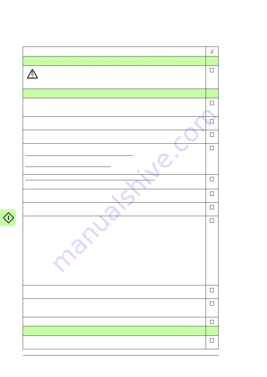
Start-up procedure
Tasks
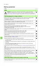
Safety
WARNING!
Follow the safety instructions during the start-up procedure. See
Safety
instructions for ACS880 multidrive cabinets and modules
(3AUA0000102301 [English]) and
on page
42.
Only qualified electricians are allowed to start-up
the drive.
Checks/Settings with no voltage connected
Make sure that it is safe to start the work. Obey the drive work instructions for switching off and
disconnecting in
Safety instructions for ACS880 multidrive cabinets and modules
(3AUA0000102301 [English]).
Make sure that the disconnector of the supply transformer is locked to the off (0) position, that
means no voltage is, or cannot be connected to drive inadvertently.
Make sure that all external auxiliary circuits are switched off and disconnected. See the circuit
diagrams delivered with the drive.
Make sure that the drive main disconnecting device is open and locked:
Drives with a main switch/disconnector ([Q1], F253): Open and lock the main
switch/disconnector of the drive.
Drives with a main breaker ([Q1], F255): Crank the main breaker to the DISCONNECTED
position.
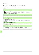
DC/DC converter with the DC switch/disconnector ([Q11], F286):
Make sure that the DC switch/disconnector [Q11] is open and locked.
Make sure that the energy storage disconnector is open and locked to open position (customer-
installed device).
Make sure that the mechanical and electrical installation of the converter unit
has been inspected
and is OK. See chapter
.
Make sure that the drive is ready for the converter unit start-up:
• The supply and inverter units have been installed according to the instructions given in their
hardware manuals.
• The supply unit has been started up according to the instructions given in the appropriate supply
unit manual.
• The inverter units have been started up according to the instructions given in the hardware
manual and appropriate firmware manual.
For the supply and inverter unit hardware manuals, see
the inside of the front
cover.
Note:
If the drive has been stored over one year: Reform the electrolytic DC capacitors in the DC
bus of the drive. See the separate reforming instructions (available in the Internet or from your local
ABB representative).
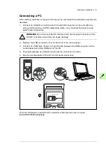
Make sure that the DC/DC converter is equipped with a control panel (J400), or preferably,
you have a PC with the Drive composer tool connected to the converter control unit [A41].
Close the auxiliary voltage circuit breakers of the converter unit [F21.1, F26.1]. Close also other
circuit breakers in between the converter control unit [A41] and the auxiliary voltage switch [Q21] of
the drive supply unit. See the circuit diagrams delivered with the drive.
Close all cabinet doors.
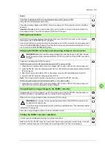
Connecting voltage to the drive and converter control unit
Connect the main AC voltage to the input terminals of the drive supply unit. (Close the main breaker
of the supply transformer.)
Содержание ACS880-1607
Страница 1: ...ABB industrial drives Hardware manual ACS880 1607 DC DC converter units ...
Страница 4: ......
Страница 12: ...12 Introduction to the manual ...
Страница 34: ...34 Mechanical installation ...
Страница 40: ...40 Guidelines for planning electrical installation ...
Страница 52: ...52 Electrical installation ...
Страница 68: ...68 Start up ...
Страница 80: ...80 Maintenance 7 3 4 5 6 ...
Страница 82: ...82 Maintenance 3 4 5 6 7 8 9 9 ...
Страница 85: ...Maintenance 85 12 Install and tighten the two screws 10 11 12 ...
Страница 92: ...92 Maintenance 3 6 4 5 4 7a 7b 7b ...
Страница 93: ...Maintenance 93 9 8 8 10 11 ...
Страница 96: ...96 Maintenance 4 8 6 7 5 3 ...
Страница 97: ...Maintenance 97 9 ...
Страница 118: ...118 Dimensions Dimension drawings Frame 1 R8i bottom cable entry ...
Страница 119: ...Dimensions 119 Frame 1 R8i top cable entry ...
Страница 120: ...120 Dimensions Location and size of input terminals Frame 1 R8i bottom cable entry Frame 1 R8i top cable entry ...
Страница 122: ...www abb com drives www abb com drivespartners 3AXD50000023644 Rev B EN 2017 01 30 Contact us ...

