Operation principle and hardware description 19
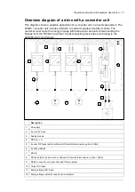
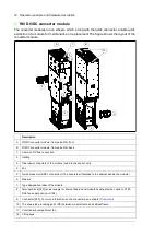
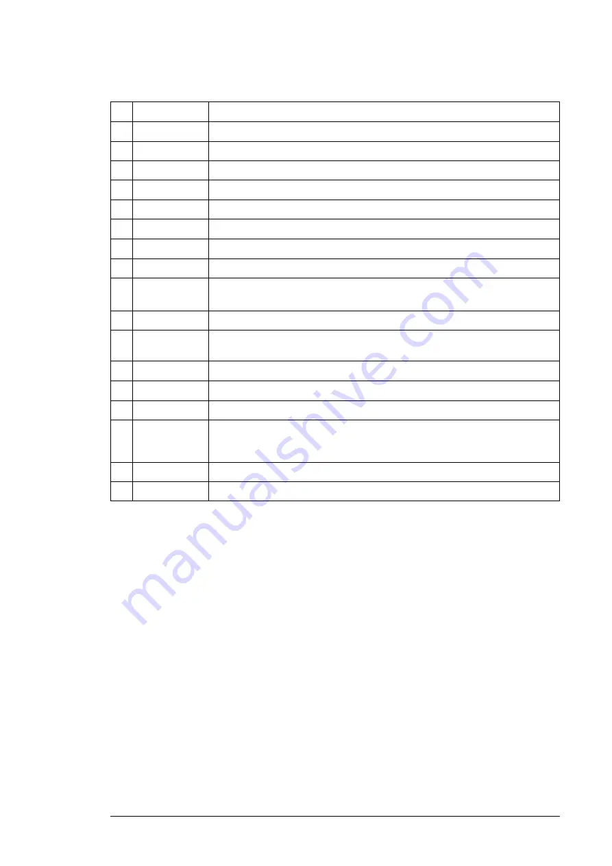
Designation
Description
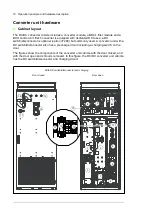
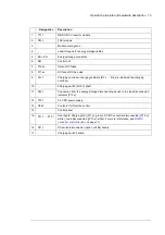
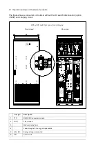
1.
T11.1
R8i DC/DC converter module
2. R13.1
Filter
module
3.
-
Module cooling fans
4.
-
Lead-throughs for energy storage cables
5.
ES+, ES-
Energy storage connection
6. A41
Control
unit
7. F13.xx
Output
DC
fuses
8.
F11.xx
DC fuses (DC bus side
9. A11.1
Charging controller; charging resistors [R1.x
…
R4.x) are behind the charging
controller
10. -
Charging switch [Q10.1] shaft
11. X33.1
Connection from the energy storage disconnecting device to the load disconnected
indicator [P13.x]
12. T22.1
24 V DC power supply
13. Q26.1
Contactor for filter fan control
14. Control
panel
15. P11.1
…
P13.1
Door lights: Charging OK ([P11.x], green), DC/DC converter disconnected ([P12.x],
white), Load disconnected ([P13.x], white). For more information, see
16. Q11.1
DC switch/disconnector (F286) handle
17. -
Charging
switch
handle.
Содержание ACS880-1607
Страница 1: ...ABB industrial drives Hardware manual ACS880 1607 DC DC converter units ...
Страница 4: ......
Страница 12: ...12 Introduction to the manual ...
Страница 34: ...34 Mechanical installation ...
Страница 40: ...40 Guidelines for planning electrical installation ...
Страница 52: ...52 Electrical installation ...
Страница 68: ...68 Start up ...
Страница 80: ...80 Maintenance 7 3 4 5 6 ...
Страница 82: ...82 Maintenance 3 4 5 6 7 8 9 9 ...
Страница 85: ...Maintenance 85 12 Install and tighten the two screws 10 11 12 ...
Страница 92: ...92 Maintenance 3 6 4 5 4 7a 7b 7b ...
Страница 93: ...Maintenance 93 9 8 8 10 11 ...
Страница 96: ...96 Maintenance 4 8 6 7 5 3 ...
Страница 97: ...Maintenance 97 9 ...
Страница 118: ...118 Dimensions Dimension drawings Frame 1 R8i bottom cable entry ...
Страница 119: ...Dimensions 119 Frame 1 R8i top cable entry ...
Страница 120: ...120 Dimensions Location and size of input terminals Frame 1 R8i bottom cable entry Frame 1 R8i top cable entry ...
Страница 122: ...www abb com drives www abb com drivespartners 3AXD50000023644 Rev B EN 2017 01 30 Contact us ...

