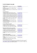


16 Operation principle and hardware description
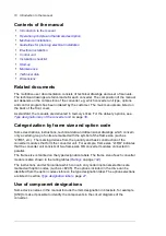
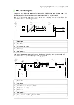
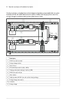
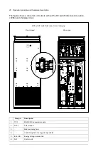
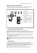
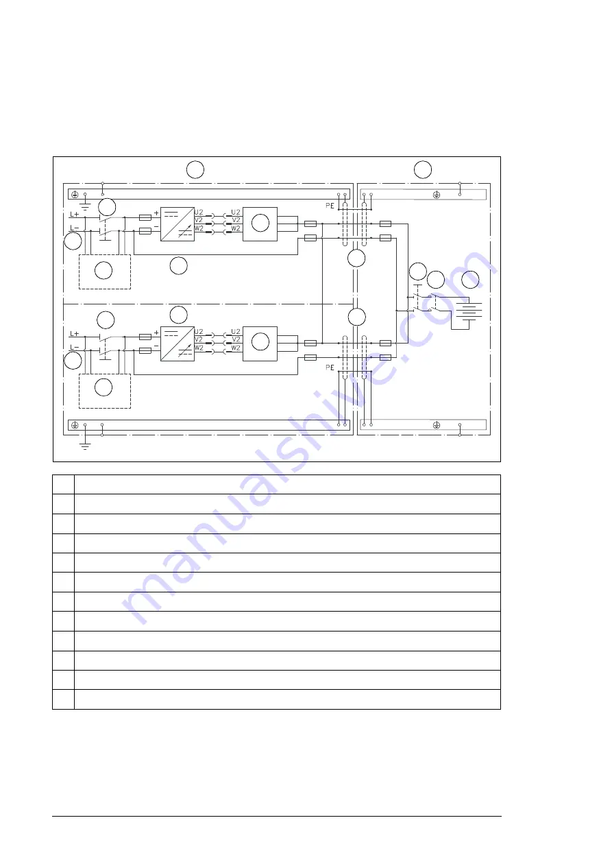
This figure shows a simplified main circuit diagram of parallel-connected DC/DC converter
modules with the DC switch/disconnector (F286) and charging circuit. Also the
energy storage and related cabling and equipment are visible.
Description
1. DC/DC
converter
cubicles
2. Energy
storage
cabinet
3.
Drive DC bus
4.
DC switch/disconnector (F286)
5.
Charging components (belong to F286)
6. DC/DC
converter
module
7. Filter
module
8.
Cabling between DC/DC converter unit and energy storage
9. Energy
storage
disconnector
10. Contactor
11. Energy
storage.
(6
(6
(6
(6
(6
(6
(6
(6
(6
(6
1
2
3
3
4
4
9
10
11
6
6
7
7
5
5
8
8
Содержание ACS880-1607
Страница 1: ...ABB industrial drives Hardware manual ACS880 1607 DC DC converter units ...
Страница 4: ......
Страница 12: ...12 Introduction to the manual ...
Страница 34: ...34 Mechanical installation ...
Страница 40: ...40 Guidelines for planning electrical installation ...
Страница 52: ...52 Electrical installation ...
Страница 68: ...68 Start up ...
Страница 80: ...80 Maintenance 7 3 4 5 6 ...
Страница 82: ...82 Maintenance 3 4 5 6 7 8 9 9 ...
Страница 85: ...Maintenance 85 12 Install and tighten the two screws 10 11 12 ...
Страница 92: ...92 Maintenance 3 6 4 5 4 7a 7b 7b ...
Страница 93: ...Maintenance 93 9 8 8 10 11 ...
Страница 96: ...96 Maintenance 4 8 6 7 5 3 ...
Страница 97: ...Maintenance 97 9 ...
Страница 118: ...118 Dimensions Dimension drawings Frame 1 R8i bottom cable entry ...
Страница 119: ...Dimensions 119 Frame 1 R8i top cable entry ...
Страница 120: ...120 Dimensions Location and size of input terminals Frame 1 R8i bottom cable entry Frame 1 R8i top cable entry ...
Страница 122: ...www abb com drives www abb com drivespartners 3AXD50000023644 Rev B EN 2017 01 30 Contact us ...


