Expansion Stages and System Capacity
40
Aastra 415/430 as of R3.2
syd-0344/1.6 – R3.2 – 09.2014
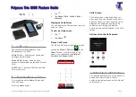
The diagram below shows the position of all the interfaces and slots on the main-
board display and control elements and on the front panel.
Legend:
IIC1...4
Slots for interface cards (trunk cards, terminal cards and options cards)
WA1...4
slots for wiring adapters
SM1
Slot for stackable system modules, type 1 (DSP(X) modules)
SM2
Slot for stackable system modules, type 2 (not used for the moment)
Fig. 7
Mainboard interfaces, display and control elements and front panel
Mainboard
(A430)
(A430)
(A430)
(A430)
(A430)
(A430)
(A430)
SM1
SM2
DSI
FXS
WA1
WA3
WA2
WA4
IC4
IC3
IC2
IC1
EIM
FAN
Ethernet
WA0
Front
panel
Audio
input
Socket for
plug-in
power
supply unit
Pilot key
LED display
Internal interfaces
Connector
for fan
Cardholder for
EIM card