12
7. SETUP
Verify that power of both the AD-8121B and the instrument are turned off before
connecting them together.
1. Connecting to the instrument
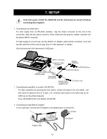
For data supply from an RS-232C interface, plug the 25-pin connector at the end of the
connection cable into the output connector of the instrument and plug the smaller connector into
the printer INPUT connector.
For data supply by current loop, use the AD8121-01 adapter cable and the connection cable. Set
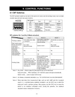
the DIP switch No.4 ON (current loop). See "9-1 DIP Switches" for details.
(Set the baud rate of the instrument to 2400 bps.)
2. Connecting the specified foot switch (AX-SW128)
For data acquisition by pressing the foot switch, connect the plug to the foot switch, and
then insert the plug into the EXT P. jack. The foot switch will function in the same way as the
DATA key on the printer keyboard.
(Plug: AX-KO980-S100, Foot Switch: AX-SW128)
3. Connecting the specified AC Adapter
For AC operation, connect the AC Adapter to the adapter jack on the printer.
Содержание AD-8121B
Страница 1: ...AD 8121B Compact Printer INSTRUCTION MANUAL 1WMPD4000758A...
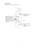
Страница 28: ...26 Printing Example The below is a printing example in the chart printing mode...
Страница 34: ...32 MEMO...


