background image

440

C

HAPTER

 13: C

ONFIGURING


AND

 M

ANAGING

 PNNI (F

OR


THE

 E

XTENDED

 V

ERSION

 O

NLY

)

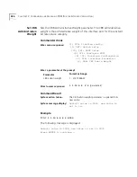
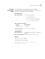
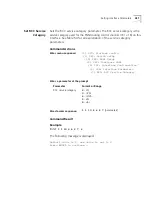
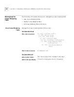
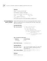
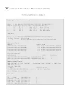
Get Cache State

Display the current DTL cache state. The DTL cache state may be 
ENABLED or DISABLED. The default cache state is ENABLED. 

Command Actions

Command Result

Example

Enter: 

1 1 10 4 6 1 

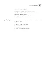
The following message is displayed:

PNNI Cache (for UBR) is ENABLED.

Press ENTER to continue....

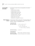
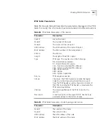
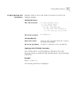
Enter menu sequence:


(1) SYS: Platform config

(1) SET: Switch setup

(10) PNI: PNNI Setup

(4) CFP: Configure PNNI

(6) SCR: Set Route Cache (UBR)

Configuration

(1) GCS: Get Cache State

Direct access sequence:

1 1 10 4 6 1

System action taken:

The current DTL cache state is displayed.

System message display:

PNNI Cache (for UBR) is 

ENABLED/DISABLED.

Press ENTER to continue....

Содержание CoreBuilder 7000

Страница 1: ...http www 3com com CoreBuilder 7000 Family ATM Switches Management Guide Software Version 4 55 Base and Extended Part No DMA3700 0AAA02 Published January 2000 ...

Страница 2: ... and the software described herein are provided to you subject to the following All technical data and computer software are commercial in nature and developed solely at private expense Software is delivered as Commercial Computer Software as defined in DFARS 252 227 7014 June 1995 or as a commercial item as defined in FAR 2 101 a and as such is provided with only such rights as are provided in 3C...

Страница 3: ...ents 24 Year 2000 Compliance 24 1 OVERVIEW CoreBuilder 7000 Family of ATM Switches 25 CoreBuilder 7000 Switch 26 CoreBuilder 7000HD Switch 28 Switch Processors 30 Device Management 31 Interruption free Operation 31 LANE Security 32 Traffic Management 32 ATM Networks 32 Standards and Protocols Supported 34 ATM 34 Protocols 34 Standards 34 2 USING THE LOCAL MANAGEMENT APPLICATION Management Capabili...

Страница 4: ...re and Configuration 47 Download System Software by TFTP 47 Download System Software by Serial Port 48 Upload Configuration Parameters 49 Download Configuration Parameters 51 Display TFTP Download Status 54 Managing the Power Supply 56 Display Power Supply Info 56 Logging Out and Rebooting 57 Logout 57 Reboot 58 Reboot Redundant Switch 59 Fast Setup Procedure 60 Fast Setup 60 Network Prefix 62 Dis...

Страница 5: ... Community String Address 81 Display Ethernet Encapsulation Type 82 Update Ethernet Encapsulation Type 83 Display Single IP Mode 84 Enable Disable Single IP Mode 85 Resetting Configuration Parameters 86 Display Configuration Parameter Groups 86 Reset All Configuration Parameters 87 Reset All Configuration Parameters Except IP Address 90 Reset Configuration Parameter Group 91 Managing Switch Module...

Страница 6: ...ort Interface Type 121 Update Port Interface Type 123 Physical Link Failure Indicator 125 Display Link Failure Indicator Sensitivity 125 Update Link Failure Indicator Sensitivity 126 6 ILMI CONFIGURATION ILMI Setup 127 Display ILMI Version 128 Update ILMI Version 129 Display Auto Configuration Status 130 Enable Disable Auto Configuration 131 Display Auto Discovery Status 132 Enable Disable Auto Di...

Страница 7: ...ses from Flash 163 7 CONFIGURING VIRTUAL CHANNELS Display Call Routing 165 Display Call Routed to ATM Address 165 Display Virtual Channels at Port 173 Display Virtual Channel to IME Address 173 Display Virtual Channel to Static Address 176 Display Virtual Channel to De Registered Address 178 Create Permanent Virtual Channel PVC 179 Display PVC VPI VCI Limits 179 Create UBR PVC Full Setup 180 Creat...

Страница 8: ...er Resolution 212 Save Protocol Timer Resolution 213 Display UNI Signaling Timers 214 Display QSAAL Signaling Timers and SSCOP Configuration 216 Call Admission Control 219 Display CAC Parameters 219 Configuring VP Tunnels 220 Display VP Tunneling Mode 221 Enable VP Tunneling Mode 222 Disable VP Tunneling Mode 223 Display Ports Enabled for VP Tunneling 224 Enable Port for VP Tunneling 225 Disable P...

Страница 9: ...stics 252 9 MANAGING LAN EMULATION SERVICES LAN Emulation Services Setup 253 Display LAN Emulation Services Status 254 Enable LAN Emulation Services 255 Disable LAN Emulation Services 256 Display LECS Status 257 Enable LECS 258 Disable LECS 259 LAN Emulation Redundancy Setup 260 Display LECS Redundancy 260 Add LECS to LECS Order Database 261 Delete LECS from LECS Order Database 262 Display LE Serv...

Страница 10: ...RVICE LECS LECS Address 286 Display Resident LECS Address 286 Update Resident LECS Address 287 LECS Search Policy 288 Display LECS Search Policy 288 LECS ELAN Database Operations 289 Display ELANs 290 Display ELAN Parameters in LECS Database 292 Update ELAN Parameters in LECS Database 293 Display ELAN MAC Addresses 295 Delete ELAN MAC Address 296 Add ELAN MAC Address 297 Display ELAN ATM Addresses...

Страница 11: ... Parameters in LES Database 326 LE_ARP Policy Configuration 328 Display ELAN Response Policy 328 Update ELAN Response Policy 330 Display LE_ARP Response Policy 331 Update LE_ARP Response Policy 333 Display LE_ARP Response Policy for Route Descriptor 334 Update LE_ARP Response Policy for Route Descriptor 336 Reset LES Configurations 337 Display LANE Multicast Forward Delay 338 Update LANE Multicast...

Страница 12: ... a Security Check on a LEC 366 Switch Security 367 Display Switch Security Status 367 Enable Disable Switch Security 368 Save Security Configuration 369 Save Security Configuration 369 Restore Security Configuration 370 13 CONFIGURING AND MANAGING PNNI FOR THE EXTENDED VERSION ONLY Configuring PNNI Nodes 371 Get Number of Nodes 372 Get Enhanced 164 Address Support State 373 Set Save Enhanced E 164...

Страница 13: ...r Delayed ACK Interval 404 Set AvCR Proportional Multiplier 405 Set AvCR Minimum Threshold 406 Set CDV Proportional Multiplier 407 Set CTD Proportional Multiplier 408 Set SVCC Initiation Time 409 Set SVCC Retry Time 410 Set SVCC Calling Integrity Time 411 Set SVCC Called Integrity Time 412 Set All Timers to Their Default Values 413 Setting Optimization Metrics 414 Get Optimization Metrics 414 Set ...

Страница 14: ...aults 438 Configuring the Route Cache 439 Get Cache State 440 Set Cache State 441 Get Cache Refresh for ADD PARTY 442 Set Cache State for ADD PARTY 443 Get Max Number of Routes per Cache 444 Set Max Number of Routes per Cache 445 Showing PNNI Information 446 Display All PTSEs in Database 446 Display PTSE Node Information 451 Display Topology Link Information 453 Display Summary Address Table 455 D...

Страница 15: ...rom 3Com 465 Returning Products for Repair 467 B COREBUILDER 7000 FAMILY ATM SWITCH SPECIFICATIONS C SAFETY INFORMATION Bodily Harm 473 Körperliche Schäden 474 Dommages corporels 474 Equipment Damage 475 Schäden am Gerät 475 Dommage causé à l équipement 475 D MENU INDEX GLOSSARY INDEX 3COM CORPORATION LIMITED WARRANTY ...

Страница 16: ......

Страница 17: ...or network administrator who is responsible for configuring and managing the CoreBuilder 7000 family ATM switch It assumes a working knowledge of local area network LAN operation and a familiarity with communications protocols that are used on interconnected LANs No prior knowledge of 3Com s CoreBuilder networking equipment is necessary to understand this guide If the information in the release no...

Страница 18: ... 7 How to view traffic flow statistics Chapter 8 How to manage LAN emulation services Chapter 9 How to configure the LAN emulation configuration service Chapter 10 How to configure LAN emulation servers and clients Chapter 11 How to configure LEC ELAN admission security Chapter 12 How to configure and manage PNNI for Extended Version Only Chapter 13 Technical support Appendix A System specificatio...

Страница 19: ...tly as shown and then press Return or Enter Commands appear in bold Example To remove the IP address enter the following command SETDefault 0 IP NETaddr 0 0 0 0 The words enter and type When you see the word enter in this guide you must type something and then press Return or Enter Do not press Return or Enter when an instruction simply says type Keyboard key names If you must press two or more ke...

Страница 20: ...p 1 PAS Password setup 1 REA Set Read access Password Enter parameter at prompt Parameter Format or Range New password Up to eight alphanumeric characters New password again Direct access sequence 1 1 1 1 parameters System action The read access password is updated A B C D Table 3 Command Description Sections Key Section Description A Menu sequence The menu options that need to be selected in orde...

Страница 21: ...rk a CoreBuilder 7000 family ATM switch CoreBuilder 7000 Family ATM Switches Operations Guide This guide contains detailed explanations of the theory of operation of the CoreBuilder 7000 family ATM switch Release Notes on separate CD ROM The release notes contain information about the latest software release The complete documentation for the CoreBuilder 7000 family ATM switches is shown in Table ...

Страница 22: ...200 0BAA01 CoreBuilder 7200 Ethernet ATM Interface Card Operation Guide DUA7200 0AAA01 CoreBuilder 7400 Ethernet ATM Interface Card User Guide DUA7400 0AAA01 CoreBuilder 7600 Fast Ethernet Interface Card User Guide DUA7600 0AAA01 8 Port Board ATM Interface Card User Guide DUA3708 0AAA01 622 Mbps ATM Interface Module User Guide DUA3762 1AAA01 DS 3 Interface Module Installation Guide DIA00DS 1AAA01 ...

Страница 23: ...stall and power up your CoreBuilder 7000 family ATM switch Installation and Startup Guide Learn about how you administer and manage the CoreBuilder 7000 family ATM switch Management Guide Learn about ATM and how it is implemented in the CoreBuilder 7000 family ATM switch Operations Guide Learn about LAN Emulation and how it is implemented in the CoreBuilder 7000 family ATM switch Operations Guide ...

Страница 24: ...bout this guide to sdtechpubs_comments 3Com com Please include the following information when commenting Document Title Document Part Number found on back page of each document and in Table 4 Page Number if appropriate Year 2000 Compliance For information on Year 2000 compliance and 3Com products visit the 3Com Year 2000 Web page http www 3com com products yr2000 html ...

Страница 25: ...rprise networks They allow you to scale performance to extremely high levels as your network grows and evolves The CoreBuilder 7000 family ATM switches include the CoreBuilder 7000 ATM switch and the CoreBuilder 7000HD High Density ATM switch Figure 1 shows a typical configuration of the CoreBuilder 7000 family ATM switch which illustrates its modularity and flexibility It contains two CoreBuilder...

Страница 26: ...FAIL ACT Control Status 10BASE T Status Service Status PWR HD M an agement Service Port 1 0Base T RS232 RS232 Control T erminal 7 0 0 0 H D 3 2 x 3 2 S W I TC H 7 8 0 0 Gi g a b i t Et hernet I F card 4 10 00B AS E S X 1 10 00B ASE S X 2 10 00B AS E S X 3 10 00B AS E S X SYS ACT FAIL PWR 1 2 4 3 1 2 4 3 5 6 8 7 RX T X M M RX T X 100 FX RX T X M M RX T X 100 FX RX T X M M RX T X 100 FX RX T X M M R...

Страница 27: ... cut through non blocking self routing architecture that can handle up to 2 56 Gbps of traffic and supports up to 4096 virtual channels per port This high speed architecture makes it possible to support 16 full rate links both Point to Point and Point to Multipoint The switch s 20 48 Gbps passive backplane enables future expansion to faster switch engines high port density interface cards and high...

Страница 28: ...slot chassis allows for a mixture of port types with versatile media options for a wide range of network configurations Table 6 Interfaces to Ethernet and Fast Ethernet Interface Card Interface Module Type 4 Port ATM Interface Card 155 Mbps OC3 fiber single mode and multimode interface modules 155 Mbps OC UTP5 copper interface module 45 Mbps DS 3 module for WAN links 34 Mbps E 3 WAN interface 7200...

Страница 29: ...o 144 switched Ethernet or up to 64 switched Fast Ethernet ports per chassis The 622 Mbps OC 12c interface modules are supported via the 8 Port ATM Interface Card or the 16 Gigabit 1000 Mbps 622 ATM Interface Carrier Card Up to four interface cards of the following types can be supported simultaneously Interface Card ATM Interface Module Type 8 Port ATM Interface Card 155 Mbps OC3 Multi mode Fiber...

Страница 30: ...mes sec 64 byte frames Maximum number of Fast BUS instances per board 12 Switch Processors An on board i960 processor handles all advanced software features including SVC Switched Virtual Connection signaling and SNMP Simple Network Management Protocol management The Transputer is a dedicated chip used for communication with the 4 Port and 8 Port ATM Interface Cards The ALC matrix is used to commu...

Страница 31: ... SNMP capabilities of the switches with a common user interface and sophisticated administrative features that optimize network configuration oversight and troubleshooting For more information on Transcend contact your 3Com representative Chassis Management Single IP The CoreBuilder 7000 family switch has a single IP address which serves both the switch card and any CoreBuilder 7200 7400 7600 7800...

Страница 32: ...to individual LECs or to groups of LECs sharing the same network prefix For more information about LANE security see LANE Security on page 161 in the Operations Guide Traffic Management Automatic congestion management in the CoreBuilder 7000 family ATM switch platform works to prevent cell loss A variety of flow control mechanisms including Broadcast Suppression EFCI and CLP bit setting support he...

Страница 33: ...With the CoreBuilder 7000 family ATM switch you can establish virtual networks across the enterprise using ATM and LAN Emulation Segments in a virtual network can incorporate legacy LANs and ATM devices using LAN Emulation allowing you to organize network users into logical groups regardless of their physical location Using this feature you can set up workgroups composed of members from various de...

Страница 34: ...ed for connection over the user to network and network to network interfaces as well as for address registration signaling Q2931 for Switched Virtual Connection SVC used for dynamically managing calls and PNNI phase 1 implemented for multiple switch networks For more information see Appendix B in the Operations Guide PNNI is available in version 4 5 extended only To order the Extended version of t...

Страница 35: ...o configure your CoreBuilder 7000 family ATM switch you must run the LMA from a terminal via a direct RS 232 connection or via Telnet To augment network management you can use an external application such as 3Com s Transcend Enterprise Manager ATMvLAN Manager LMA functions include Configuring the platform Managing network interfaces Configuring ILMI Configuring virtual channels Viewing statistics ...

Страница 36: ...r each access level Logging In When you boot the system the following login screen appears CoreBuilder 7000 ATM Backbone Switch Access level read write admin admin Password To login to the LMA 1 Enter your access level the default access level is admin 2 Enter your password the default password is admin After you log in the Main Menu is displayed as shown in Figure 2 Table 7 Access Levels Access L...

Страница 37: ...y another lower level command menu submenu and commands that perform a specific administrative task The submenu command is distinguished by the arrow on the right The Main Menu is at the top of the hierarchy Through it you access the submenus for the main topics of management such as Platform config LAN Emulation and Connections Figure 3 shows the Main Menu and some of its successive submenus CB70...

Страница 38: ...ion of the command It specifies the menu sequence you need to enter the parameters to enter and their format the command results and any system messages CP7000 switch module Main Menu 1 SYS Platform config 2 LEM Lan Emulation 3 CON Connections 4 STS Statistics 5 DIA Testing Diagnostics 6 FTR ATM features 7 LOG Logout 8 VER Version 9 FST Fast Setup Main Back in menus CP7000 switch module Platform c...

Страница 39: ...ord Setup Menu is displayed as follows followed by the path and the prompt 1 SYS 1 SET 1 PAS These menu items are all configuration commands none of them have arrows to the right 4 Enter 1 at the Password Setup Menu prompt The prompt for the new read password is displayed as follows Enter the new read password This completes the menu sequence Entering the Command Parameters Now refer to section B ...

Страница 40: ...ection just type 1 1 1 1 at the Main Menu prompt The direct access menu sequence is included in the command description format shown in Figure 1 Entering Multiple Parameters When a command has more than one parameter you can enter them all on the same command line separated by blanks or you can enter some or all of them on separate command lines If you do not enter them all on one line you are rep...

Страница 41: ...m The parameter is saved to flash memory The method and the timing of these tasks depends on the specific LMA command as described in the following sections Activating a New Parameter The system can activate begin to use a new parameter in one of two ways Immediately Only after the next reboot The method used by a specific LMA command is indicated in its command description Table 9 Editing Aids To...

Страница 42: ... The new parameter value is automatically saved to flash when the parameter is entered The new parameter value is saved to flash by a separate save command for that parameter The method used by a specific LMA command is indicated in its command description Note that if a required save command is not executed before the next reboot the new value will be lost ...

Страница 43: ...iguration Managing the Power Supply Logging Out and Rebooting Fast Setup Procedure Network Prefix Switch Redundancy Password Setup The following commands allow you to set up the access passwords to the LMA or to reset all passwords to their factory defaults Three access passwords are provided read access write access and admin access For normal administrative operation use the admin access passwor...

Страница 44: ...assw Enter the new read password again mypassw The password has been changed The read access password is updated Enter the menu sequence 1 SYS Platform config 1 SET Switch setup 1 PAS Password setup 1 REA Set Read access Password Enter a parameter at the prompt Parameter Format or Range New password Up to eight alphanumeric characters New password again Same password Direct access sequence 1 1 1 1...

Страница 45: ...he new write password again mypassw The password has been changed The write access password is updated Enter the menu sequence 1 SYS Platform config 1 SET Switch setup 1 PAS Password setup 2 WRI Set Write access Password Enter a parameter at the prompt Parameter Format or Range New password Up to eight alphanumeric characters New password again Same password as in step 1 Direct access sequence 1 1...

Страница 46: ...Enter the new admin password newpass Enter the new admin password again newpass The password has been changed The admin access password is updated Enter the menu sequence 1 SYS Platform config 1 SET Switch setup 1 PAS Password setup 3 ADM Set Admin access Password Enter a parameter at the prompt Parameter Format or Range Old password Up to eight alphanumeric characters New password Up to eight alp...

Страница 47: ... Display TFTP Download Status Download System Software by TFTP Performs TFTP software download Specify the server IP address and software file names Command Actions Command Result Enter the menu sequence 1 SYS Platform config 3 Load system s w config 2 FTP Perform TFTP s w download Enter a parameter at the prompt Parameter Format or Range See procedure in the CoreBuilder 7000 Upgrade Instructions ...

Страница 48: ...ad system s w config 3 LCL Prepare for RS 232 download Enter a parameter at the prompt Parameter Format or Range Mode 1 for Load Mode 0 for Operational Mode Direct access sequence 1 3 3 parameters System action taken System is ready for RS 232 software download after the next reboot System message display Load process of file type LECS Order List completed successfully Table 10 Load and Operationa...

Страница 49: ...ee Storing and Retrieving Configuration Parameters on page 75 in the Installation Guide Command Actions Command Result Enter the menu sequence 1 SYS Platform config 3 LOA Load system s w config 6 TCU Upload config from flash to TFTP server Enter a parameter at the prompt Parameter Format or Range Select module 1 5 Select data type 1 9 Server IP address IP address Name of file on server file name w...

Страница 50: ...the TFTP server IP address 100 0 0 111 4 Enter the name of file without an extension to be written to the server to contain the uploaded data switch cfg 24_7_cfg The configuration parameters are uploaded to seven different files with sequential file extensions switch cfg 24_7_cfg 1 to switch cfg 24_7_cfg 7 5 The success status of the upload is displayed as follows Module Types 1 Switch module 7000...

Страница 51: ...more information Storing and Retrieving Configuration Parameters on page 75 in the Installation Guide When the configuration files are downloaded to flash memory they overwrite the previous information The new parameters are not activated immediately but only at the next reboot after they are read from the flash memory Subsequent to a configuration download all LMA set operations are blocked until...

Страница 52: ...oad system s w config 7 TCD Download config from TFTP server to flash Enter a parameter at the prompt Parameter Format or Range Select module 1 5 Select data type 1 9 Server IP address IP address Name of file on server file name with path Continue prompt y or n Direct access sequence 1 3 7 parameters System action taken The selected data of the selected module is downloaded by TFTP from the server...

Страница 53: ...rver that contains the data to be downloaded switch cfg 24_7_cfg The configuration parameters are downloaded from seven different files with sequential file extensions switch cfg 24_7_cfg 1 to switch cfg 24_7_cfg 7 5 The success status of the downloaded files is displayed as follows Load process of file type X completed successfully File Types 1 All 2 Box Profile 3 ATM Addresses 4 PNNI Configurati...

Страница 54: ...taken Last TFTP download status is displayed System message display See Table 11 Table 11 Download Messages Message Meaning and Action System is loading from ip address file Received n System is loading Completed successfully Download has completed Unknown No activity nothing downloaded Error while downloading CRC error download again If the error persists contact 3Com technical support No respons...

Страница 55: ...lows Download process status is Unknown System Loader cannot reach the server Check the following cable connection if TFTP server is up TFTP server IP address Flash memory partially erased After downloading switch software Download software again via RS 232 port Table 11 Download Messages continued Message Meaning and Action ...

Страница 56: ... Power Supply on page 85 in the Installation Guide for more information about redundant power supplies Command Actions Command Result Table 12 presents the possible status of the power supplies Example Enter 1 6 Information about the power supplies in the CoreBuilder 7000 family ATM switch chassis is displayed Enter the menu sequence 1 SYS Platform config 6 PWS Power supplies Direct access sequenc...

Страница 57: ...log you out of the system Command Actions Command Result Example Enter 7 The system logs out and the login screen is displayed as shown below CoreBuilder 7000 ATM Backbone Switch Access level read write admin Enter the menu sequence 7 LOG Logout Enter a parameter at the prompt Parameter Format or Range Confirm logout y or n Direct access sequence 7 System action taken Logs out the system System me...

Страница 58: ... reboot the login screen is displayed If you have configured one or more of the switch parameters either through a LMA menu item or through the Fast Setup and a redundant switch is present wait three minutes before rebooting to allow the redundant switch to be updated Enter the menu sequence 1 SYS Platform config 7 RBO Reboot Enter a parameter at the prompt Parameter Format or Range Confirm reboot...

Страница 59: ... want to reboot the redundant switch y n Enter y to confirm n to cancel Enter the menu sequence 1 SYS Platform config 8 RBR Reboot redundant switch Enter a parameter at the prompt Parameter Format or Range Confirm reboot y or n Direct access sequence 1 8 System action taken Reboots the redundant switch System message display Do you really want to reboot the redundant switch y n ...

Страница 60: ...rs on the CoreBuilder 7000 family ATM switch See Integrated Fast Setup on page 56 in the Installation Guide for a detailed description of the fast setup procedure Command Actions Command Result Enter the menu sequence 9 FST Fast Setup Direct access sequence 9 System action taken Performs a fast setup of the switch System message display The fast setup opening screen is displayed as shown in the ex...

Страница 61: ...ration will be overridden Fast Setup Utility The flash configuration will be displayed below Update if needed and then hit Enter To move between sections enter the following characters at end of line Back and forth in sections S Jump to section ID S Back to beginning of setup To end of setup Only in Virtual Network Configuration section group slot item port G Jump to group G I Jump to item I Updat...

Страница 62: ...lder 7000 family ATM switch Command Actions Command Result Example Enter 1 1 6 1 The following information is displayed Current Switch Network Prefix 47 0 0 0 0 0 3c 0 0 a0 0 0 0 Significant Length Prefix is 19 Enter the menu sequence 1 SYS Platform config 1 SET Switch setup 6 SNP Switch Network Pref setup 1 GET Get Network Prefix Direct access sequence 1 1 6 1 System action taken The network pref...

Страница 63: ...First byte 47 39 Enter a Network prefix Enter the menu sequence 1 SYS Platform config 1 SET Switch setup 6 SNP Switch Network Pref setup 2 SET Set save Network Prefix Enter a parameter at the prompt Parameter Format or Range Network Prefix 13 bytes First byte 47 39 Direct access sequence 1 1 6 2 parameters System action taken The network prefix is updated in flash memory The change takes place aft...

Страница 64: ...and Actions Command Result Example Enter 1 1 13 1 The following information is displayed Enter the menu sequence 1 SYS Platform config 1 SET Switch setup 13 SRS Switch Redundancy setup 1 STA Display switch red status Direct access sequence 1 1 13 1 System action taken The switch redundancy status of the CoreBuilder 7000 family ATM switch is displayed System message display Information is displayed...

Страница 65: ...suspended Switch Engine Slot 2 I F card for communication Slot number of interface card to be used for communication Inter Switch Communication status Established or not established Configuration status Synchronized or not synchronized Enter the menu sequence 1 SYS Platform config 1 SET Switch setup 13 SRS Switch Redundancy setup 2 SRM Set switch redundancy mode Enter a parameter at the prompt Par...

Страница 66: ...ns Guide Set Redundant Switch Mode Sets the redundant switch mode Command Actions Command Result Example Enter 1 1 13 3 The following prompt is displayed Enter parameter s 0 Standby 1 Suspended Enter 0 to specify standby mode for the redundant switch Enter the menu sequence 1 SYS Platform config 1 SET Switch setup 13 SRS Switch Redundancy setup 3 SSM Set redundant switch mode Enter a parameter at ...

Страница 67: ...communication The following information is displayed Enter the menu sequence 1 SYS Platform config 1 SET Switch setup 13 SRS Switch Redundancy setup 4 SIR Force I F for red comm Enter a parameter at the prompt Parameter Range Slot id 3 6 Direct access sequence 1 1 13 4 System action taken The interface card in the specified slot becomes the card used for redundancy communication System message dis...

Страница 68: ...68 CHAPTER 3 GENERAL TASKS ...

Страница 69: ...are Versions EFCI Threshold Setting Up for PNNI Setting Up for Management The following commands allow you to set up the parameters for managing the CoreBuilder 7000 family ATM switch Display Current IP Configuration Update IP Address Display Current NMS Configuration Update NMS Address Display Current Default Gateway Configuration Update Default Gateway Address Display Current Subnet Mask Configu...

Страница 70: ... Displays the current IP address of the CoreBuilder 7000 family ATM switch Command Actions Command Result Example Enter 1 1 2 1 1 The following message is displayed Current IP address 151 104 78 86 Enter the menu sequence 1 SYS Platform config 1 SET Switch setup 2 MNG Management setup 1 SIP IP Setup 1 GIP Get IP Address Direct access sequence 1 1 2 1 1 System action taken The current IP address is...

Страница 71: ...The IP address is updated to 100 0 2 2 after the next reboot It is essential to change the factory default IP address to match your network addresses Enter the menu sequence 1 SYS Platform config 1 SET Switch setup 2 MNG Management setup 1 SIP IP Setup 2 SIP Set Save IP Address Enter a parameter at the prompt Parameter Format or Range IP Address valid IP address Direct access sequence 1 1 2 1 2 pa...

Страница 72: ...he NMS address Command Actions Command Result Example Enter 1 1 2 2 1 The following message is displayed Current NMS address 151 104 78 75 Enter the menu sequence 1 SYS Platform config 1 SET Switch setup 2 MNG Management setup 2 NMS NMS Setup 1 GNS Get NMS Address Direct access sequence 1 1 2 2 1 System action taken Current NMS configuration is displayed System message display Current NMS address ...

Страница 73: ...xample Enter 1 1 2 2 2 100 1 0 131 The NMS address is updated to 100 1 0 131 Enter the menu sequence 1 SYS Platform config 1 SET Switch setup 2 MNG Management setup 2 NMS NMS Setup 2 SNS Set Save NMS Address Enter a parameter at the prompt Parameter Format or Range NMS address valid IP address Direct access sequence 1 1 2 2 2 parameters System action taken The NMS address is updated after the next...

Страница 74: ... on the local subnet Command Actions Command Result Example Enter 1 1 2 3 1 The following message is displayed Current Default Gateway address 151 104 78 20 Enter the menu sequence 1 SYS Platform config 1 SET Switch setup 2 MNG Management setup 3 GWY Default gateway setup 1 GGW Get default gateway Direct access sequence 1 1 2 3 1 System action taken The current default gateway configuration is dis...

Страница 75: ... 2 100 1 0 254 The Default Gateway address is updated to 100 1 0 254 Enter the menu sequence 1 SYS Platform config 1 SET Switch setup 2 MNG Management setup 3 GWY Default Gateway Setup 2 SGW Set Save Default Gateway Enter a parameter at the prompt Parameter Format or Range Default gateway address valid IP address Direct access sequence 1 1 2 3 2 parameters System action taken The default gateway a...

Страница 76: ...he IP address Command Actions Command Result Example Enter 1 1 2 4 1 The following message is displayed Current Subnet Mask address 255 255 255 0 Enter the menu sequence 1 SYS Platform config 1 SET Switch setup 2 MNG Management setup 4 MSK Subnet Mask Setup 1 GSM Get Subnet Mask Direct access sequence 1 1 2 4 1 System action taken The current subnet mask configuration is displayed System message d...

Страница 77: ...Result Example Enter 1 1 2 4 2 255 255 255 0 The Subnet Mask address is updated to 255 255 255 0 Enter the menu sequence 1 SYS Platform config 1 SET Switch setup 2 MNG Management setup 4 MSK Subnet Mask Setup 2 SSM Set Save Subnet Mask Enter a parameter at the prompt Parameter Format or Range Subnet mask address valid IP address Direct access sequence 1 1 2 4 2 parameters System action taken The s...

Страница 78: ...ns Command Result Example Enter 1 1 2 5 1 The following message is displayed Current Read Community String public Enter the menu sequence 1 SYS Platform config 1 SET Switch setup 2 MNG Management setup 5 GET Get Comm String Setup 1 GET Get Get Comm String Direct access sequence 1 1 2 5 1 System action taken The current read community string configuration is displayed System message display Current...

Страница 79: ...to public Enter the menu sequence 1 SYS Platform config 1 SET Switch setup 2 MNG Management setup 5 GET Get Comm String Setup 2 SET Set save Get Comm String Enter a parameter at the prompt Parameter Format or Range Read community string alphanumeric string up to 19 characters normally set to public or private Direct access sequence 1 1 2 5 2 parameters System action taken The read community string...

Страница 80: ...s Command Result Example Enter 1 1 2 6 1 The following message is displayed Current Write Community String private Enter the menu sequence 1 SYS Platform config 1 SET Switch setup 2 MNG Management setup 6 SET Set Comm String Setup 1 GET Get Set Comm String Direct access sequence 1 1 2 6 1 System action taken The current write community string configuration is displayed System message display Curre...

Страница 81: ... to private Enter the menu sequence 1 SYS Platform config 1 SET Switch setup 2 MNG Management setup 6 SET Set Comm String Setup 2 SET Set save Set Comm String Enter a parameter at the prompt Parameter Format or Range Write Community String alphanumeric string up to 19 characters normally set to public or private Direct access sequence 1 1 2 6 2 parameters System action taken The Write Community St...

Страница 82: ...that enter through the Ethernet management port For more information see Ethernet Encapsulation Type on page 204 in the Operations Guide Command Actions Command Result Example Enter 1 1 2 7 1 The following message is displayed Current Eth Type is ETH Enter the menu sequence 1 SYS Platform config 1 SET Switch setup 2 MNG Management setup 7 ETH Eth Type Setup 1 GET Get Eth Type Direct access sequenc...

Страница 83: ...ions Guide Command Actions Command Result Example Enter 1 1 2 7 2 1 The following message is displayed Eth Type was successfully set for the next reboot Enter the menu sequence 1 SYS Platform config 1 SET Switch setup 2 MNG Management setup 7 ETH Eth Type Setup 2 SET Set save Eth Type Enter a parameter at the prompt Parameter Format or Range Ethernet encapsulation type 1 for type ETH 0 for type LL...

Страница 84: ...ent Single IP on page 197 in the Operations Guide Command Actions Command Result Example Enter 1 1 2 8 1 The following message is displayed The current Mode is single IP mode Enter the menu sequence 1 SYS Platform config 1 SET Switch setup 2 MNG Management setup 8 SIS Single IP setup 1 GSI Get Single IP Mode Direct access sequence 1 1 2 8 1 System action taken The single IP mode is displayed Syste...

Страница 85: ...mand Actions Command Result Example Enter 1 1 2 8 2 2 The following mesage is displayed Single IP mode has changed to Multiple IP mode Multiple IP mode is enabled Enter the menu sequence 1 SYS Platform config 1 SET Switch setup 2 MNG Management setup 8 SIS Single IP setup 2 SSI Set save Single IP Mode Enter a parameter at the prompt Parameter Format or Range Single IP select 1 to enable single IP ...

Страница 86: ...rganized in flash memory Command Actions Command Result Example Enter 1 2 1 The following information is displayed Enter the menu sequence 1 SYS Platform config 2 FLS Flash setup 1 DCG Display config param groups Direct access sequence 1 2 1 System action taken All configuration parameter groups are displayed System message display Information is displayed as shown in the example below Block ID Gr...

Страница 87: ...rameters Table 14 Configuration Parameter Groups Parameter Description Block ID The id of the flash block in which the region is located Group name Flash regions Group ID ID for the region Maximum length Maximum length in bytes Actual length Actual length in bytes No of rec Number of records Table 15 Configuration Parameter Default Values Parameter Set to General Signaling Version UNI 4 0 Signalin...

Страница 88: ...all the ELANs YY 1 2 3 16 and have a local LES instance YY as their LES default ELAN has a local LES instance 0 as its LES admin ELAN has a local LES instance 0 as its LES Resident LECS address Prefix according to the switch prefix Suffix 00 a0 3e 00 00 01 00 Active LECS List Number of entries 0 Platform Network Prefix NULL 00 00 00 00 00 00 00 00 00 00 00 00 00 Link Failure Sensitivity High 5 sec...

Страница 89: ...Y N N Enter Y to confirm N to cancel reset The following message appears All configuration parameters are reset to their factory values Enter the menu sequence 1 SYS Platform config 2 FLS Flash setup 2 RAC Reset all configs to defaults Enter a parameter at the prompt Parameter Format or Range Continue prompt y or n Direct access sequence 1 2 2 System action taken All configuration parameters are r...

Страница 90: ...tch is automatically rebooted The switch is configured after rebooting Command Actions Command Result Example Enter 1 2 3 The following prompt is displayed This will reset all configuration to factory defaults except IP configuration Then the switch will reboot Are you sure Y N Y Enter Y to confirm N to cancel reset Enter the menu sequence 1 SYS Platform config 2 FLS Flash setup 3 REI Reset all co...

Страница 91: ...eters are divided into group according to their location in flash memory You can reset all the parameters in a specific group The following groups can be reset It is recommended to perform this command when the switch is off line After executing this command the switch is automatically rebooted The switch is configured after rebooting Number Configuration Group 1 LECS Database 2 LECS Order List 3 ...

Страница 92: ...ig 2 FLS Flash setup 4 RSG Reset configuration group Enter a parameter at the prompt Parameter Format or Range Group number 1 7 Direct access sequence 1 2 4 System action taken All configuration parameters are reset to their factory default values System message display Reset of parameter group was performed successfully Group Num Group name Max len Actual len No of rec 1 Box Profile 10152 01740 0...

Страница 93: ...he switch modules present 1 2 or both and detailed manufacturing information about the attached module If two switch modules are present in the same chassis one is used for redundancy For more information about redundant switch cards see Chapter 10 in the Operations Guide Command Actions Command Result Example This example is for a CoreBuilder 7000HD switch Enter 1 4 Switch module information is d...

Страница 94: ... Active switch MAC address 00 c0 da 60 1b 9f Redundant switch MAC address 00 c0 da 60 1c 21 Active switch sys up time 3 day s 00 34 48 Press ENTER to continue or x ENTER to exit Active switch technical data Mac addr base 00c0da60 Mac addr index 1b9f Switch name ATM_Switch_X_33_ HD _REV _E Assembly No 503A0015 Assembly rev 1 0 Serial No 767 ALC type MB86687A SRE type SRE L CPU type i960_CF_33 CPU s...

Страница 95: ...e switch type 16 x 16 supports up to a total of 16 155Mbps ATM ports for CoreBuilder 7000 Switch 32 x 32 supports up to a total of 32 155Mbps ATM ports for CoreBuilder 7000HD Switch Switch Mode Can be Active on line Redundant Non relevant Memory Size Specifies the memory capacity of the switch 8M 16M HD 32M HD Clock Speed Specifies matrix clock speed of switch 20 MHz for CoreBuilder 7000 7000HD Sw...

Страница 96: ...mily ATM switch Command Actions Command Result Example Enter 6 The following information is displayed Enter the menu sequence 6 FTR ATM features Direct access sequence 6 System action taken Displays ATM features System message display Information is displayed as shown in the example SVC signaling compliant with UNI 3 0 3 1 PVC support via management P2P support P2M support ILMI address registratio...

Страница 97: ...ence 8 VER Version Direct access sequence 8 System action taken The software versions are displayed System message display Information is displayed as shown in the example CoreBuilder Software Versions Active Switch version 4 5 Extended Base Internal Communication version 3 50O I F Control Card 1 version Ver 3 50P I F Control Card 2 version Ver 3 40 4 PB FPGA Transmit version 1 0 4 PB FPGA Receive...

Страница 98: ... switch the EFCI threshold mode is not configurable and is always set to 50 Display EFCI Threshold Displays the EFCI Threshold of the CoreBuilder 7000 switch Command Actions Command Result Example Enter 1 1 7 1 The following message is displayed EFCI threshold mode is 50 full Enter the menu sequence 1 SYS Platform config 1 SET Switch setup 7 FCI EFCI threshold setup 1 GET Get EFCI threshold Direct...

Страница 99: ... 2 The following message is displayed The EFCI threshold is updated to 50 Enter the menu sequence 1 SYS Platform config 1 SET Switch setup 7 FCI EFCI threshold setup 2 SET Set save EFCI threshold Enter a parameter at the prompt Parameter Format or Range EFCI Threshold 0 Disable Full 1 20 2 50 3 80 Direct access sequence 1 1 7 2 parameters System action taken The EFCI Threshold is updated System me...

Страница 100: ... representitive Display PNNI E IISP State Displays the PNNI E IISP status and the next reboot state The status is either PNNI or E IISP Command Actions Command Result Example Enter 1 1 10 1 The following message is displayed PNNI E IISP State PNNI Next reboot value PNNI Enter menu sequence 1 SYS Platform config 1 SET Switch setup 10 PNI PNNI Setup 1 VPS View PNNI E IISP State Direct access sequenc...

Страница 101: ...ext reboot PNNI E IISP routing mode was set to PNNI for the next reboot The status of the routing mode is set to PNNI for the next reboot Enter menu sequence 1 SYS Platform config 1 SET Switch setup 10 PNI PNNI Setup 2 ENP Enable PNNI disable E IISP Direct access sequence 1 1 10 2 System action taken The PNNI E IISP state of the routing mode is set to PNNI and the value is displayed System message...

Страница 102: ...IISP for the next reboot PNNI E IISP routing mode was set to E IISP for the next reboot The status of the routing mode is set to PNNI for the next reboot Enter menu sequence 1 SYS Platform config 1 SET Switch setup 10 PNI PNNI Setup 3 DIP Enable E IISP disable PNNI Direct access sequence 1 1 10 3 System action taken The PNNI E IISP state of the routing mode is set to E IISP and the value are displ...

Страница 103: ...rd Parameters Enable Interface Disable Interface Port Reinitialize Interface Set and Save Interface Mode Display Interface Card Ignore Slot Status Ignore Interface Card Slot Display OC 3 Interface Module Info Display 622 Interface Module Information Display Clock Synchronization Mode Set and Save Clock Synchronization Mode Port Interface Type Physical Link Failure Indicator For a description of th...

Страница 104: ...llows Enter the menu sequence 1 SYS Platform config 5 IFC Interface cards Direct access sequence 1 5 System action taken Interface Module slot occupancy information is displayed System message display See Table 17 and the example below Table 17 Interface Card Slot Occupancy Parameters Parameter Description Slot ID Slot numbers Slot status Slot occupancy Occupied Interface card installed in slot Fr...

Страница 105: ...thernet ATM module Up 4 Occupied 7600 Fast Ethernet module Up 5 Free Not exist 6 Occupied 8 port ATM I F card Up CB7000 switch module Interface cards Menu 1 IF1 Interface card 1 2 IF2 Interface card 2 3 IF3 Interface card 3 4 IF4 Interface card 4 Main Back in menus 0 To switch n To i f card n 1 4 1 SYS 5 IFC 3 ...

Страница 106: ...ters Example Enter 1 5 1 Parameters of the interface modules at the ports of the selected interface Card 1 an 8 Port Board ATM interface card are displayed Enter the menu sequence 1 SYS Platform config 5 IFC Interface cards n IFn n 1 4 Enter a parameter at the prompt Parameter Format or Range Slot ID 3 6 Direct access sequence 1 5 n 1 parameters System action taken Parameters for the interface mod...

Страница 107: ...n 6 8 OC3 SC B Multi mode fiber Up Connect Enabled SONET Intern Table 18 Interface Parameters Parameter Description If ID Interface ID The port ID number for each of the card s ports Physical Type The port interface type for example OC3 SC DS 3 BNC The type determines the interface including the type of connector 622 OC 3 Compatibility Type Indicates compatibility of this OC 3 Module with a 622 Mo...

Страница 108: ...sabled port disabled by management Frame Type The interface mode It can be SDH SONET PDH for DS 3 Clock Mode The port clock mode It can be Internal the transmit Tx line uses an internal clock External the recovered clock from the receive Rx line is used For CoreBuilder 7000HD only Table 18 Interface Parameters continued Parameter Description ...

Страница 109: ... following message is displayed Enable port completed successfully Enter the menu sequence 1 SYS Platform config 5 IFC Interface cards n IFn n 1 4 1 EIF Enable interface Enter a parameter at the prompt Parameter Format or Range Port ID slot port Direct access sequence 1 5 n 1 parameters System action taken The selected port on the interface card is enabled System message display Enable port slot p...

Страница 110: ...isabled The following message is displayed Disable port completed successfully Enter the menu sequence 1 SYS Platform config 5 IFC Interface cards n IFn n 1 4 2 DIF Disable interface Enter a parameter at the prompt Parameter Format or Range Port ID slot port Direct access sequence 1 5 n 2 parameters System action taken The selected port on the interface card is disabled System message display Disa...

Страница 111: ...d successfully Port 2 in slot 3 of the selected interface card is re initialized Enter the menu sequence 1 SYS Platform config 5 IFC Interface cards n IFn n 1 4 3 INI Reinit interface Enter a parameter at the prompt Parameter Format or Range Port ID slot port Direct access sequence 1 5 n 3 parameters System action taken The selected port on the interface card is re initialized System message displ...

Страница 112: ...nterface mode of port 2 in slot 3 of the selected interface is set to SONET and saved Enter the menu sequence 1 SYS Platform config 5 IFC Interface cards n IFn n 1 4 4 SPM Set save interface mode Enter a parameter at the prompt Parameter Format or Range Port ID slot port 0 0 For all Interface Mode 0 for SDH 1 for SONET Direct access sequence 1 5 n 4 parameters System action taken The interface mod...

Страница 113: ...The clock operational mode of port 3 2 of the selected interface a OC 3 SC is set to external and saved Enter the menu sequence 1 SYS Platform config 5 IFC Interface cards n IFn n 1 4 5 STM Set save clock op mode Enter a parameter at the prompt Parameter Format or Range Port ID slot port 0 0 For all Interface Mode 0 for Internal 1 for External Direct access sequence 1 5 n 5 parameters System actio...

Страница 114: ... recognize any interface card installed in a specified slot The ignore slot parameter can take the values Ignore and Normal Command Actions Command Result Example Enter 1 3 4 The following is displayed Enter the menu sequence 1 SYS Platform config 3 LOA Load system software 4 GSI Get ignore slot status Direct access sequence 1 3 4 System action taken Ignore slot status is displayed System message ...

Страница 115: ...ysically removing it perform the command twice first with Ignore and then with Normal Command Actions Command Result Example Enter 1 3 5 3 0 The following message is displayed Status has been changed The ignore slot parameter of slot 3 is set to Ignore Enter the menu sequence 1 SYS Platform config 3 LOA Load system software 5 SSI Set ignore slot status Enter a parameter at the prompt Parameter For...

Страница 116: ... information of the selected interface module in port 3 4 of interface card 1 an 8 Port Board ATM interface card is displayed Enter the menu sequence 1 SYS Platform config 5 IFC Interface cards n IFn n 1 4 6 RSE Read IFC technical data 8 Port only Enter a parameter at the prompt Parameter Format or Range Port ID slot port Direct access sequence 1 5 n 6 parameters System action taken Manufacturing ...

Страница 117: ...embly No 503C0033 1D Assembly Rev 1 Serial No CPU Type T400 RX FIFO 1 2_K_BYTE TX High FIFO 1 2_K_BYTE TX Low 1 FIFO 1 2_K_BYTE TX Low 2 FIFO 32_K_BYTE Flash size 128_K_BYTE Flash vendor AMD Production site TRIAX Production date MON_APRIL_14 _1997 Interface card HW version is 5 ...

Страница 118: ...Manufacturing information of the selected interface module in port 3 4 of the interface card 1 an 622 ATM Interface Module is displayed Enter the menu sequence 1 SYS Platform config 5 IFC Interface cards n IFn n 1 4 7 RPE Read PIGGY technical data 622M Port only Enter a parameter at the prompt Parameter Format or Range Port ID slot port Direct access sequence 1 5 n 7 parameters System action taken...

Страница 119: ...16134 Optic Vendor HP Optic Type SDX1622 Serial Type AMCC_3027Y_ _3028Y Framer Type PMC_SUNI622 Fifo 1 Size 8_K_Byte Fifo 2 Size 32_K_Byte Fifo 3 Size 0 5_K_ByteSOLECTRON Production site SOLECTRON Production date DATE 09 04 1997 TIME 09 20 06 Enter the menu sequence 1 SYS Platform config 1 SET Switch setup 12 SCS Clock synchronization setup 1 DCS Display clock synchronization mode Direct access se...

Страница 120: ...s not possible to synchronize ports unless there is a fiber optic cable in the port Command Actions Command Result Example Clock Synchronization for the 8 Port Board in Slot 3 Enter 1 1 12 2 You are prompted to enter the port id Enter 3 1 This message is displayed Enter the menu sequence 1 SYS Platform config 1 SET Switch setup 12 SCS Clock synchronization setup 2 SCS Set save clock synchronizatio...

Страница 121: ...ng commands allow you to configure the port interface type Display Port Interface Type Update Port Interface Type See Chapter 2 for more information about port interface types Display Port Interface Type Displays the ATM interface type for each port of the CoreBuilder 7000 family ATM switch The interface type is either the User Network Interface UNI or one of the Network Network interfaces E IISP ...

Страница 122: ...the Operations Guide PNNI is available in version 4 5 extended only Command Actions Command Result Example Enter 1 1 3 3 The following information is displayed Enter the menu sequence 1 SYS Platform config 1 SET Switch setup 3 NNI NNI setup 3 GIF NNI get interface type Direct access sequence 1 1 3 3 System action taken The interface type for each port of the CoreBuilder 7000 family ATM switch is d...

Страница 123: ...he auto discovery protocol with the peer ATM device For more information about manual discovery Manual Discovery on page 47 in the Operations Guide Interface type Port id 3 1 3 2 3 3 3 4 3 5 3 6 3 7 3 8 Current val NNI NNI UNI UNI E IISP E IISP UNI UNI Next reb val NNI NNI UNI UNI E IISP UNI UNI UNI Port id 4 1 4 2 4 3 4 4 4 5 4 6 4 7 4 8 Current val UNI UNI UNI PNNI UNI UNI UNI UNI Next reb val U...

Страница 124: ...witch setup 3 NNI NNI setup 4 SIF NNI set save interface type Enter a parameter at the prompt Parameter Format or Range Port ID slot port 0 0 for all ports Port Interface type 0 to set interface type to E IISP 1 to set interface type to UNI 2 to set interface type to IISP 3 to set interface type to PNNI Direct access sequence 1 1 3 4 parameters System action taken The interface type for the specif...

Страница 125: ...lure detection mechanism of the CoreBuilder 7000 family ATM switch For more information Link Failure Detection Sensitivity Control on page 129 in the Operations Guide Command Actions Command Result Example Enter 1 1 11 1 The following message is displayed Current port link down indication status is Enabled Sensitivity Medium Enter the menu sequence 1 SYS Platform config 1 SET Switch setup 11 PLD P...

Страница 126: ... the menu sequence 1 SYS Platform config 1 SET Switch setup 11 PLD Port link down indication 2 SET Set save link down sens Enter a parameter at the prompt Parameter Format or Range Port ID slot port Link failure detection enable disable 0 to disable link failure detection 1 for low sensitivity link failure detection 2 for medium sensitivity link failure detection 3 for high sensitivity link failur...

Страница 127: ...uto Configuration Status Enable Disable Auto Configuration Display Auto Discovery Status Enable Disable Auto Discovery Display LECS Address Access Status Update LECS Address Access Status Display ILMI Channel Polling Status Enable Disable ILMI Channel Polling Display ILMI Channel Polling Interval Update ILMI Channel Polling Interval Display Auto Configuration Results Display Auto Discovery Results...

Страница 128: ...re information ILMI Version on page 49 in the Operations Guide Command Actions Command Result Example Enter 1 1 8 1 1 3 2 The following message is displayed ILMI version is 4 0 Enter the menu sequence 1 SYS Platform config 1 SET Switch setup 8 IME ILMI setup 1 VER ILMI version setup 1 GET Get ILMI version Enter a parameter at the prompt Parameter Format or Range Port ID slot port Direct access seq...

Страница 129: ...er the menu sequence 1 SYS Platform config 1 SET Switch setup 8 IME ILMI setup 1 VER ILMI version setup 2 SET Set save ILMI version Enter a parameter at the prompt Parameter Format or Range Port ID slot port IMLI version 0 to update to version 3 0 1 to update to version 3 1 2 to update to version 4 0 Direct access sequence 1 1 8 1 2 parameters System action taken The ILMI version is updated for th...

Страница 130: ...on page 48 in the Operations Guide Command Actions Command Result Example Enter 1 1 8 2 1 3 2 The following message is displayed Auto configuration is ENABLED Enter the menu sequence 1 SYS Platform config 1 SET Switch setup 8 IME ILMI setup 2 AUC Auto Configuration setup 1 GET Get Auto Config status Enter a parameter at the prompt Parameter Format or Range Port ID slot port Direct access sequence ...

Страница 131: ...uto configuration status of port 3 2 is enabled Enter the menu sequence 1 SYS Platform config 1 SET Switch setup 8 IME ILMI setup 2 AUC Auto Configuration setup 2 SET Set save Auto Config stat Enter a parameter at the prompt Parameter Format or Range Port ID slot port Auto configuration enable disable 0 to disable auto configuration 1 to enable auto configuration Direct access sequence 1 1 8 2 2 p...

Страница 132: ... Discovery on page 43 in the Operations Guide Command Actions Command Result Example Enter 1 1 8 3 1 3 2 The auto discovery status at port 3 2 is displayed as follows Auto discovery is ENABLED Enter the menu sequence 1 SYS Platform config 1 SET Switch setup 8 IME ILMI setup 3 AUC Auto discovery setup 1 GET Get Auto discov status Enter a parameter at the prompt Parameter Format or Range Port ID slo...

Страница 133: ...e auto discovery status of port 3 2 is enabled Enter the menu sequence 1 SYS Platform config 1 SET Switch setup 8 IME ILMI setup 3 AUC Auto discovery setup 2 SET Set save Auto Config stat Enter a parameter at the prompt Parameter Format or Range Port ID slot port Auto discovery enable disable 0 to disable auto discovery 1 to enable auto discovery Direct access sequence 1 1 8 3 2 parameters System ...

Страница 134: ...LECS Address Access on page 148 in the Operations Guide Command Actions Command Result Example Enter 1 1 8 4 1 3 2 The following message is displayed LECS via ILMI is ENABLED Enter the menu sequence 1 SYS Platform config 1 SET Switch setup 8 IME ILMI setup 4 MIB ILMI MIB View setup 1 GET Get LECS via ILMI status Enter a parameter at the prompt Parameter Format or Range Port ID slot port Direct acc...

Страница 135: ...8 4 2 3 2 1 The following message is displayed LECS via ILMI is set to ENABLED The LECS via ILMI status of port 2 in slot 3 is enabled Enter the menu sequence 1 SYS Platform config 1 SET Switch setup 8 IME ILMI setup 4 MIB ILMI MIB View setup 2 SET Set save LECS via ILMI sta Enter a parameter at the prompt Parameter Format or Range Port ID slot port LECS via ILMI enable disable 0 to disable LECS v...

Страница 136: ...in the Operations Guide Command Actions Command Result Example Enter 1 1 8 5 1 3 2 The following message is displayed ILMI polling is ENABLED Enter the menu sequence 1 SYS Platform config 1 SET Switch setup 8 IME ILMI setup 5 POL Polling setup 1 GST Get Polling status Enter a parameter at the prompt Parameter Format or Range Port ID slot port Direct access sequence 1 1 8 5 1 parameters System acti...

Страница 137: ... on page 139 Command Actions Command Result Example Enter 1 1 8 5 2 3 2 1 The following message is displayed ILMI polling is set to ENABLED The polling status of port 2 in slot 3 is enabled and is saved to flash Enter the menu sequence 1 SYS Platform config 1 SET Switch setup 8 IME ILMI setup 5 POL Polling setup 2 SST Set Save Polling status Enter a parameter at the prompt Parameter Format or Rang...

Страница 138: ...sult Example Enter 1 1 8 5 3 3 2 The following message is displayed ILMI polling timeout is 30 sec Enter the menu sequence 1 SYS Platform config 1 SET Switch setup 8 IME ILMI setup 5 POL Polling setup 3 GTO Get polling timeout Enter a parameter at the prompt Parameter Format or Range Port ID slot port Direct access sequence 1 1 8 5 3 parameters System action taken The ILMI channel polling interval...

Страница 139: ...ge is displayed ILMI polling timeout reconfigured The polling interval of port 2 in slot 3 is set to 30 seconds and is saved to flash Enter the menu sequence 1 SYS Platform config 1 SET Switch setup 8 IME ILMI setup 5 POL Polling setup 4 STO Set Save Polling timeout Enter a parameter at the prompt Parameter Format or Range Port ID slot port Polling interval Range 5 1800 seconds Direct access seque...

Страница 140: ...y the command Enter the menu sequence 1 SYS Platform config 1 SET Switch setup 8 IME ILMI setup 6 ACV Auto Config Auto Dis View 1 CFG View Auto Config result Enter a parameter at the prompt Parameter Format or Range Port ID slot port Direct access sequence 1 1 8 6 1 parameters System action taken The auto configuration results for the specified port are displayed System message display Information...

Страница 141: ... only Display of Peer Switch Enter 1 1 8 6 1 4 3 The auto configuration results at port 4 3 of the peer switch are displayed as follows It shows that the peer switch is configured to PNNIV1 0 local value and the local switch remote value is configured to EIISP The result of the auto configuration is that the peer switch is reconfigured to EIISP Auto Configuration is active on this port Parameter N...

Страница 142: ... 1 Display Auto Discovery Results Displays results of the auto discovery process for the specified port of the CoreBuilder 7000 family ATM switch The following parameters are displayed Interface Type IME Type For more information see Auto Configuration on page 48 in the Operations Guide Auto Configuration is active on this port Parameter Name Local Value Remote Value AutoCfg Result ILMI Version IL...

Страница 143: ... Enter the menu sequence 1 SYS Platform config 1 SET Switch setup 8 IME ILMI setup 6 ACV Auto Config Auto Dis View 2 DIS View Auto Disc result Enter a parameter at the prompt Parameter Format or Range Port ID slot port Direct access sequence 1 1 8 6 2 parameters System action taken The auto discovery results for the specified port is displayed System message display Information is displayed as sho...

Страница 144: ...itch Enter 1 1 8 6 2 4 3 The auto discovery results at port 4 3 of the peer switch are displayed below Section 1 shows that the local switch has been configured to ATM interface type E IISP and IME type User The auto discovery process is shown by sections 2 and 3 Section 2 shows that the IME type vis a vis the peer has been configured to User because the local MAC address is greater than the peer ...

Страница 145: ...that affects the final results Warning PNNI protocol is disabled converting PNNI ports to EIISP Auto Discovery is enabled on this port Auto Discovery has succeeded on this port Local Type Remote Type Rmt UniType Interface Type IME Type node node private EIISP Usr Local Mac Remote Mac IME TYPE 00c0da69f258 00c0da60283e User Side Parameter Name Local Value Remote Value AutoCfg Result ILMI Version IL...

Страница 146: ...g message is displayed ILMI was restarted on port s Enter the menu sequence 1 SYS Platform config 1 SET Switch setup 8 IME ILMI setup 7 RES Restart ILMI IME 1 RES Restart ILMI Enter a parameter at the prompt Parameter Format or Range Port ID slot port Direct access sequence 1 1 8 7 1 parameters System action taken The ILMI for the specified port is restarted System message display ILMI was restart...

Страница 147: ... on Change of Attachment on page 51 in the Operations Guide Command Actions Command Result Example Enter 1 1 8 8 1 3 2 The following message is displayed Change of Attachment Point is DISABLED Enter the menu sequence 1 SYS Platform config 1 SET Switch setup 8 IME ILMI setup 8 COA COAP setup 1 GET Get COAP ON OFF status Enter a parameter at the prompt Parameter Format or Range Port ID slot port Dir...

Страница 148: ...e following message is displayed Change of attachment point is set to ENABLED The change of attachment point status of port 3 2 is enabled Enter the menu sequence 1 SYS Platform config 1 SET Switch setup 8 IME ILMI setup 8 COA COAP setup 2 SET Set save COAP status Enter a parameter at the prompt Parameter Format or Range Port ID slot port Change of attachment point enable disable 0 to disable chan...

Страница 149: ...age is displayed Fast Auto Configuration is ENABLED Enter the menu sequence 1 SYS Platform config 1 SET Switch setup 8 IME ILMI setup 9 FAC Fast auto config setup 1 GET Get fast auto config ON OFF status Enter a parameter at the prompt Parameter Format or Range Port number slot port Direct access sequence 1 1 8 9 1 parameter System action taken The fast auto configuration status of the specified p...

Страница 150: ...sage is displayed Fast Auto Configuration is set to DISABLED Enter the menu sequence 1 SYS Platform config 1 SET Switch setup 8 IME ILMI setup 9 FAC Fast auto config setup 2 SET Set fast auto config ON OFF status Enter a parameter at the prompt Parameter Format or Range Port number slot port Direct access sequence 1 1 8 9 2 parameter System action taken The fast auto configuration status of the sp...

Страница 151: ...38 in the Operations Guide Addresses defined through LMA are not displayed by this command For easy reference each ATM address registered at a port is assigned a member ID The member ID is made up of the slot port number followed by a two digit number of the form 0n where 01 corresponds to the first ATM address registered 02 to the second and so on For example the member ID for the first ATM addre...

Страница 152: ...e Port ID slot port 0 0 for all ports Direct access sequence 3 1 1 parameters System action taken The IME addresses for the specified port are displayed System message display Information is displayed as shown in the example below Table 21 IME Parameters Name Description Port ID ATM port id ATM address Network prefix Network prefix of ATM address ATM address User part User part of ATM address Memb...

Страница 153: ...ess user_part Member id 3 2 47 0 0 0 0 0 3c 0 0 a0 0 0 0 0 c0 da 3d c3 b2 3201 3 2 47 0 0 0 0 0 3c 0 0 a0 0 0 0 0 c0 da 3d c3 b1 3202 3 2 47 0 0 0 0 0 3c 0 0 a0 0 0 0 0 c0 da 3d c3 b7 3203 3 3 47 0 0 0 0 0 3c 0 0 a0 0 0 0 0 c0 da 3d c3 d2 3301 4 1 47 0 0 0 0 0 3c 0 0 a0 0 0 0 0 c0 da 66 9d 9 4101 4 1 47 0 0 0 0 0 3c 0 0 a0 0 0 0 0 c0 da 66 9d a 4102 4 2 47 0 0 0 0 0 3c 0 0 a0 0 0 0 0 c0 da 66 9d 4...

Страница 154: ...er a parameter at the prompt Parameter Format or Range Port ID slot port 0 0 for all ports Direct access sequence 3 1 2 parameters System action taken All ATM addresses registered for the specified port are displayed System message display Information is displayed as shown in the example below Port ATM address Network prefix ATM address user_part Mem id 6 1 47 0 0 0 0 0 3c 0 0 b 6101 6 8 47 0 0 0 ...

Страница 155: ...ple Enter 3 1 3 0 0 The following information is displayed Enter the menu sequence 3 CON Connections 1 ADD ATM addresses 3 ACT Not active addresses Enter a parameter at the prompt Parameter Format or Range Port ID slot port 0 0 for all ports Direct access sequence 3 1 3 parameters System action taken The de registered IME or static ATM addresses for the specified port are displayed System message ...

Страница 156: ...ered at a port is assigned a member ID The member ID is made up of the slot port number followed by a two digit number of the form 0n where 01 corresponds to the first ATM address registered 02 to the second and so on For example the member ID for the first ATM address registered at port 3 3 is 3301 The member ID is useful for displaying information about calls which are associated with the ATM ad...

Страница 157: ...he prompt Parameter Format or Range Port ID slot port 0 0 for all ports Direct access sequence 3 1 4 parameters System action taken The IME addresses for the specified port are displayed System message display Information is displayed as shown in the example below Table 22 IME and Scope Parameters Name Description Port ID ATM port id ATM address Network prefix Network prefix of ATM address ATM add...

Страница 158: ... Scope Organizational scope of address The following values represent the PNNI scope on which the ATM address may be distributed localNetwork localNetwork 1 localNetwork 2 site 1 intraSite site 1 organization 1 intraOrg organization 1 community 1 intraCommunity community 1 regional interRegional global Table 22 IME and Scope Parameters continued Name Description ...

Страница 159: ...5 global 5 2 47 0 0 0 0 0 3c 0 0 b0 0 0 0 0 c0 da 3a a9 72 global 5 2 47 0 0 0 0 0 3c 0 0 b0 0 0 0 0 c0 da 3a a9 74 global Press ENTER to continue or x ENTER to exit 5 2 47 0 0 0 0 0 3c 0 0 b0 0 0 0 0 c0 da 3a a9 7b global 5 2 47 0 0 0 0 0 3c 0 0 b0 0 0 0 0 c0 da 3a a9 71 global 5 2 47 0 0 0 0 0 3c 0 0 b0 0 0 0 0 c0 da 3a a9 7a global 5 2 47 0 0 0 0 0 3c 0 0 b0 0 0 0 0 c0 da 3a a9 73 global 5 3 47...

Страница 160: ...es are saved Command Actions Command Result Example Enter 3 4 2 2 3 1 47 0 0 0 0 0 3c 0 0 b The following message is displayed Address already exists on port 6 1 Use it again y n n Enter the menu sequence 3 CON Connections 4 S C Setup and Config Conns 2 STP Atm address setup 2 ADD Add ATM address Enter a parameter at the prompt Parameter Format or Range Port ID slot port ATM address 19 bytes When ...

Страница 161: ... are saved Only ATM addresses created by LMA can be deleted by this command Command Actions Command Result Example Enter 3 4 2 3 3202 The ATM address with member ID 3202 is deleted from the MIB at the port 3 2 Enter the menu sequence 3 CON Connections 4 S C Setup and Config Conns 2 STP Atm address setup 3 DEL Delete ATM address Enter a parameter at the prompt Parameter Format or Range Member ID sl...

Страница 162: ...ddresses registered by ILMI are not saved Command Actions Command Result Example Enter 3 4 2 4 The following message is displayed Save completed successfully Enter the menu sequence 3 CON Connections 4 S C Setup and Config Conns 2 STP Atm address setup 4 SAV Save addresses Direct access sequence 3 4 2 4 System action taken All ATM addresses created by LMA are saved to flash System message display ...

Страница 163: ...y want to reset config y n Enter y to confirm n to cancel Enter the menu sequence 3 CON Connections 4 S C Setup and Config Conns 2 STP Atm address setup 5 RES Reset saved addresses Enter a parameter at the prompt Parameter Format or Range Confirm reset y or n Direct access sequence 3 4 2 5 System action taken All ATM addresses in flash memory are erased System message display Save completed succes...

Страница 164: ...164 CHAPTER 6 ILMI CONFIGURATION ...

Страница 165: ... Internal Links on page 125 in the Operations Guide Display Call Routed to ATM Address Displays information for a call routed through a port to a specified ATM address registered at the port Use this command for example to get information about a call routed through a specific port of the CoreBuilder 7000 family ATM switch to the ATM address of a specific LEC in a SuperStackTM II Switch 2700 edge ...

Страница 166: ...Call ID and a list of calls routed to the ATM address are displayed together with their Call IDs You can read the desired Call ID from this list according to the VPI VCI number for example Command Actions Command Result Call Parameters Table 23 shows the call parameters displayed by the command Enter the menu sequence 3 CON Connections 2 RTG Routing 1 CLL Calls Enter a parameter at the prompt Para...

Страница 167: ... queue saturation level at which cells with their CLP bit set are discarded The possible values can be no discard 20 50 80 The default value is 50 For a point to multipoint call the value is constant at 80 Time of Last Change of Operational State The interval in msecs since the operational state of the call was last changed In Connection VPI The Virtual Path Identifier VPI number of the input port...

Страница 168: ...BR service category Table 25 shows the call contract parameters displayed for a call with service category CBR Table 24 UBR Call Contract Parameters Name Description Best effort Yes This is UBR service category No This is not UBR service category Frame discard relevant to UNI 4 0 PNNI only Yes Perform frame discard No Don t perform frame discard Table 25 CBR Call Contract Parameters Name Descripti...

Страница 169: ...ransit delay Acceptable Maximum End to End Cell Transfer Delay microseconds Cum E2E transit delay Cumulative Maximum End to End Cell Transfer Delay microseconds relevant to UNI 4 0 PNNI only Table 25 CBR Call Contract Parameters continued Name Description Units Call Call Call Num Pri Cll In conn In In Out conn Out Out id type state out VPI VCI conn conn VPI VCI conn conn cons port mbr port mbr 239...

Страница 170: ...0 0 0 0 3c 0 0 a1 30 0 0 0 0 0 0 0 10 0 Out connection VPI 7 Out connection VCI 509 Out connection port 4 3 Out connection ATM address 47 0 0 0 0 0 3c 0 0 a1 30 0 0 0 c0 da 6d 77 53 0 Out connection VPI 7 Out connection VCI 509 Out connection port 4 2 Out connection ATM address 47 0 0 0 0 0 3c 0 0 a1 30 0 0 0 c0 da 6d 77 33 0 Out connection VPI 7 Out connection VCI 509 Out connection port 4 4 Out ...

Страница 171: ...n ATM address 39 11 11 11 22 22 22 33 33 33 6 1 1 c0 da 0 0 0 1 0 Out connection VPI 0 Out connection VCI 33 Out connection port 3 2 Out connection ATM address 39 11 11 11 22 22 22 33 33 33 6 1 1 0 0 0 0 0 1 0 Call Contract Display Call Service category CBR Parameter Forward Contract Backward Contract PCR 0 PCR 0 1 1000 1000 SCR 0 SCR 0 1 MBS 0 MBS 0 1 Best Effort No No Tagging No No Frame Discard...

Страница 172: ...ctions 1 Priority L Cll 80 In connection VPI 0 In connection VCI 55 In connection port 3 1 Out connection VPI 0 Out connection VCI Out connection port 4 2 Call Contract Display Call Service category CBR Parameter Forward Contract Backward Contract PCR 0 PCR 0 1 48301 24150 SCR 0 SCR 0 1 MBS 0 MBS 0 1 Best Effort No No Tagging No No Frame Discard No No Accept peak to peak CDV Cum peak to peak CDV 0...

Страница 173: ...Address Displays information about virtual channels established at a specific port Specify the virtual channel by specifying its VPI VCI values The virtual channels were created dynamically SVCs Command Actions Command Result Enter the menu sequence 3 CON Connections 3 PRT ATM ports 1 IME Conns of IME addresses Enter a parameter at the prompt Parameter Format or Range Port ID slot port VPI A for a...

Страница 174: ...tion status Active Time of last change of operational state 73170 msec Originator Called CLP N Table 26 Port SVC Connection Parameters Name Description Connection ID A number identifying the connection VPI VCI Call ID A number identifying the call Port ID A number identifying the port Member ID Sequential numbering of ATM addresses registered at a port Used to specify SVC Connection Type Whether t...

Страница 175: ...tional Status The operational status of the connection active or not Administration Status The administration status of the connection active or not Originator Whether the connection originates at the calling UNI or the called UNI CLP The action to be performed on the CLP bit The possible values are 0 Clear bit 1 Set bit N No change of marked cell Table 26 Port SVC Connection Parameters continued ...

Страница 176: ... Enter 3 3 2 3 2 a 0 The following information is displayed Enter the menu sequence 3 CON Connections 3 PRT ATM ports 2 STC Conns of Static addresses Enter a parameter at the prompt Parameter Format or Range Port ID slot port VPI Enter A for all VPI values VCI Enter any value for all VCI values Direct access sequence 3 3 2 parameters System action taken The connection information for the specified...

Страница 177: ... Description Connection ID A number identifying the connection VPI VCI Call ID A number identifying the call Port ID A number identifying the port Member ID Sequential numbering of ATM addresses registered at a port Used to specify SVC Connection Type Whether the connection is using SVC or PVC and whether it is a point to point or point to multipoint call Connection VPI The Virtual Path Identifier...

Страница 178: ...le values are 0 Clear bit 1 Set bit N No change of marked cell Table 27 Port Static Connection Parameters continued Name Description Enter the menu sequence 3 CON Connections 3 PRT ATM ports 3 ACT Conns of not act addresses Enter a parameter at the prompt Parameter Format or Range Port ID slot port VPI Enter A for all VPI values VCI Enter any value for all VPI values Direct access sequence 3 3 3 p...

Страница 179: ...ion about PVC see Permanent Virtual Channels on page 100 in the Operations Guide Display PVC VPI VCI Limits Displays the VPI VCI values allowed for PVCs and displays the PVC menu Command Actions Command Result Example Enter 3 4 1 The following information is displayed Enter the menu sequence 3 CON Connections 4 S C Setup and Config Conns 1 PVC PVC operations Direct access sequence 3 4 1 System act...

Страница 180: ...I limits Port 3 1 3 2 3 3 3 4 3 5 3 6 3 7 3 8 Min VPI val 0 0 0 0 0 0 0 0 Max VPI val 3 3 3 3 3 3 3 3 Min VCI val 32 32 32 32 32 32 32 32 Max VCI val 511 511 511 511 511 511 511 511 Port 4 1 4 2 4 3 4 4 4 5 4 6 4 7 4 8 Min VPI val 0 0 0 0 0 0 0 0 Max VPI val 3 3 3 3 3 3 3 3 Min VCI val 32 32 32 32 32 32 32 32 Max VCI val 511 511 511 511 511 511 511 511 Port 5 1 5 2 5 3 5 4 5 5 5 6 5 7 5 8 Min VPI ...

Страница 181: ...old Priority 0 for low priority 1 for high priority First port CLP 0 for clear 1 for set 2 for no change First port ID slot port First port VPI See 3 CON 4 S C 1 PVC for VPI VCI limits First port VCI See 3 CON 4 S C 1 PVC for VPI VCI limits Second port CLP 0 for clear 1 for set 2 for no change Second port ID slot port Second port VPI See 3 CON 4 S C 1 PVC for VPI VCI limits Second port VCI See 3 C...

Страница 182: ...e transferred through the switch to the high priority queue or low priority queue Default Low priority First CLP The discard policy for the cells of a call for the first source point The options are 0 Clear Set all cells to be unmarked 1 Set Set all cells to be marked for discarding N No change leave all cells as they were when they arrived at the port Default N No change First CLP The setting of ...

Страница 183: ... with call id 9 Enter the menu sequence 3 CON Connections 4 S C Setup and Config Conns 1 PVC PVC operations 2 CRP Create PVC call Enter a parameter at the prompt Parameter Format or Range Call type P2P for point to point PVC P2M for point to multipoint PVC First port ID slot port First port VPI See 3 CON 4 S C 1 PVC for VPI VCI limits First port VCI See 3 CON 4 S C 1 PVC for VPI VCI limits Second ...

Страница 184: ...4 1 3 9 5 4 0 55 0 The following message is displayed A new output VC was created with call id 9 out connection id 25 Enter the menu sequence 3 CON Connections 4 S C Setup and Config Conns 1 PVC PVC operations 3 CRO Create out VC in call Enter a parameter at the prompt Parameter Format or Range Call ID Integer Output port ID slot port Output port VPI See 3 CON 4 S C 1 PVC for VPI VCI limits Output...

Страница 185: ...3 4 1 4 10 The following message is displayed A PVC with call id 10 was released Enter the menu sequence 3 CON Connections 4 S C Setup and Config Conns 1 PVC PVC operations 4 REP Release PVC call Enter a parameter at the prompt Parameter Format or Range Call ID Integer See 3 CON 2 RTG 1 CLL to get Call IDs for a port Direct access sequence 3 4 1 4 parameters System action taken The PVC with the sp...

Страница 186: ...o the P2M connection with call ID 1 is released Enter the menu sequence 3 CON Connections 4 S C Setup and Config Conns 1 PVC PVC operations 5 REO Release Out VC from call Enter a parameter at the prompt Parameter Format or Range Call ID of the P2M connection Integer See 3 CON 2 RTG 1 CLL to get Call IDs for a port Destination connection port ID slot port Destination connection VPI See 3 CON 4 S C ...

Страница 187: ...Command Result Example Enter 3 4 1 6 The following message is displayed Save completed successfully Enter the menu sequence 3 CON Connections 4 S C Setup and Config Conns 1 PVC PVC operations 6 SAV Save connections Direct access sequence 3 4 1 6 System action taken All PVC call connections are saved to flash System message display Save completed successfully ...

Страница 188: ...really want to reset config y n Enter y to confirm or n to cancel Enter the menu sequence 3 CON Connections 4 S C Setup and Config Conns 1 PVC PVC operations 7 RES Reset saved Connections Enter a parameter at the prompt Parameter Format or Range Confirm reset y or n Direct access sequence 3 4 1 7 System action taken All saved PVC call connections are reset System message display Do you really want...

Страница 189: ...ig Conns 1 PVC PVC operations 8 CRC Create CBR PVC Call Enter a parameter at the prompt Parameter Format or Range Call Type P2P Point to Point P2M Point to Multipoint First Port ID Slot Port First VPI VPI Value 0 7 First VCI VCI Value 32 511 PCR Unit 0 10 Kbps 1 1Mbps First PCR Number of units to be multiplied by the PCR Unit within the range 1 128 0 for a P2M call Second Port ID Slot Port Second ...

Страница 190: ...te rt VBR PVC Call Enter a parameter at the prompt Parameter Format or Range Call Type P2P Point to Point P2M Point to Multipoint First Port ID Slot Port First VPI VPI Value 0 7 First VCI VCI Value 32 511 PCR SCR Unit 0 10 Kbps 1 1Mbps First SCR Unit Number of units to be multiplied by the SCR Unit withtin the range 1 128 0 for a P2M call First PCR Number of units to be multiplied by the PCR Unit ...

Страница 191: ...P2M call Must be greater than or equal to the SCR Unit value Direct access sequence 3 4 1 9 System action taken Creates a rt VBR PVC Connection System message display A new PVC was created with call id 117 Enter the menu sequence 3 CON Connections 4 S C Setup and Config Conns 1 PVC PVC operations 10 CRN Create nrt VBR PVC Call Enter a parameter at the prompt Parameter Format or Range Call Type P2P...

Страница 192: ...nit within the range 1 128 0 for a P2M call First PCR Number of units to be multiplied by the PCR Unit within the range 1 128 0 for a P2M call Must be greater than or equal to the SCR Unit value Second Port ID Slot Port Second VPI VPI Value 0 7 Second VCI VCI Value 32 511 Second SCR Unit 1 128 0 for a P2M call Second PCR 1 128 0 for a P2M call Must be greater than or equal to the SCR Unit value Di...

Страница 193: ...meter limits the number of times a setup message can be transferred between switches on NNI connections in search of a destination thereby avoiding an infinite loop Command Actions Command Result Example Enter 1 1 3 1 The following message is displayed Current NNI max hops 7 Enter the menu sequence 1 SYS Platform config 1 SET Switch setup 3 NNI NNI setup 1 GMD NNI get max num of hops Direct access...

Страница 194: ...ormation see Hop Limit Avoiding Loops on page 127 in the Operations Guide Command Actions Command Result Example Enter 1 1 3 2 7 The following message is displayed NNI max hops was set The Maximum NNI Hops parameter is updated to 7 Enter the menu sequence 1 SYS Platform config 1 SET Switch setup 3 NNI NNI setup 2 SMD NNI set save max num hops Direct access sequence 1 1 3 2 System action taken The ...

Страница 195: ...apacity For information about signaling setup see Signaling External Links on page 104 in the Operations Guide Display VPI VCI Range Displays the current UNI Q93B signaling protocol VPI VCI configuration parameters for a specified port Maximum and minimum VPI VCI values are displayed for each port These parameters are set to match the VPI VCI capabilities of the device attached to the specified po...

Страница 196: ...onfig params Enter a parameter at the prompt Parameter Format or Range Port ID slot port Direct access sequence 1 1 4 3 1 parameters System action taken The current UNI VPI VCI configuration parameters for the specified port are displayed System message display Information is displayed as shown in the example below VPI VCI ranges Param id Param name Current Value for Next reboot value save value 1...

Страница 197: ...he VPI VCI limits are determined automatically and override any settings made by this command For more information Display Auto Configuration Status on page 130 This command causes the new Q93B configuration parameters to be activated in the current session but the new value is not stored in flash until you use the SAV command which is described in the next section If the new value is not stored i...

Страница 198: ...setup 3 VCC VPI VCI range setup 2 SET Set Q93B config params Enter a parameter at the prompt Parameter Format or Range Port ID slot port Parameter selector Only one parameter can be defined per command 1 for Min VPI 2 for Max VPI 3 for Min VCI 4 for Max VCI Parameter value Direct access sequence 1 1 4 3 2 parameters System action taken The selected UNI VPI VCI configuration parameters are updated ...

Страница 199: ... parameters were successfully saved The UNI configuration parameters are saved to flash Enter the menu sequence 1 SYS Platform config 1 SET Switch setup 4 SIG Signaling setup 3 VCC VPI VCI range setup 3 SAV Save sig Q93B config Direct access sequence 1 1 4 3 3 System action taken The UNI VPI VCI configuration parameters are saved to flash memory System message display Signaling VCC parameters were...

Страница 200: ...ing on their network prefixes For more information see Signaling Protocol Profile on page 107 in the Operations Guide The Network port is the one which defines the VPI VCI pair for the ATM connection Command Actions Command Result Example Enter 1 1 5 1 The following information is displayed Net refers to a Network profile Usr refers to a User profile Enter the menu sequence 1 SYS Platform config 1...

Страница 201: ... Net Net Next reboot value Net Net Net Net Net Net Net Net Port id 5 1 5 2 5 3 5 4 5 5 5 6 5 7 Current value Net Net Net Net Net Net Net Net Next reboot value Net Net Net Net Net Net Net Net Port id 6 1 6 2 6 3 6 4 6 5 6 6 6 7 Current value Net Net Net Net Net Net Net Net Next reboot value Net Net Net Net Net Net Net Net Press ENTER to continue or x ENTER to exit Table 29 Profile Port Parameters N...

Страница 202: ...evious value of the signaling protocol parameters the next time it reboots Command Actions Command Result Example Enter 1 1 4 5 2 3 2 1 The following message is displayed Parameter was set Use SAVE to save it on flash The signaling protocol for port 3 2 is updated to Network Enter the menu sequence 1 SYS Platform config 1 SET Switch setup 4 SIG Signaling setup 5 SPS Signaling protocol setup 2 SPR ...

Страница 203: ...ctions Command Result Example Enter 1 1 4 5 3 Enter the menu sequence 1 SYS Platform config 1 SET Switch setup 4 SIG Signaling setup 5 SPS Signaling protocol setup 3 GPV Get protocol version Direct access sequence 1 1 4 5 3 System action taken The current signaling protocol version for each port is displayed System message display Information is displayed as shown in the example ...

Страница 204: ...0 4 0 4 0 4 0 4 0 4 0 Val for save 4 0 4 0 4 0 4 0 4 0 4 0 4 0 4 0 Next reb val 4 0 4 0 4 0 4 0 4 0 4 0 4 0 4 0 Port id 6 1 6 2 6 3 6 4 6 5 6 6 6 7 6 8 Current val 4 0 4 0 4 0 4 0 4 0 4 0 4 0 4 0 Val for save 4 0 4 0 4 0 4 0 4 0 4 0 4 0 4 0 Next reb val 4 0 4 0 4 0 4 0 4 0 4 0 4 0 4 0 Press ENTER to continue or x ENTER to exit Table 30 Protocol Version Parameters Name Description Port ID ID of por...

Страница 205: ...t reboots Command Actions Command Result Example Enter 1 1 4 5 4 3 2 1 The following message is displayed Parameter was set Use SAVE to save it on flash The signaling protocol version for port 3 2 is updated to 3 1 Enter the menu sequence 1 SYS Platform config 1 SET Switch setup 4 SIG Signaling setup 5 SPS Signaling protocol setup 4 SPV Set protocol version Enter a parameter at the prompt Paramete...

Страница 206: ... config parameters were successful saved The signaling protocol profile and protocol version are saved to flash Enter the menu sequence 1 SYS Platform config 1 SET Switch setup 4 SIG Signaling setup 5 SPS Signaling protocol setup 5 SAV Save signaling protocol Direct access sequence 1 1 4 5 5 System action taken The signaling protocol profile and protocol version is saved to flash memory System mes...

Страница 207: ...essage results in a more efficient signaling operation When the call proceeding flag is ON the call proceeding message is sent When the call proceeding flag is OFF the call proceeding message is suppressed Command Actions Command Result Example Enter 1 1 4 6 1 The following message is displayed Call proceeding flag is ON Enter the menu sequence 1 SYS Platform config 1 SET Switch setup 4 SIG Signal...

Страница 208: ...set to on The call proceeding enable flag is updated to ON and the new value is saved in flash memory Enter the menu sequence 1 SYS Platform config 1 SET Switch setup 4 SIG Signaling setup 6 CCL Signaling call ctrl setup 2 SET Set save call proc flag Enter a parameter at the prompt Parameter Format or Range Call proceeding message enable disable flag 0 to suppress call proceeding messages 1 to sen...

Страница 209: ...call 23830 Max num of p2m call 968 Max num of p2m conn 4840 Max num of p2m party 9680 Max num of connections per single port 2048 Enter the menu sequence 1 SYS Platform config 1 SET Switch setup 4 SIG Signaling setup 7 Display signaling stack capacity Direct access sequence 1 1 4 7 System action taken The signaling stack capacity is displayed System message display Information is displayed as show...

Страница 210: ... message is overdue They are set to the expected response time when the message is sent and decrement towards zero If they reach zero before the response is received the system is notified that the response is overdue All the timers in the Q93B and QSAAL protocol are based on a common timer tick length called the timer resolution When the timer resolution is changed all the signaling timers are af...

Страница 211: ...up 4 SIG Signaling setup 1 RES Timer Resolution setup 1 GET Get Timer Resolution Direct access sequence 1 1 4 1 1 System action taken The current timer resolution for the UNI Q93B and QSAAL protocol timers is displayed in msecs System message display Information is displayed as shown in the example below Param name Current Next reboot value value Timer resolution msec 500 500 ...

Страница 212: ...h until the Save Protocol Timer Resolution command described in the next section is performed Command Actions Command Result Example Enter 1 1 4 1 2 250 The following message is displayed Timer resolution was set Use SAVE to save it on flash The timer resolution is updated to 250 msec All timers are affected Enter the menu sequence 1 SYS Platform config 1 SET Switch setup 4 SIG Signaling setup 1 R...

Страница 213: ...g config parameters were successfully saved The timer resolution is saved to flash Enter the menu sequence 1 SYS Platform config 1 SET Switch setup 4 SIG Signaling setup 1 RES Timer Resolution setup 3 SAV Save Timer Resolution Direct access sequence 1 1 4 1 3 System action taken The current timer resolution is saved to flash memory System message display Signaling config parameters were successful...

Страница 214: ...Command Actions Command Result Example Enter 1 1 4 2 3 2 The following information is displayed showing each message timer name and its value in seconds Enter the menu sequence 1 SYS Platform config 1 SET Switch setup 4 SIG Signaling setup 2 TMR Signaling Q93B timers Enter a parameter at the prompt Parameter Format or Range Port ID slot port Direct access sequence 1 1 4 2 parameters System action ...

Страница 215: ...ing Timers 215 Param id Param name 1 q93b_t303 20 2 q93b_t308 150 3 q93b_t310 50 4 q93b_t313 20 5 q93b_t316 600 7 q93b_t317 450 8 q93b_t322 20 9 q93b_t398 20 10 q93b_t399 70 11 q93b_t309 50 12 q93b_tdisc 450 ...

Страница 216: ...ou need to alter SSCOP configuration parameters contact your 3Com technical support Command Actions Command Result Example Enter 1 1 4 4 3 2 The following information is displayed 1 9 are timers 10 13 are configuration parameters Enter the menu sequence 1 SYS Platform config 1 SET Switch setup 4 SIG Signaling setup 4 QSA Signaling QSAAL config Enter a parameter at the prompt Parameter Format or Ra...

Страница 217: ...No response UNI 3 1 350 8 CC UNI 3 1 50 9 Idle UNI 3 1 750 10 Sscop max CC 5 11 Sscop max PD 10 12 Sscop max stat 67 13 Sscop window 16 Table 31 SSCOP Timers SSCOP Timer Description Poll Maximum time between transmission of a POLL PDU when SD or SDP PDUs are queued for transmission or are outstanding pending acknowledgment Keep Alive Maximum time between transmission of POLL PDUs when no SD or SDP...

Страница 218: ...meter Description MaxCC Maximum value for the state variable VT CC corresponding to the maximum number of transmissions of a BGN END or RS PDU MaxPD Maximum acceptable value for the state variable VT PD before sending a POLL PDU and resetting VT PD to zero MaxSTAT Maximum number of list elements permissible in a STAT PDU Window Sequence number of the first SD or SDP PDU not allowed by the receiver...

Страница 219: ...Call Routed to ATM Address on page 165 for examples of how call contract parameters are displayed for a call Command Actions Command Result Example Enter 3 5 1 0 0 The following CAC information for all ports is displayed Enter the menu sequence 3 CON Connections 5 CTM Traffic Management info 1 CAC Show port CAC parameters Enter a parameter at the prompt Parameter Format or Range Port ID slot port ...

Страница 220: ...ort for VP Tunneling Disable Port for VP Tunneling Port arr aac max_cr vf acr type 6 1 0 0 365566 4 365566 GCAC 6 2 0 0 365566 4 365566 GCAC 6 3 0 0 365566 4 365566 GCAC 6 4 0 0 365566 4 365566 GCAC Table 33 CAC Parameters Parameter Description arr Aggregate Requested Cell Rate The sum of the sustained rates of the existing connections aac Actual Allocated Capacity The amount of bandwidth that has...

Страница 221: ...s can be configured only if VP tunneling mode is enabled For more information see VP Tunneling on page 5 101 Command Actions Command Result Example Enter 1 1 9 1 1 The following message is displayed VP TUNNELING mode is Disabled Enter the menu sequence 1 SYS Platform config 1 SET Switch setup 9 VPT VP Tunneling Setup 1 MOD VP Tunneling Mode Setup 1 GMD VP Tunneling Get Mode Direct access sequence ...

Страница 222: ...eboot Command Actions Command Result Example Enter 1 1 9 1 2 The following message is displayed VP TUNNELING mode will be enabled for the next reboot Enter the menu sequence 1 SYS Platform config 1 SET Switch setup 9 VPT VP Tunneling Setup 1 MOD VP Tunneling Mode Setup 2 EVP Enable VP Tunneling Mode Direct access sequence 1 1 9 1 2 System action taken The VP Tunneling Mode of the CoreBuilder 7000 ...

Страница 223: ...Command Actions Command Result Example Enter 1 1 9 1 3 The following message is displayed VP TUNNELING mode will be disabled for the next reboot Enter the menu sequence 1 SYS Platform config 1 SET Switch setup 9 VPT VP Tunneling Setup 1 MOD VP Tunneling Mode Setup 3 DVP Disable VP Tunneling Mode Direct access sequence 1 1 9 1 3 System action taken The VP tunneling mode of the CoreBuilder 7000 fami...

Страница 224: ...ions Command Result Example Enter 1 1 9 2 1 The following information is displayed Tunnel ports 4 1 5 1 Enter the menu sequence 1 SYS Platform config 1 SET Switch setup 9 VPT VP Tunneling Setup 2 TPS VP Tunneling Ports Setup 1 GTP VP Tunneling Get Ports Direct access sequence 1 1 9 2 1 System action taken The ports of the CoreBuilder 7000 family ATM switch which are enabled for VP tunneling are di...

Страница 225: ... on page 5 101 Command Actions Command Result Example Enter 1 1 9 2 2 5 1 The following message is displayed Port 5 1 is now tunnel port Enter the menu sequence 1 SYS Platform config 1 SET Switch setup 9 VPT VP Tunneling Setup 2 TPS VP Tunneling Ports Setup 2 ATP Add VP Tunneling Port Enter a parameter at the prompt Parameter Format or Range Port ID slot port Direct access sequence 1 1 9 2 2 param...

Страница 226: ... on page 5 101 Command Actions Command Result Example Enter 1 1 9 2 3 4 1 The following message is displayed Port 4 1 is no longer tunnel port Enter the menu sequence 1 SYS Platform config 1 SET Switch setup 9 VPT VP Tunneling Setup 2 TPS VP Tunneling Ports Setup 3 RTP Remove VP Tunneling Port Enter a parameter at the prompt Parameter Format or Range Port ID slot port Direct access sequence 1 1 9 ...

Страница 227: ...9 3 1 4 1 The following information is displayed Enter the menu sequence 1 SYS Platform config 1 SET Switch setup 9 VPT VP Tunneling Setup 3 TUN Tunnels Setup 1 GTN Get Tunnels on Port Enter a parameter at the prompt Parameter Format or Range Port ID slot port Direct access sequence 1 1 9 3 1 parameters System action taken Parameters of the VP tunnels for the specified port are displayed System me...

Страница 228: ...VP tunnel of type P2M can be defined per port If you try to define a second VP tunnel of type P2M with a different VPI the first will be removed Command Actions Command Result Enter the menu sequence 1 SYS Platform config 1 SET Switch setup 9 VPT VP Tunneling Setup 3 TUN Tunnels Setup 2 ETN Enable Tunnel on Port Enter a parameter at the prompt Parameter Format or Range Port Number slot port VPI Va...

Страница 229: ... P2M VP tunnel on the same port with a different VPI you will get the following message Change of P2M tunnel will cause a release of all P2M calls on this tunnel port Are you sure Y N If you respond with Y the existing P2M VP tunnel will be removed and a new one defined with the new VPI value Table 34 VP Tunnel Parameters Name Description Port number The port at which the VP tunnel is to be define...

Страница 230: ...3 3 2 3 The following message is displayed Tunnel is set to DISABLED The VP tunnel with VPI 3 is removed from port 3 2 Enter the menu sequence 1 SYS Platform config 1 SET Switch setup 9 VPT VP Tunneling Setup 3 TUN Tunnels Setup 3 DTN Disable Tunnel on Port Enter a parameter at the prompt Parameter Format or Range Port ID slot port VPI Value 0 through 7 Direct access sequence 1 1 9 3 3 parameters ...

Страница 231: ...ewing statistics of traffic flow in the CoreBuilder 7000 family ATM switch General Statistics Physical Statistics ATM Statistics AAL5 Control Statistics Signaling Statistics IFC Communications Statistics For information about viewing LAN Emulation statistics see LAN Emulation Statistics on page 347 ...

Страница 232: ...h Statistics Displays parametric totals for the CoreBuilder 7000 family ATM switch AAL5 PDUs include data and control frames Command Actions Command Result Example Enter 4 1 The following information is displayed Enter the menu sequence 4 STS Statistics 1 GEN General switch stats Direct access sequence 4 1 System action taken General statistics for the switch are displayed System message display I...

Страница 233: ...otal number of SVC P2P calls 16 Total number of SVC P2M calls 8 Switch total AAL5 PDUs Maximum PDU size Number of transmitted PDUs bytes Number of received PDUs bytes Number of received error PDUs Number of received PDUs discarded due to full queues 0 Number of transmitted PDUs discarded due to full queues 0 ...

Страница 234: ...n the link status LED is lit the physical layer statistics displayed by this command are invalid This condition indicates a synchronization problem on the Physical Layer Command Actions Command Result Example Enter 4 2 3 2 The physical statistics are displayed for port 3 2 Enter the menu sequence 4 STS Statistics 2 PHY Physical layer Enter a parameter at the prompt Parameter Format or Range Port I...

Страница 235: ... Switch Statistics Name Description SONET section level BIP errors B1 Section BIP 8 bit interleaved parity code 8 even parity for error monitoring SONET line level BIP errors B2 Line BIP 8 line error monitoring SONET path level BIP errors B3 Path BIP 8 path error monitoring SONET loss of signal stat LOS Loss of signal The loss of signal defect is declared when no transitions are detected on the in...

Страница 236: ...elineation state OCD SONET line alarm indication signal state Line AIS SONET path alarm indication signal state Path AIS The AIS is an all ONES characteristic or adapted information signal It is generated to replace the normal traffic signal when it contains a defect condition in order to prevent consequential downstream failures being declared or alarms being raised AIS can also be identified as ...

Страница 237: ...ounters completed successfully Enter the menu sequence 4 STS Statistics 8 PHR Phy layer reset counters Enter a parameter at the prompt Parameter Format or Range Port ID slot port 0 0 for all ports Direct access sequence 4 8 System action taken Physical statistics for the switch are reset for the specified port System message display Reset physical counters completed successfully ...

Страница 238: ... allow you to display ATM statistics Display ATM Layer Port Statistics Display ATM Layer VPI VCI Statistics Reset ATM Layer Port Statistics Reset ATM Layer VCI VPI Statistics For more information on ATM statistics see Traffic Statistics on page 134 in the Operations Guide ...

Страница 239: ...ult Example Enter 4 3 1 3 2 The ATM port statistics for port 3 2 are displayed Enter the menu sequence 4 STS Statistics 3 ATM ATM layer 1 PRT Stats per port Enter a parameter at the prompt Parameter Format or Range Port ID slot port Direct access sequence 4 3 1 parameters System action taken ATM layer statistics for the specified port are displayed System message display Information is displayed a...

Страница 240: ...t for a certain VPI VCI by separating the cells into those with CLP set and those with CLP clear Command Actions Command Result Example Enter 4 3 2 3 2 0 188 The ATM statistics for port 3 2 and VPI VCI 0 188 are displayed Enter the menu sequence 4 STS Statistics 3 ATM ATM layer 2 VPC Stats per VPI VCI Enter a parameter at the prompt Parameter Format or Range Port ID slot port VPI 0 7 VCI 32 512 Di...

Страница 241: ...ATM Statistics 241 Received cells with CLP set 0 Received cells with CLP clear 1210 Transmitted cells with CLP set 0 Transmitted cells with CLP clear 6 ...

Страница 242: ...nter 4 9 1 3 1 The ATM layer port statistics are reset for port 3 1 and the following message is displayed Reset ATM counters completed successfully Enter the menu sequence 4 STS Statistics 9 ATR ATM layer reset counters 1 PRT Reset counters per port Enter a parameter at the prompt Parameter Format or Range Port ID slot port 0 0 for all ports Direct access sequence 4 9 1 parameters System action t...

Страница 243: ... ATM layer statistics are reset for port 3 1 and VPI VCI 0 188 for both data flow directions Enter the menu sequence 4 STS Statistics 9 ATR ATM layer reset counters 2 VCC Reset counters per VPI VCI Enter a parameter at the prompt Parameter Format or Range Port ID slot port 0 0 for all ports VPI A For all VCI Any value For all VPIs Data flow direction I Input O Output B Both Direct access sequence ...

Страница 244: ...layer statistics including protocol information for a specified port Command Actions Command Result Example Enter 4 5 1 3 1 The AAL5 Layer statistics for port 3 1 are displayed Enter the menu sequence 4 STS Statistics 5 CTL Control frames 1 GET Get Control frames Enter a parameter at the prompt Parameter Format or Range Port ID slot port 0 0 for all ports Direct access sequence 4 5 1 parameters Sy...

Страница 245: ...E Max transmit SDU size in bytes 28 63 Max receive SDU size in bytes 136 63 Number of PDUs received without errors 114665 318829 Number of PDUs transmitted without errors 126401 322894 Number of PDUs with Crc errors 0 0 Number of PDUs with SAR timeouts errors 0 0 Number of oversized SDUs errors 0 0 ...

Страница 246: ...stics are reset for port 3 1 Enter the menu sequence 4 STS Statistics 5 CTL Control frames 2 RES Reset Control frames Enter a parameter at the prompt Parameter Format or Range Port ID slot port 0 0 for all ports Direct access sequence 4 5 2 parameters System action taken AAL5 layer control statistics are reset for the specified port System message display Information is displayed as shown in the e...

Страница 247: ...istics Displays the signaling protocol statistics for a specified port Command Actions Command Result Example Enter 4 6 3 1 The signaling protocol statistics for port 3 1 are displayed Enter the menu sequence 4 STS Statistics 6 SIG Signaling Enter a parameter at the prompt Parameter Format or Range Port ID slot port Direct access sequence 4 6 System action taken Signaling protocol statistics for t...

Страница 248: ... 0 41383 Release 31912 3454 Release complete 12788 31417 Restart 972 4702 Restart acknowledge 4702 209 Status 39 384 Status enquiry 0 0 Add party 0 0 Add party acknowledge 0 0 Add party reject 0 0 Drop party 0 0 Drop party acknowledge 0 0 Total connections established so far 515 Number of currently active connections 0 Number of connections in maintenance state 0 ...

Страница 249: ...owing message is displayed Reset Q93B statistics completed successfully Enter the menu sequence 4 STS Statistics 10 SIR Signaling reset counters Enter a parameter at the prompt Parameter Format or Range Port ID slot port 0 0 for all ports Direct access sequence 4 10 parameters System action taken Signaling statistics are reset for the specified port System message display Reset Q93B statistics com...

Страница 250: ...hysical layer protocols are used I9 and ALC The I9 protocol is used for the transputers on the 4 Port 8 Port 622 Carrier and CoreBuilder 7200 Cards the ALC protocol is used for the CoreBuilder 7200 7400 7600 and FastBUS cards Note that there are no statistics for ALC Command Actions Command Result Example Enter 4 7 The IFC communications statistics parameters for the switch is displayed Enter the ...

Страница 251: ...number of messages successfully sent via transputer link by the TLINK process I9tx Dropped The number of messages dropped because of transputer link overloading I9rx Forwarded The number of messages received via transputer link from boards and successfully delivered to target processes I9rx Dropped The number of messages received via transputer link from boards but not delivered because of for exa...

Страница 252: ...played Are you sure you want to zero all counters y n Y All statistics counters have been reset to zero The IFC Communications statistics are reset for all slots Enter the menu sequence 4 STS Statistics 11 COR IFC Comm reset counters Direct access sequence 4 11 System action taken IFC Communications statistics are reset for all slots System message display Are you sure you want to zero all counter...

Страница 253: ...e information about LAN Emulation see Chapter 7 in the Operations Guide LAN Emulation Services Setup The following commands allow you to set up the LAN Emulation services Display LAN Emulation Services Status Enable LAN Emulation Services Disable LAN Emulation Services Display LECS Status Enable LECS Disable LECS Wait three minutes after each LECS update operation before rebooting the switch to al...

Страница 254: ...isabled Command Actions Command Result Example Enter 1 1 5 1 1 The following message is displayed LE services status is ENABLED Enter menu sequence 1 SYS Platform config 1 SET Switch setup 5 SLE LE setup 1 LES LE services setup 1 STA Show LE services status Direct access sequence 1 1 5 1 1 System action taken The LE services status is displayed System message display LE services status is ENABLED ...

Страница 255: ...t Example Enter 1 1 5 1 2 The following message is displayed LE services will be ENABLED on the next reboot Enter menu sequence 1 SYS Platform config 1 SET Switch setup 5 SLE LE setup 1 LES LE services setup 2 ELS Enable save LE services Direct access sequence 1 1 5 1 2 System action taken The LE services status is enabled after the next reboot System message display LE services will be ENABLED on...

Страница 256: ...Result Example Enter 1 1 5 1 3 The following message is displayed LE services will be DISABLED on the next reboot Enter menu sequence 1 SYS Platform Configuration 1 SET Switch Setup 5 SLE LE setup 1 LES LE Services setup 3 DLS Disable save LE services Direct access sequence 1 1 5 1 3 System action taken The LE services are disabled after the next reboot System message display LE services will be D...

Страница 257: ...nd Actions Command Result Example Enter 1 1 5 2 1 The following message is displayed LECS service status is ENABLED Enter menu sequence 1 SYS Platform Configuration 1 SET Switch Setup 5 SLE LE Setup 2 LCS LECS setup 1 STA Show LECS status Direct access sequence 1 1 5 2 1 System action taken The LECS status is displayed System message display LECS service status is ENABLED ...

Страница 258: ...xample Enter 1 1 5 2 2 The following message is displayed LECS service status is set for the next reboot Enter menu sequence 1 SYS Platform Setup 1 SET Switch Setup 5 SLE LE Setup 2 LCS LECS Setup 2 ELS Enable save LECS service Direct access sequence 1 1 5 2 2 System action taken The LECS is enabled after the next reboot The LES is also enabled System message display LECS service status is set for...

Страница 259: ... 3 The following message is displayed LECS service status is set for the next reboot Enter menu sequence 1 SYS PLatform Setup 1 SET Switch Setup 5 SLE LE Services Setup 2 LCS LECS setup 3 DLS Disab save LECS service Direct access sequence 1 1 5 2 3 System action taken The LECS is disabled System message display LECS service status is set for the next reboot ...

Страница 260: ...p to five entries The first entry is the active LECS and the others are redundant backup LECS activated according to order For more information about the LECS order database see LECS Redundancy Facility Configuring the LECS Order Database on page 154 in the Operations Guide Command Actions Command Result Example Enter 1 1 5 3 1 The following information is displayed Enter menu sequence 1 SYS Platf...

Страница 261: ...ctions Command Result Example Enter 1 1 5 3 2 47 00 00 00 00 00 3c 00 00 a0 00 00 00 00 a0 3e 00 00 01 00 The following message is displayed Redundant LECS added The LECS is entered into the LECS order database Index LECS address 0 47 00 00 00 00 00 3c 00 00 a0 00 00 00 00 a0 3e 00 00 01 00 1 47 00 00 00 00 00 3c 00 00 b0 00 00 00 00 a0 3e 00 00 01 00 Enter menu sequence 1 SYS Platform config 1 SE...

Страница 262: ... Command Result Example Enter 1 1 5 3 3 1 The following message is displayed Redundant LECS deleted The LECS with index 1 is removed from the LECS order database Enter menu sequence 1 SYS Platform config 1 SET Switch setup 5 SLE LE setup 3 LOL LECS ordered list 3 DOL Del from LECS ordered list Enter a parameter at the prompt Parameter Format or Range LECS index number 0 4 Direct access sequence 1 ...

Страница 263: ...and Enter menu sequence 1 SYS Platform config 1 SET Switch setup 5 SLE LE setup 4 RDN LE Service redundancy setup 1 DLR Show LES redundancy params Direct access sequence 1 1 5 4 1 System action taken The LES redundancy parameters are displayed System message display Information is displayed as shown in the example below LANE Service redundancy mechanism Enabled Startup Delay Sec 600 Table 38 LES R...

Страница 264: ...Example Enter 1 1 5 4 2 0 The following message is displayed Redundancy mode changed The LECS based LANE redundancy facility in the CoreBuilder 7000 family ATM switch is disabled Enter menu sequence 1 SYS Platform config 1 SET Switch setup 5 SLE LE setup 4 RDN LE Service redundancy setup 2 LRM Change LES redundancy Mode Enter a parameter at the prompt Parameter Format or Range Disable Enable 0 1 D...

Страница 265: ...he Operations Guide The startup delay takes effect at the next reboot Command Actions Command Result Example Enter 1 1 5 4 3 600 The following message is displayed Startup delay changed The startup delay for the LANE redundancy facility in the CoreBuilder 7000 family ATM switch is set to 600 seconds Enter menu sequence 1 SYS Platform config 1 SET Switch setup 5 SLE LE setup 4 RDN LE Service redund...

Страница 266: ...t LANE version of the switch The possibilities are 1 0 and 2 0 Command Actions Command Result Example Enter 2 4 1 The following message is displayed LANE version of switch is 2 0 The LANE version of the switch is displayed Enter menu sequence 2 LEM LAN Emulation 4 LVR Lane Version of Switch 1 GLV Get switch lane version Direct access sequence 2 4 1 System action taken The LANE version of the switc...

Страница 267: ...d Version has been changed successfully Currently joined v2 0 LECs remain as such The LANE version of the switch is changed Enter menu sequence 2 LEM LAN Emulation 4 LVR Lane Version of Switch 2 SLV Set switch lane version Enter a parameter at the prompt Parameter Format or Range LANE version 1 for v1 0 2 for v2 0 Direct access sequence 2 4 2 System action taken The LANE version of the switch is c...

Страница 268: ...splayed Enter menu sequence 2 LEM LAN Emulation 5 MPA MPOA Devices Configuration 1 MPS MPOA Server Configuration 1 DIS Display current config Direct access sequence 2 5 1 1 System action taken All the current settings of the MPS variables are displayed System message display Information is displayed as shown in the example below MPOA Server Configuration MPS p1 keep alive time 10 seconds MPS p2 ke...

Страница 269: ...protocols for which MPOA resolution is supported MPS initial retry time Initial retry time used by the MPOA retry mechanism Minimum 1 sec default 5 sec maximum 300 sec MPS retry time maximum Maximum retry time used by the MPOA retry mechanism Minimum 10 sec default 40 sec maximum 300 sec MPS give up time Minimum time to wait before giving up on a pending resolution request Minimum 5 sec default 40...

Страница 270: ...uccessfully The keep alive time parameter is set Enter menu sequence 2 LEM LAN Emulation 5 MPA MPOA Devices Configuration 1 MPS MPOA Server Configuration 2 MP1 Set keep alive time Enter a parameter at the prompt Parameter Format or Range keep alive time 1 300 seconds Direct access sequence 2 5 1 2 parameters System action taken The keep alive time parameter is set System message display Parameter ...

Страница 271: ...The keep alive lifetime parameter is set Enter menu sequence 2 LEM LAN Emulation 5 MPA MPOA Devices Configuration 1 MPS MPOA Server Configuration 3 MP2 Set keep alive lifetime Enter a parameter at the prompt Parameter Format or Range keep alive lifetime 3 1000 seconds Direct access sequence 2 5 1 3 parameters System action taken The keep alive lifetime parameter is set System message display Param...

Страница 272: ... layer protocols parameter is set Enter menu sequence 2 LEM LAN Emulation 5 MPA MPOA Devices Configuration 1 MPS MPOA Server Configuration 4 MP3 Set internetwork layer prots Enter a parameter at the prompt Parameter Format or Range internetwork layer protocols 1 NONE 2 IP 3 IPX 4 IP IPX Direct access sequence 2 5 1 4 parameters System action taken The internetwork layer protocols parameter is set ...

Страница 273: ...y The initial retry time parameter is set Enter menu sequence 2 LEM LAN Emulation 5 MPA MPOA Devices Configuration 1 MPS MPOA Server Configuration 5 MP4 Set initial retry time Enter a parameter at the prompt Parameter Format or Range initial retry time 1 300 seconds Direct access sequence 2 5 1 5 parameters System action taken The initial retry time parameter is set System message display Paramete...

Страница 274: ...essfully The retry time maximum parameter is set Enter menu sequence 2 LEM LAN Emulation 5 MPA MPOA Devices Configuration 1 MPS MPOA Server Configuration 6 MP5 Set retry time maximum Enter a parameter at the prompt Parameter Format or Range retry time maximum 10 300 seconds Direct access sequence 2 5 1 6 parameters System action taken The retry time maximum parameter is set System message display ...

Страница 275: ...ssfully The give up time parameter is set Enter menu sequence 2 LEM LAN Emulation 5 MPA MPOA Devices Configuration 1 MPS MPOA Server Configuration 7 MP6 Set give up time Enter a parameter at the prompt Parameter Format or Range give up time 5 300 seconds Direct access sequence 2 5 1 7 parameters System action taken The give up time parameter is set System message display Parameter changed successf...

Страница 276: ...sfully The default holding time parameter is set Enter menu sequence 2 LEM LAN Emulation 5 MPA MPOA Devices Configuration 1 MPS MPOA Server Configuration 8 MP7 Set default holding time Enter a parameter at the prompt Parameter Format or Range default holding time 1 120 minutes Direct access sequence 2 5 1 8 parameters System action taken The default holding time parameter is set System message dis...

Страница 277: ...lient Configuration 1 DIS Display current config Direct access sequence 2 5 2 1 System action taken All the current settings of the MPC variables are displayed System message display Information is displayed as shown in the example below MPOA Client Configuration MPC p1 shortcut setup frame count 10 a number MPC p2 shortcut setup frame time 1 seconds MPC p3 flow detection protocols MPC p4 MPC init...

Страница 278: ...matically detecting flows in the absence of other information Other mechanisms e g RSVP may be used in specific cases to override this default Minimum 1 sec default 1 sec maximu 60 sec flow detection protocols A set of protocols on which to perform flow detection MPC initial retry time Initial retry time used by the MPOA retry mechanism Minimum 1 sec default 5 sec maximum 300 sec MPC retry time ma...

Страница 279: ...e shortcut setup frame count parameter is set Enter menu sequence 2 LEM LAN Emulation 5 MPA MPOA Devices Configuration 2 MPC MPOA Client Configuration 2 MP1 Set shortcut setup frame count Enter a parameter at the prompt Parameter Format or Range shortcut setup frame count 1 65535 Direct access sequence 2 5 2 2 parameters System action taken The shortcut setup frame count parameter is set System me...

Страница 280: ...y The shortcut setup frame time parameter is set Enter menu sequence 2 LEM LAN Emulation 5 MPA MPOA Devices Configuration 2 MPC MPOA Client Configuration 3 MP2 Set shortcut setup frame time Enter a parameter at the prompt Parameter Format or Range shortcut setup frame time 1 60 seconds Direct access sequence 2 5 2 3 parameters System action taken The shortcut setup frame time parameter is set Syst...

Страница 281: ...ection protocols parameter is set Enter menu sequence 2 LEM LAN Emulation 5 MPA MPOA Devices Configuration 2 MPC MPOA Client Configuration 4 MP3 Set flow detection protocols Enter a parameter at the prompt Parameter Format or Range flow detection protocols 1 NONE 2 IP 3 IPX 4 IP IPX Direct access sequence 2 5 2 4 parameters System action taken The flow detection protocols parameter is set System m...

Страница 282: ...essfully The initial retry time parameter is set Enter menu sequence 2 LEM LAN Emulation 5 MPA MPOA Devices Configuration 2 MPC MPOA Client Configuration 5 MP4 Set initial retry time Enter a parameter at the prompt Parameter Format or Range initial retry time 1 300 seconds Direct access sequence 2 5 2 5 parameters System action taken The initial retry time parameter is set System message display P...

Страница 283: ... The retry time maximum parameter is set Enter menu sequence 2 LEM LAN Emulation 5 MPA MPOA Devices Configuration 2 MPC MPOA Client Configuration 6 MP5 Set retry time maximum Enter a parameter at the prompt Parameter Format or Range retry time maximum 10 300 seconds Direct access sequence 2 5 2 6 parameters System action taken The retry time maximum parameter is set System message display Paramete...

Страница 284: ...successfully The hold down time parameter is set Enter menu sequence 2 LEM LAN Emulation 5 MPA MPOA Devices Configuration 2 MPC MPOA Client Configuration 7 MP6 Set hold down time Enter a parameter at the prompt Parameter Format or Range hold down time 30 1200 seconds Direct access sequence 2 5 2 7 parameters System action taken The hold down time parameter is set System message display Parameter c...

Страница 285: ...iguration Service LECS Operations in the CoreBuilder 7000 family ATM switch LECS Address LECS Search Policy LECS ELAN Database Operations LAN Emulation Redundancy For more information about configuring the LAN Emulation Configuration Service LECS see Chapter 7 LAN Emulation Versions 1 0 and 2 0 in the Operations Guide ...

Страница 286: ...the resident LECS Command Actions Command Result Example Enter 2 1 1 The information shown below is displayed The first 13 bytes represent the network prefix of the CoreBuilder 7000 family ATM switch while the last 7 bytes represent the user part Enter menu sequence 2 LEM LAN Emulation 1 LCS LE Config Service 1 LGA Get resident LECS address Direct access sequence 2 1 1 System action taken The addr...

Страница 287: ...e 0 0 1 0 The following message is displayed Flash action completed successfully The resident LECS address is updated Enter menu sequence 2 LEM LAN Emulation 1 LCS LE Config Service 2 LSP set resident LECS addr Enter a parameter at the prompt Parameter Format or Range User part of LECS address 7 Hex bytes separated with dots Direct access sequence 2 1 2 parameters System action taken The address o...

Страница 288: ...tains the LES with the required MAC address 3 The LECS searches for an ELAN with the required ELAN name These three policies are tried by the LECS in order If one doesn t succeed the next is tried Command Actions Command Result Example Enter 2 1 3 The search policy of the resident LECS is displayed Enter menu sequence 2 LEM LAN Emulation 1 LCS LE Config Service 3 LGP LECS Get policy Direct access ...

Страница 289: ...CS Database Display ELAN MAC Addresses Delete ELAN MAC Address Add ELAN MAC Address Display ELAN ATM Addresses Delete ELAN ATM Address Add ELAN ATM Address Add ELAN Delete ELAN Configure Segment ID Save LECS Parameters Restore Network Topology LECS Database Statistics Reset LECS Wait for three minutes after each LECS update operation before rebooting the switch to allow the change to be stored in ...

Страница 290: ...on Services 5 LNT LECS network topology 1 DAL Display all ELANs Direct access sequence 2 1 5 1 System action taken The ELANs defined in the resident LECS are displayed System message display Information is displayed as shown in the example below ELAN name LES address Status default 47 0 0 0 0 0 3c 0 0 a0 0 0 0 0 c0 da 60 21 d5 0 admin 47 0 0 0 0 0 3c 0 0 a0 0 0 0 0 c0 da 60 21 d5 0 elan8661_2 47 0...

Страница 291: ...ECS ELAN Database Operations 291 ELAN LES Parameters Table 41 ELAN LES Parameters Name Description ELAN Name Name of ELAN LES Address ATM address of ELAN LES Status Active status of LES Active or backup ...

Страница 292: ...gment ID on page 303 Command Actions Command Result Example Enter 2 1 5 2 elan73_9 The following information is displayed Enter menu sequence 2 LEM LAN Emulation 1 LCS LE Configuration Services 5 LNT LECS network topology 2 LEP Display ELAN type params Enter a parameter at the prompt Parameter Format or Range ELAN name Up to 32 alphanumeric characters Direct access sequence 2 1 5 2 parameters Syst...

Страница 293: ...ameters of an ELAN in the LECS database you must use LMA to update the parameters of the ELAN in the LES database in exactly the same way see Update ELAN Parameters in LES Database on page 326 Table 42 ELAN Parameters in LECS Database Name Description ELAN Type The type of frames that the ELAN recognizes 802 3 Ethernet type 802 3 Token Ring type Max Frame Size LAN Type Frame Length Bytes Ethernet ...

Страница 294: ...Enter menu sequence 2 LEM LAN Emulation 1 LCS LE Configuration Services 5 LNT LECS Network topology 3 EET Edit ELAN type params Enter a parameter at the prompt Parameter Format or Range ELAN name Up to 32 alphanumeric characters Display ELANs on page 290 in the Operations Guide ELAN type 1 Ethernet 2 Token ring supported by CB7000 HD only Elan max frame size 1 1516 2 4544 5 1580 Direct access sequ...

Страница 295: ...5 LNT LECS Network topology 4 MAC MAC Addresses Info 1 MAD Display all MAC addresses Enter a parameter at the prompt Parameter Format or Range ELAN name Up to 32 characters Display ELANs on page 290 in the Operations Guide Direct access sequence 2 1 5 4 1 parameters System action taken The MAC addresses for the selected ELAN are displayed System message display Information is displayed as shown in...

Страница 296: ...n message is displayed on the screen Enter menu sequence 2 LEM LAN Emulation 1 LCS LE Configuration Services 5 LNT LECS Network topology 4 MAC MAC Address Info 2 DEL Delete MAC Address Enter a parameter at the prompt Parameter Format or Range ELAN name Up to 32 characters Display ELANs on page 290 in the Operations Guide MAC Address 6 Hex bytes separated with dots or for all Direct access sequence...

Страница 297: ...er menu sequence 2 LEM LAN Emulation 1 LCS LE Configuration Services 5 LNT LECS Network topology 4 MAC MAC Address Info 3 ADD Add new ATM address Enter a parameter at the prompt Parameter Format or Range ELAN name Up to 32 alphanumeric characters Display ELANs on page 290 in the Operations Guide MAC Address 6 Hex bytes separated with dots or for all Direct access sequence 2 1 5 4 3 parameters Syst...

Страница 298: ...ECS Network topology 5 ATM ATM Address Info 1 AAD Display all ATM addresses Enter a parameter at the prompt Parameter Format or Range ELAN name Up to 32 characters see Display ELANs on page 290 in the Operations Guide Direct access sequence 2 1 5 5 1 parameters System action taken The ATM addresses inserted by debug mode for the specified ELAN are displayed System message display Information is di...

Страница 299: ... message is displayed on the screen Enter menu sequence 2 LEM LAN Emulation 1 LCS LE Configuration Services 5 LNT LECS Network topology 5 ATM ATM Addresses Info 2 DEL Delete ATM address Enter a parameter at the prompt Parameter Format or Range ELAN name Up to 32 characters see Display ELANs on page 290 in the Operations Guide ATM Address 20 Hex bytes separated with dots or for all Direct access se...

Страница 300: ... for the selected ELAN is added to the debug mode of the ATM address database Enter menu sequence 2 LEM LAN Emulation 1 LCS LE Configuration Services 5 LNT LECS Network topology 5 ATM ATM Address Info 3 ADD Add new ATM address Enter a parameter at the prompt Parameter Format or Range ELAN name Up to 32 characters see Display ELANs on page 290 in the Operations Guide ATM Address 20 Hex bytes separa...

Страница 301: ...S database a new ELAN is created with the LAN type and max frame size set to the default values Ethernet 1516 You can define up to 380 ELANs in the LECS database of a CoreBuilder 7000 switch Each CoreBuilder 7000 switch LECS database has 16 default ELAN names and default ATM addresses corresponding to the LESs in the same switch Command Actions Command Result Enter menu sequence 2 LEM LAN Emulatio...

Страница 302: ..._9 The specified ELAN is deleted from the LECS database A confirmation message is displayed on the screen elan was deleted Enter menu sequence 2 LEM LAN Emulation 1 LCS LE Configuration Services 5 LNT LECS Network topology 7 DEL Delete ELAN record Enter a parameter at the prompt Parameter Format or Range ELAN name Up to 32 characters see Display ELANs on page 290 in the Operations Guide Direct acc...

Страница 303: ...annot assign a segment ID to a non token ring ELAN To display the segment ID see Display ELAN Parameters in LECS Database on page 292 Command Actions Command Result Example Enter 2 1 5 8elan73_9 133 The following message is displayed on the screen Segment id has been updated The segment ID is added to the LECS database Enter menu sequence 2 LEM LAN Emulation 1 LCS LE Configuration Services 5 LNT L...

Страница 304: ...Command Result Example Enter 2 1 6 The following message is displayed FLASH action completed successfully The network topology parameters from the LECS database are saved The following message is displayed Enter menu sequence 2 LEM LAN Emulation 1 LCS LE Config Services 6 LST LECS save network topology Direct access sequence 2 1 6 System action taken The network topology parameters from the LECS d...

Страница 305: ...played FLASH action completed successfully The network topology parameters from the LECS database are restored Enter menu sequence 2 LEM LAN Emulation 1 LCS LE Config Services 7 LRT LECS restore netw topology Direct access sequence 2 1 7 System action taken The network topology parameters from the LECS database are restored System message display FLASH action completed successfully ...

Страница 306: ...Result Example Enter 2 1 8 The following information is displayed LECS statistics total LECS clients no 11 The total number of clients from the LECS database is displayed Enter menu sequence 2 LEM LAN Emulation 1 LCS LE Config Services 8 LST LECS Statistics Direct access sequence 2 1 8 System action taken Displays the total number of clients at the LECS System message display Information is displa...

Страница 307: ...nter 2 1 9 The following prompt is displayed Are you sure y n Enter y to confirm or n to cancel The following message is displayed FLASH action completed successfully The LECS is reset Enter menu sequence 2 LEM LAN Emulation 1 LCS LE Configuration Services 9 RST Reset LECS Direct access sequence 2 1 9 System action taken The LECS is reset System message display FLASH action completed successfully ...

Страница 308: ...ELAN Make Primary LES Active Assign Redundant LES to ELAN Assigns a LES to be the redundant secondary LES of a specified ELAN in the LECS database Specify the ELAN name and the ATM address of the LES The secondary LES should be resident on a different switch than the primary LES For more information see LES Redundancy Facility Configuring the ELAN Topology Database on page 155 in the Operations Gu...

Страница 309: ... LAN Emulation 1 LCS LE Configuration Services 5 LNT LECS Network topology 9 RDN LE Service redundancy 1 ALS Add redun LES to elan Enter a parameter at the prompt Parameter Format or Range ELAN name Up to 32 characters see Display ELANs on page 290 in the Operations Guide LES ATM address 20 Hex bytes separated with periods Direct access sequence 2 1 5 9 1 parameters System action taken The specifi...

Страница 310: ... assigned as the secondary LES for the specified ELAN in the LECS database Enter menu sequence 2 LEM LAN Emulation 1 LCS LE Configuration Services 5 LNT LECS Network topology 9 RDN LE Service redundancy 2 DLS Delete Redundant LES Enter a parameter at the prompt Parameter Format or Range ELAN name Up to alphanumeric 32 characters see Display ELANs on page 290 in the Operations Guide Direct access s...

Страница 311: ...ou need to perform this command on all CoreBuilder 7000 switches with active LECS and verify the result Command Actions Command Result Example Enter 2 1 5 9 3 elan73_9 The following message appears Elan was set to primary The primary LES of the specified ELAN becomes the active LES Enter menu sequence 2 LEM LAN Emulation 1 LCS LE Configuration Services 5 LNT LECS Network topology 9 RDN LE Service ...

Страница 312: ...displayed Enter menu sequence 2 LEM LAN Emulation 1 LCS LE Configuration Services 5 LNT LECS Network topology 9 RDN LE Service redundancy 4 REG Display Redundant ELANs general info Direct access sequence 2 1 5 9 4 System action taken The general Redundant ELANs information is displayed System message display Information is displayed as shown in the example below Id NAME STATE LES Id State PRM LES ...

Страница 313: ...Secondary In Check when the ELAN is in transient state or No LES LES Id State PRM The primary LES Id number and its state This can be Establish There is a connection between the LECS and the LES Being Established A connection is being established between the LECS and the LES No connection There is no connection between the LECS and the LES LES Id State SCN The secondary LES Id number and its state...

Страница 314: ... Display Redundant ELANs specific info Direct access sequence 2 1 5 9 5 parameter Enter a parameter at the prompt Parameter Format or Range Redundant ELAN id The internal ELAN id number For more information see Display Redundant ELANs General Information on page 312 System action taken The specific redundant ELAN information is displayed System message display Information is displayed as shown in ...

Страница 315: ...operational Old The ELAN is in the process of becoming inoperable ELAN State The state of the ELAN This can be Primary Secondary In Check when the ELAN is in transient state or No LES State start time Sec The absolute time the CoreBuilder 7000 switch was started in seconds Number config requests O K The number of configuration requests for this ELAN that were okayed Number config requests failed T...

Страница 316: ... 9 RDN LE Service redundancy 6 RLG Display Redundant LESs general info Direct access sequence 2 1 5 9 6 System action taken The general redundant LES information is displayed System message display Information is displayed as shown in the example Table 45 Redundant LES General Parameters Parameter Description Id The LES Id number State The state of the LES This can be Establish Being Established o...

Страница 317: ...r Range Redundant LES id The internal LES id number For more information see Display Redundant LES General Information on page 316 Direct access sequence 2 1 5 9 7 parameter System action taken The specific redundant LES information is displayed System message display Information is displayed as shown in the example LES ATM Address 4700000000003c0000a000000000c0da7f920901 Connection State ESTABLIS...

Страница 318: ...s on the same switch as the LECS External The LES is not on the same switch as the LECS Local LES Instance The ID of the LES on an Internal switch this is not relevant for an External switch location Number of Active Clients The number of current active clients as reported by the LES Time since Last Active Msg The time elapsed since the LES stopped being active in minutes Number of RESET messages ...

Страница 319: ...scribes how to configure LAN Emulation Servers and Clients in the CoreBuilder 7000 family ATM switch LES Address ELAN Parameters LE_ARP Policy Configuration LEC Operations LAN Emulation Statistics For more information about LAN Emulation Server operations see Chapter 7 ...

Страница 320: ...s Displays LES ATM addresses for all 16 LESs defined in the CoreBuilder Command Actions Command Result Example Enter 2 2 1 The following information is displayed Enter menu sequence 2 LEM LAN Emulation 2 LES LE Service 1 ADR LES BUS Address Direct access sequence 2 2 1 System action taken The LES BUS ATM addresses are displayed System message display Information is displayed as shown in the exampl...

Страница 321: ...0 0 0 0 0 3c 0 0 a0 0 0 0 0 c0 da 60 0 49 5 7 47 0 0 0 0 0 3c 0 0 a0 0 0 0 0 c0 da 60 0 49 6 8 47 0 0 0 0 0 3c 0 0 a0 0 0 0 0 c0 da 60 0 49 7 9 47 0 0 0 0 0 3c 0 0 a0 0 0 0 0 c0 da 60 0 49 8 10 47 0 0 0 0 0 3c 0 0 a0 0 0 0 0 c0 da 60 0 49 9 11 47 0 0 0 0 0 3c 0 0 a0 0 0 0 0 c0 da 60 0 49 a 12 47 0 0 0 0 0 3c 0 0 a0 0 0 0 0 c0 da 60 0 49 b 13 47 0 0 0 0 0 3c 0 0 a0 0 0 0 0 c0 da 60 0 49 c 14 47 0 0...

Страница 322: ...der 7000 family ATM switch The information is taken from the LES database see Display ELAN Parameters in LECS Database on page 292 for information about parameters in the LECS database Command Actions Command Result Example Enter 2 2 2 The following information is displayed Enter menu sequence 2 LEM LAN Emulation 2 LES LE Service 2 GEN ELANs General Info Direct access sequence 2 2 2 System action ...

Страница 323: ..._3 802 5 4544 1704 5 1704 7 5 elan69_4 802 3 1516 No Val No Val 6 elan69_5 802 3 1516 No Val No Val 7 elan69_6 802 3 1516 No Val No Val 8 elan69_7 802 3 1516 No Val No Val 9 elan69_8 802 3 1516 No Val No Val 10 elan69_9 802 3 1516 No Val No Val 11 elan69_10 802 3 1516 No Val No Val 12 elan69_11 802 3 1516 No Val No Val 13 elan69_12 802 3 1516 No Val No Val 14 elan69_13 802 3 1516 No Val No Val 15 ...

Страница 324: ...02 5 Token Ring type Max Frame Size LAN Type Frame Length Bytes Ethernet 1516 Fast Ethernet 1580 Token Ring 1516 4544 FDDI 4544 supported by CB7000 HD only not typical Control Specifies the point to multipoint connection ID between the ELAN s BUS and the LECs and the BUS member id If no LECs are connected no val is displayed Mcast Specifies the point to multipoint connection between the ELAN s BUS...

Страница 325: ...c0 da 60 0 49 0 The LES BUS ATM address for the ELAN with ELAN ID 2 is updated Enter menu sequence 2 LEM LAN Emulation 2 LES LE Services 3 ELN ELANs Info 1 LSU LES Setup 1 ADR Set save LES BUS address Enter a parameter at the prompt Parameter Format or Range ELAN ID 1 16 See Display ELAN Parameters in LES Database on page 322 ATM Address 6 bytes of user part separated by dots Direct access sequenc...

Страница 326: ...trol distribute channel to all LECs attached to the ELAN is disconnected Command Actions Command Result Example Enter 2 2 4 14 1 1 The following message appears ELAN is reset The parameters of the ELAN with ID 14 are updated Enter menu sequence 2 LEM LAN Emulation 2 LES LE Services 4 EFP LES Edit ELANs Parameters Enter a parameter at the prompt Parameter Format or Range ELAN ID 1 16 See Display EL...

Страница 327: ...pdated Table 48 ELAN Parameters for a LES Name Description ELAN Type The type of frames that the ELAN recognizes 802 3 Ethernet type 802 3 Token Ring type VLT Max Frame Size LAN Type Frame Length Bytes Ethernet Fast Ethernet 1516 Token Ring 1516 4544 FDDI 4544 supported by CB7000 HD only not typical ...

Страница 328: ...LAN s response policy The ELAN response policy pertains to the possible recipients of a response from a LES to an LE_ARP request by a LEC See Table 49 for the possible response policies Command Actions Command Result Example Enter 2 2 3 1 2 2 Enter menu sequence 2 LEM LAN Emulation 2 LES LE Service 3 ELN ELANs Info 1 LSU LES Setup 2 GRE Get response policy Enter a parameter at the prompt Parameter...

Страница 329: ...ith ELAN ID 2 is displayed as follows Response policy is DIRECT VCC ELAN Response Policies Table 49 ELAN Response Policies Name Description DIRECT VCC The LES sends the response to the requesting LEC only DISTRIB ALL The LES sends the response to all LECs in the ELAN ...

Страница 330: ...onse policy was successfully saved on flash parameters ELAN id 12 The response policy of the ELAN with ELAN ID 1 is updated to Direct VCC Enter menu sequence 2 LEM LAN Emulation 2 LES LE Services 3 ELN ELANs Information 1 LSU LES Setup 3 SRE Set Save response policy Enter a parameter at the prompt Parameter Format or Range ELAN ID 1 16 See Display ELAN Parameters in LES Database on page 322 Respon...

Страница 331: ...Get LE arp policy Enter a parameter at the prompt Parameter Format or Range ELAN ID 1 16 See Display ELAN Parameters in LES Database on page 322 Direct access sequence 2 2 3 1 4 parameters System action taken The response policy for the specified ELAN is updated The update takes place immediately System message display Response policy is Table 50 LE_ARP Verification Policies Name Description Respo...

Страница 332: ...ERVERS LES AND CLIENTS Forward Request Does not check the address table of the LES in the CoreBuilder 7000 but instead immediately sends the LE_ARP request to all LECs in the ELAN Table 50 LE_ARP Verification Policies continued Name Description ...

Страница 333: ...LAN with ELAN ID 2 is updated to Respond Enter menu sequence 2 LEM LAN Emulation 2 LES LE Services 3 ELN ELANs Information 1 LSU LES Setup 5 SAR Set Save LE arp policy Enter a parameter at the prompt Parameter Format or Range ELAN ID 1 16 See Display ELAN Parameters in LES Database on page 322 Response policy 1 Respond 2 Forward Request see Table 50 LE_ARP Verification Policies Direct access seque...

Страница 334: ...ss table of the LES in the CoreBuilder 7000 is searched for the LAN destination If the LAN destination is not found and is a Route Descriptor this policy gives you the option of rejecting the LE_ARP request You can select between the options Reject the LE_ARP request Forward the LE_ARP request to all LECs in accordance with the LE_ARP response policy Note that all route descriptors are required by...

Страница 335: ...tup 6 GRD Get ARP pol for nonreg RD Enter a parameter at the prompt Parameter Format or Range ELAN ID 1 16 See Display ELAN Parameters in LES Database on page 322 Direct access sequence 2 2 3 1 6 parameters System action taken The response policy for the specified ELAN is displayed System message display Response policy is Table 51 LE_ARP Policies for Route Descriptor Name Description Reject Reque...

Страница 336: ..._ARP response policy for Route Descriptors of the ELAN with ELAN ID 2 is updated to Reject This parameter is valid only in a Token Ring ELAN Enter menu sequence 2 LEM LAN Emulation 2 LES LE Services 3 ELN ELANs Information 1 LSU LES Setup 7 SRD Set ARP Pol for non reg RD Enter a parameter at the prompt Parameter Format or Range ELAN ID 1 16 See Display ELAN Parameters in LES Database on page 322 R...

Страница 337: ... really want to reset config y n Reset of saved configuration was done The LES configurations of the CoreBuilder 7000 switch are restored to their factory default values Enter menu sequence 2 LEM LAN Emulation 2 LES LE Services 3 ELN ELANs Information 1 LSU LES Setup 8 RES Reset Saved Configuration Direct access sequence 2 2 3 1 8 System action taken All LES configurations for the CoreBuilder swit...

Страница 338: ...nd and a multicast forward Command Actions Command Result Example Enter 2 2 3 1 9 The LANE multicast forward delay parameter is displayed as follows mcst delay in 10msec units 50 Enter menu sequence 2 LEM LAN Emulation 2 LES LE Services 3 ELN ELANs Information 1 LSU LES Setup 9 DLY Get multicast fwd delay Direct access sequence 2 2 3 1 9 System action taken The LANE multicast forward delay is disp...

Страница 339: ...rward delay time is updated Enter menu sequence 2 LEM LAN Emulation 2 LES LE Services 3 ELN ELANs Information 1 LSU LES Setup 10 DLY Set Multicast Fwd Delay Enter a parameter at the prompt Parameter Format or Range LANE multicast forward delay 0 1 4 secs in10 msec units 0 no LANE multicast forward delay Direct access sequence 2 2 3 1 10 parameters System action taken The LANE multicast forward del...

Страница 340: ...lowing message is displayed Network elan id 22399 Enter menu sequence 2 LEM LAN Emulation 2 LES LE Services 3 ELN ELANs Information 1 LSU LES Setup 11 GID Get network elan id Enter a parameter at the prompt Parameter Format or Range ELAN ID 1 16 Direct access sequence 2 2 3 1 11 parameters System action taken The network ELAN id is displayed System message display Network elan id ...

Страница 341: ...nu sequence 2 LEM LAN Emulation 2 LES LE Services 3 ELN ELANs Information 1 LSU LES Setup 12 GSI Get local segment id Enter a parameter at the prompt Parameter Format or Range ELAN ID 1 16 Direct access sequence 2 2 3 1 12 parameters System action taken The local segment id is displayed provided the LES is a Token Ring System message display ...

Страница 342: ...esult Enter menu sequence 2 LEM LAN Emulation 2 LES LE Services 3 ELN ELANs Information 1 LSU LES Setup 13 SSI Set local segment id Enter a parameter at the prompt Parameter Format or Range ELAN ID 1 16 local segment id 0 4095 Direct access sequence 2 2 3 1 13 parameters System action taken The local segment id is defined for the LES System message display ...

Страница 343: ...Ds will be displayed Select the ID of the LEC for which you want information and perform the command again with the desired LEC ID Command Actions Command Result Example Enter 2 2 3 2 1 0 Enter menu sequence 2 LEM LAN Emulation 2 LES LE Services 3 ELN ELANs Info 2 INF Clients Info Enter a parameter at the prompt Parameter Format or Range ELAN ID 1 16 See Display ELAN Parameters in LES Database on ...

Страница 344: ...EC state Joining the LEC is performing Point to Point direct connection to the LES or the LEC is sending the join request ADD Party the LES is adding the LEC to its Point to Multipoint distribute connection Operational the client is now ready to operate CTRL Direct mem_id call_id LES member_id and the point to point call_id between the LES and the LEC MCAST send mem_id call_id BUS member_id and th...

Страница 345: ...esult Example Enter 2 2 3 31 0 The MAC and ATM addresses for all LECs of the ELAN with ELAN ID 1 are displayed as follows Enter menu sequence 2 LEM LAN Emulation 2 LES LE Services 3 ELN ELANs Information 3 ADD Clients MAC Addresses Enter a parameter at the prompt Parameter Format or Range ELAN ID 1 16 See Display ELAN Parameters in LES Database on page 322 LEC ID 0 For all Direct access sequence 2...

Страница 346: ... da 18 1 c 0 MAC address ATM address 0 c0 da 18 1 0 47 0 0 0 0 0 0 0 0 0 0 0 0 0 c0 da 18 1 c 0 LECID 1 Primary ATM Addr 47 0 0 0 9 0 0 0 0 0 0 0 0 0 c0 da 18 4 c 0 MAC address ATM address 0 c0 da 18 4 0 47 0 0 0 9 0 0 0 0 0 0 0 0 0 c0 da 18 4 c 0 LLC Muxed 47 0 0 0 0 0 3c 0 0 a0 0 0 0 c0 da 19 4 c 0 Service category CBR ...

Страница 347: ...ter 2 2 3 4 1 2 LES and BUS statistics for the ELAN with ELAN ID 2 are displayed as follows Enter menu sequence 2 LEM LAN Emulation 2 LES LE Services 3 ELN ELANs Information 4 STS Statistics 1 GEN General LE Statistics Enter a parameter at the prompt Parameter Format or Range ELAN ID 1 16 See Display ELAN Parameters in LES Database on page 322 Direct access sequence 2 2 3 4 1 parameters System act...

Страница 348: ... active MAC addresses for all clients 2 Total number of active ATM addresses for all clients 2 Total number of messages accepted by LES 291 Total number of messages rejected by LES 0 of the above total rejected because of security 0 BUS global counters Number of received frames by BUS 1946 Number of transmitted frames from BUS 194605 ...

Страница 349: ...TS Statistics 2 LEC LEC statistics Enter a parameter at the prompt Parameter Format or Range ELAN ID 1 16 See Display ELAN Parameters in LES Database on page 322 LEC ID 0 For all Direct access sequence 2 2 3 4 2 parameters System action taken LEC statistics for the specified ELAN and LEC is displayed System message display Information is displayed as shown in the example below Lec Num reg Num reg ...

Страница 350: ...gistered by that LEC Num Reg ATM addr Number of ATM addresses registered by that client Num msg Sent by Client Number of messages sent by that client Num Reject Join Req Number of LEC join requests rejected by the ELAN Num LE arp Fwrd Number of LE_ARP requests that were sent by the LEC and forwarded to all clients in the ELAN Num LE arp Resp Number of LE_ARP responses sent by the ELAN ...

Страница 351: ...ics for the ELAN with ELAN ID 2 is reset Enter menu sequence 2 LEM LAN Emulation 2 LES LE Services 3 ELN ELANs Information 4 STS Statistics 3 RES Reset General LE Statistic Enter a parameter at the prompt Parameter Format or Range ELAN ID 1 16 See Display ELAN Parameters in LES Database on page 322 Direct access sequence 2 2 3 4 3 parameters System action taken LES and BUS statistics for the speci...

Страница 352: ...ed LEC destroy request was sent to LES Enter menu sequence 2 LEM LAN Emulation 2 LES LE Services 3 ELN ELANs Information 5 DSL Destroy specific LEC Enter a parameter at the prompt Parameter Format or Range ELAN ID 1 16 See Display ELAN Parameters in LES Database on page 322 LEC id Direct access sequence 2 2 3 5 System action taken The specified LEC is removed System message display LEC destroy req...

Страница 353: ...ence 2 LEM LAN Emulation 2 LES LE Services 3 ELN ELANs Information 6 MCT Multicast addresses Enter a parameter at the prompt Parameter Format or Range ELAN ID 1 16 See Display ELAN Parameters in LES Database on page 322 mcast address 6 hex bytes separated by a dot for all addresses Direct access sequence 2 2 3 6 System action taken IMulticast addresses registered by the LECs are displayed System m...

Страница 354: ... software automatically for example frame size change Troubleshooting when there are problems with the connections of LECs to the LES Resets general LAN Emulation statistics for a specified ELAN to zero Command Actions Command Result Example Enter 2 2 5 2 The following prompt appears Are you sure y n y Enter Y to confirm N to cancel the reset request Enter menu sequence 2 LEM LAN Emulation 2 LES L...

Страница 355: ...ELAN admission security in the CoreBuilder 7000 family ATM switch LEC not in ELAN Security List LECs in ELAN Security List Switch Security Save Security Configuration For more information about LEC ELAN admission security see Chapter 7 in the Operations Guide ...

Страница 356: ...ivilege see Update LEC ELAN Join Privilege for Current Session on page 357 Command Actions Command Result Example Enter 2 3 1 1 1 The following message is displayed Default behavior is ACCEPT The ELAN join privilege for LECs which are not in the ELAN security list is displayed for the ELAN with ID 1 Enter menu sequence 2 LEM LAN Emulation 3 SEC LE Security Configuration 1 EDB Elan default behavior...

Страница 357: ... 12 The default ELAN join privilege for LECs which are not in the ELAN security list is changed to Accept for the ELAN with ID 1 Enter menu sequence 2 LEM LAN Emulation 3 SEC LE Security Configuration 1 EDB Elan default behavior 2 SDF Set elan default behavior Enter a parameter at the prompt Parameter Format or Range ELAN ID 1 16 See Display ELAN Parameters in LES Database on page 322 Join Privile...

Страница 358: ...r LECs in an ELAN security list For more information LANE Security on page 161 in the Operations Guide Display LECs in ELAN Security List Delete all LECs from Security List Add All Joined LECs to Security List Add a LEC to Security List Change the Join Privilege of a LEC Delete a LEC from the Security List Perform a Security Check on a LEC ...

Страница 359: ...roup on page 163 in the Operations Guide Command Actions Command Result Enter menu sequence 2 LEM LAN Emulation 3 SEC LE Security Configuration 2 STB Security tables entries 1 DIT Display elan security table Enter a parameter at the prompt Parameter Format or Range ELAN ID 1 16 See Display ELAN Parameters in LES Database on page 322 Direct access sequence 2 3 2 1 parameters System action taken The...

Страница 360: ...first line means that all LECs with the designated prefix are not allowed to join the ELAN The second line means that the LEC with the designated ATM address is allowed to join the ELAN Table for ELAN elan2684_0 Permission Address 1 REJECT 47 0 0 0 0 0 3c 0 0 a0 2 ACCEPT 47 00 00 00 00 00 3c 00 00 a0 00 00 00 00 c0 da 34 55 0c 00 ...

Страница 361: ... removed from the ELAN security list of the ELAN with ID 1 Enter menu sequence 2 LEM LAN Emulation 3 SEC LE Security Configuration 2 STB Security tables entries 2 DET Delete elan security table Enter a parameter at the prompt Parameter Format or Range ELAN ID 1 16 See Display ELAN Parameters in LES Database on page 322 Direct access sequence 2 3 2 2 parameters System action taken The LECs are remo...

Страница 362: ...into security table successfully The currently connected LECs are added to the ELAN security list for the ELAN with ID 1 Enter menu sequence 2 LEM LAN Emulation 3 SEC LE Security Configuration 2 STB Security tables entries 3 CUR Add curr conn LECs Enter a parameter at the prompt Parameter Format or Range ELAN ID 1 16 See Display ELAN Parameters in LES Database on page 322 Direct access sequence 2 ...

Страница 363: ... security entry Enter a parameter at the prompt Parameter Format or Range ELAN ID 1 16 See Display ELAN Parameters in LES Database on page 322 LEC ATM address or Network Prefix A full ATM address of a LEC in the format of 20 bytes separated with dots A prefix of the network part 1 to 13 bytes of an ATM address for a section of the network that is prefix and wildcard The format is 47 0 0 0 0 0 3c 0...

Страница 364: ...00 00 00 c0 da 34 55 0c 00 OK Y N Enter Y to continue N to cancel Enter menu sequence 2 LEM LAN Emulation 3 SEC LE Security Configuration 2 STB Security tables entries 5 EDR Edit a security entry Enter a parameter at the prompt Parameter Format or Range ELAN ID 1 16 See Display ELAN Parameters in LES Database on page 322 Index of LEC 1 n See Display LECs in ELAN Security List on page 359 Join Priv...

Страница 365: ...c0 da 34 55 0c 00 Delete Y N Enter Y to continue N to cancel Enter menu sequence 2 LEM LAN Emulation 3 SEC LE Security Configuration 2 STB Security tables entries 6 DER Delete a security entry Enter a parameter at the prompt Parameter Format or Range ELAN ID 1 16 See Display ELAN Parameters in LES Database on page 322 Index of LEC 1 n See Display LECs in ELAN Security List on page 359 Continue pro...

Страница 366: ...00 3c 00 00 a0 00 00 00 00 c0 da 34 55 0c 00 The LEC with the specified ATM address is checked in the security list for the ELAN with ID 1 Enter menu sequence 2 LEM LAN Emulation 3 SEC LE Security Configuration 2 STB Security tables entries 7 CHK Perform a security check Enter a parameter at the prompt Parameter Format or Range ELAN ID 1 16 See Display ELAN Parameters in LES Database on page 322 A...

Страница 367: ...plays the LEC admission security status for the switch Command Actions Command Result Example Enter 2 3 3 1 The LEC admission security status for the switch is displayed as follows Security on switch is DISABLED Enter menu sequence 2 LEM LAN Emulation 3 SEC LE Security Configuration 3 SWS Switch security 1 GST Get switch security state Direct access sequence 2 3 3 1 System action taken The LEC adm...

Страница 368: ...h is displayed as follows Security on switch is now ENABLED Enter menu sequence 2 LEM LAN Emulation 3 SEC LE Security Configuration 3 SWS Switch security 2 SST Set switch security state Enter a parameter at the prompt Parameter Format or Range Enable disable 1 to enable 2 to disable Direct access sequence 2 3 3 2 parameters System action taken The LEC admission security status for the switch is en...

Страница 369: ... the security lists for all ELANs in the switch to flash memory Command Actions Command Result Example Enter 2 3 4 The security lists for all ELANs in the switch are saved to flash memory The following message is displayed Saved on flash successfully Enter menu sequence 2 LEM LAN Emulation 3 SEC LE Security Configuration 4 SAV Save security configuration Direct access sequence 2 3 4 System action ...

Страница 370: ...he following prompt is displayed Unsaved changes will be lost some new LECs may enter the system Do you still want to restore Y N Enter Y or continue or N to cancel If you enter Y the following message is displayed Restored from flash successfully Enter menu sequence 2 LEM LAN Emulation 3 SEC LE Security Configuration 5 RES Restore security config Enter a parameter at the prompt Parameter Format o...

Страница 371: ...naging the Scope Mapping Table Configuring the Route Cache Showing PNNI Information Configuring PNNI Nodes The following commands allow you to configure the PNNI nodes of the network Get Number of Nodes Get Enhanced 164 Address Support State Set Save Enhanced E 164 Address Support State Get Node Index Get Node Administrative Status Set Node Administrative Status to UP Set Node Administrative Statu...

Страница 372: ... PNNI nodes in the switch Command Actions Command Result Example Enter 1 1 10 4 1 1 The following message is displayed The number of PNNI nodes in switch is 1 Enter menu sequence 1 SYS Platform config 1 SET Switch setup 10 PNI PNNI Setup 4 CFP Configure PNNI 1 NNO Number of Nodes 1 GNN Get Number of Nodes Direct access sequence 1 1 10 4 1 1 System action taken The number of PNNI nodes defined in t...

Страница 373: ...le Enter 1 1 10 4 2 1 The following message is displayed Enhanced E 164 Address Support is ENABLED Enter menu sequence 1 SYS Platform config 1 SET Switch setup 10 PNI PNNI Setup 4 CFP Configure PNNI 2 EEA Enhanced E164 Address Support 1 GET Get Enhanced E 164 Address Support State Direct access sequence 1 1 10 4 2 1 System action taken The status of the enhanced E 164 address support state is disp...

Страница 374: ...upport is ENABLED The status of the enhanced E 164 address support is set to ENABLED and is saved in flash memory Enter menu sequence 1 SYS Platform config 1 SET Switch setup 10 PNI PNNI Setup 4 CFP Configure PNNI 2 EEA Enhanced E164 Address Support 2 SET Set Save Enhanced E 164 Addr Support State Enter a parameter at the prompt Parameter Format or Range E 164 address support state 0 to disable en...

Страница 375: ...nd updates the current PNNI node index The default node index value is 1 and cannot be changed for this version If the current node works on three different levels for example the node has three possible indexes 1 2 and 3 Enter menu sequence 1 SYS Platform config 1 SET Switch setup 10 PNI PNNI Setup 4 CFP Configure PNNI 3 NCF Node Configuration 1 SEN Select Node 2 GNI Get Node Index Direct access ...

Страница 376: ...s displayed Number of PNNI nodes is 1 PNNI node index is 1 The number of PNNI nodes defined in the switch is 1 and the current PNNI node index is 1 Enter menu sequence 1 SYS Platform config 1 SET Switch setup 10 PNI PNNI Setup 4 CFP Configure PNNI 3 NCF Node Configuration 1 SEN Select Node 2 SNI Set Node Index Direct access sequence 1 1 10 4 3 1 2 parameters ...

Страница 377: ...ssage is displayed Node 1 of 1 PNNI Node Administrative Status is UP Enter menu sequence 1 SYS Platform config 1 SET Switch setup 10 PNI PNNI Setup 4 CFP Configure PNNI 3 NCF Node Configuration 2 ADM Admin Status 1 GAS Get Node Admin Status Direct access sequence 1 1 10 4 3 2 1 System action taken The number and administrative status of the PNNI node are displayed System message display Node m of ...

Страница 378: ...PNNI Node Administrative Status is set to UP The PNNI node administrative status is set to UP Enter menu sequence 1 SYS Platform config 1 SET Switch setup 10 PNI PNNI Setup 4 CFP Configure PNNI 3 NCF Node Configuration 2 ADM Admin Status 2 SSU Set Node Admin Status to UP Direct access sequence 1 1 10 4 3 2 2 System action taken The PNNI node administrative status is set to UP The change takes plac...

Страница 379: ...he switch is rebooted the status remains DOWN The PNNI node will only be operative after setting the administrative status to UP For details see Set Node Administrative Status to UP on page 378 Enter menu sequence 1 SYS Platform config 1 SET Switch setup 10 PNI PNNI Setup 4 CFP Configure PNNI 3 NCF Node Configuration 2 ADM Admin Status 3 SSD Set Node Admin Status to DOWN Direct access sequence 1 1...

Страница 380: ... 1 of 1 Whole PNNI Database will be CLEARED Are you sure Y N The following message is displayed Node 1 of 1 PNNI Database size 1589876 was CLEARED Enter menu sequence 1 SYS Platform config 1 SET Switch setup 10 PNI PNNI Setup 4 CFP Configure PNNI 3 NCF Node Configuration 2 ADM Admin Status 4 PDB Purge whole PNNI database Direct access sequence 1 1 10 4 3 2 4 System action taken The PNNI database i...

Страница 381: ...and Result Example Enter 1 1 10 4 3 3 1 1 The following message is displayed Node 1 of 1 Current Node Level is 72 Enter menu sequence 1 SYS Platform config 1 SET Switch setup 10 PNI PNNI Setup 4 CFP Configure PNNI 3 NCF Node Configuration 3 CHR Characteristics 1 LEV Level 1 GNL Get Node Level Direct access sequence 1 1 10 4 3 1 1 System action taken The node number and current node level are displ...

Страница 382: ...ct immediately after the status is reset to UP These include updating the ATM address updating the PNNI node id and updating the node level For more information see Set Node Administrative Status to DOWN on page 379 Command Actions Command Result Example Enter 1 1 10 4 3 3 1 2 80 The following message is displayed Node 1 of 1 Current Node Level is set to 80 Enter menu sequence 1 SYS Platform confi...

Страница 383: ... Node ATM Address 47 00 00 00 00 00 3C 00 00 03 00 00 00 00 C0 DA 60 1B 9F FF Enter menu sequence 1 SYS Platform config 1 SET Switch setup 10 PNI PNNI Setup 4 CFP Configure PNNI 3 NCF Node Configuration 3 CHR Characteristics 2 ADD ATM Address 1 GAD Get ATM Address Direct access sequence 1 1 10 4 3 3 2 1 System action taken The current PNNI node and its ATM address are displayed System message disp...

Страница 384: ... ADDRESS was set to DEFAULT 47 00 00 00 00 00 3C 00 00 00 00 00 00 00 C0 DA 60 27 F6 FF The last six bytes of the ATM address are set to their default values In the example above for clarity the ESI of the ATM address is underlined Enter menu sequence 1 SYS Platform config 1 SET Switch setup 10 PNI PNNI Setup 4 CFP Configure PNNI 3 NCF Node Configuration 3 CHR Characteristics 2 ADD ATM Address 2 S...

Страница 385: ... Command Result Example Enter 1 1 10 4 3 3 2 3 00 C0 DA 60 00 27 The following message is displayed New ESI of PNNI Node ATM Address was set New ATM address is 47 00 00 00 00 00 3C 00 00 00 00 00 00 00 C0 DA 60 00 27 FF Enter menu sequence 1 SYS Platform config 1 SET Switch setup 10 PNI PNNI Setup 4 CFP Configure PNNI 3 NCF Node Configuration 3 CHR Characteristics 2 ADD ATM Address 3 SAD Set ATM A...

Страница 386: ...splayed can also be changed by editing the existing address This is done by pressing the BackSpace left and or right arrow keys at the prompt and overwriting any of the last six bytes of the address The hex value FF in the example above is a selector byte number 20 It has local significance only is ignored by PNNI routing and cannot be changed ...

Страница 387: ...nter 1 1 10 4 3 3 3 1 The following message is displayed PNNI Node 1 of 1 Node Peer Group Id 48 47 00 00 00 00 00 3C 00 00 00 00 00 00 Enter menu sequence 1 SYS Platform config 1 SET Switch setup 10 PNI PNNI Setup 4 CFP Configure PNNI 3 NCF Node Configuration 3 CHR Characteristics 3 PID Peer Group ID 1 GPI Get Peer Group ID Direct access sequence 1 1 10 4 3 3 3 1 System action taken The peer group...

Страница 388: ... and Set Node Level on page 382 in this chapter for details on how to change these Command Actions Command Result Example Enter 1 1 10 4 3 3 3 2 The following message is displayed Peer Group ID can only be changed via the Node Level and ATM address network prefix Enter menu sequence 1 SYS Platform config 1 SET Switch setup 10 PNI PNNI Setup 4 CFP Configure PNNI 3 NCF Node Configuration 3 CHR Chara...

Страница 389: ... 1 NodeID 48 A0 47 00 00 00 00 4C 00 00 03 00 00 00 00 C0 DA 60 1B 9F FF Enter menu sequence 1 SYS Platform config 1 SET Switch setup 10 PNI PNNI Setup 4 CFP Configure PNNI 3 NCF Node Configuration 3 CHR Characteristics 4 NID Node ID 1 GID Get Node ID Direct access sequence 1 1 10 4 3 3 4 1 System action taken The current PNNI node id is displayed System message display PNNI Node x of y Node ID ad...

Страница 390: ... is displayed PNNI Node 1 of 1 Node ID was set to DEFAULT 48 A0 47 00 00 00 00 00 3C 00 00 00 00 00 00 00 C0 DA 60 27 F6 FF Enter menu sequence 1 SYS Platform config 1 SET Switch setup 10 PNI PNNI Setup 4 CFP Configure PNNI 3 NCF Node Configuration 3 CHR Characteristics 4 NID Node ID 2 SDF Set Default Node ID Direct access sequence 1 1 10 4 3 3 4 2 System action taken The current PNNI node id is s...

Страница 391: ... updating the node level Command Actions Command Result Example Enter 1 1 10 4 3 3 4 3 47 00 00 00 00 00 3C 00 00 00 00 00 00 00 C0 DA 60 27 F6 F6 The following message is displayed New Node ID was set Node Id 47 00 00 00 00 00 3C 00 00 00 00 00 00 00 C0 DA 60 27 F6 F6 The node ID is updated to its new value Enter menu sequence 1 SYS Platform config 1 SET Switch setup 10 PNI PNNI Setup 4 CFP Confi...

Страница 392: ...ssigned to the current PNNI node Command Actions Command Result Example Enter 1 1 10 4 3 3 5 1 The following message is displayed PNNI Node 1 of 1 Node Name 3Com World Enter menu sequence 1 SYS Platform config 1 SET Switch setup 10 PNI PNNI Setup 4 CFP Configure PNNI 3 NCF Node Configuration 3 CHR Characteristics 5 NAM Node Name 1 GNA Get Node Name Direct access sequence 1 1 10 4 3 3 5 1 System ac...

Страница 393: ...of the node is updated to 3Com World Enter menu sequence 1 SYS Platform config 1 SET Switch setup 10 PNI PNNI Setup 4 CFP Configure PNNI 3 NCF Node Configuration 3 CHR Characteristics 5 NAM Node Name 2 SNA Set Node Name Enter a parameter at the prompt Parameter Format or Range PNNI node name Up to 30 alphanumeric characters Direct access sequence 1 1 10 4 3 3 5 2 parameters System action taken The...

Страница 394: ...g message is displayed Node 1 of 1 Node PGL Priority is 0 Enter menu sequence 1 SYS Platform config 1 SET Switch setup 10 PNI PNNI Setup 4 CFP Configure PNNI 3 NCF Node Configuration 3 CHR Characteristics 6 PRI PGL Priority 1 GPR Get PGL Priority Direct access sequence 1 1 10 4 3 3 6 1 System action taken The node peer group leader priority is displayed System message display Node x of y Node PGL ...

Страница 395: ...owing message is displayed Node 1 of 1 Node PGL Priority is 0 Enter menu sequence 1 SYS Platform config 1 SET Switch setup 10 PNI PNNI Setup 4 CFP Configure PNNI 3 NCF Node Configuration 3 CHR Characteristics 6 PRI PGL Priority 2 SPR Set PGL Priority Direct access sequence 1 1 10 4 3 3 6 2 parameters System action taken The node peer group priority is displayed System message display Node x of y N...

Страница 396: ...a signal Set PTSE Holddown Timer Set Hello Holddown Timer Set Hello Interval Set Hello Inactivity Factor Set PTSE Refresh Interval Set PTSE Lifetime Factor Set Retransmit Interval Set Peer Delayed ACK Interval Set AvCR Proportional Multiplier Set AvCR Minimum Threshold Set CDV Proportional Multiplier Set CTD Proportional Multiplier Set SVCC Initiation Time Set SVCC Retry Time Set SVCC Calling Inte...

Страница 397: ...and Result Example Enter 1 1 10 4 3 4 1 5 The following message is displayed Default Value is 10 1 sec new value is 5 Press ENTER to continue Enter menu sequence 1 SYS Platform config 1 SET Switch setup 10 PNI PNNI Setup 4 CFP Configure PNNI 3 NCF Node Configuration 4 TIM Timers 1 PHD PTSE Holddown Timer Enter a parameter at the prompt Parameter Format or Range interval 1 30000 milliseconds Direct...

Страница 398: ... in the Operations Guide Command Actions Command Result Example Enter 1 1 10 4 3 4 1 5 The following message is displayed Default Value is 10 1 sec new value is 5 Press ENTER to continue Enter menu sequence 1 SYS Platform config 1 SET Switch setup 10 PNI PNNI Setup 4 CFP Configure PNNI 3 NCF Node Configuration 4 TIM Timers 2 HHD Hello Holddown Timer Enter a parameter at the prompt Parameter Format...

Страница 399: ...lowing message is displayed Default Value is 15 15 sec new value is 5 Press ENTER to continue Enter menu sequence 1 SYS Platform config 1 SET Switch setup 10 PNI PNNI Setup 4 CFP Configure PNNI 3 NCF Node Configuration 4 TIM Timers 3 HIN Hello Interval Enter a parameter at the prompt Parameter Format or Range interval 1 30000 seconds Direct access sequence 1 1 10 4 3 4 3 parameters System action t...

Страница 400: ... place after the next reboot Command Actions Command Result Example Enter 1 1 10 4 3 4 4 10 The following message is displayed Default Value is 5 new value is 10 Press ENTER to continue Enter menu sequence 1 SYS Platform config 1 SET Switch setup 10 PNI PNNI Setup 4 CFP Configure PNNI 3 NCF Node Configuration 4 TIM Timers 4 INF Hello Inactivity Factor Enter a parameter at the prompt Parameter Form...

Страница 401: ...0 4 3 4 5 1500 The following message is displayed Default Value is 1800 new value is 1500 Press ENTER to continue Enter menu sequence 1 SYS Platform config 1 SET Switch setup 10 PNI PNNI Setup 4 CFP Configure PNNI 3 NCF Node Configuration 4 TIM Timers 5 PRI PTSE Refresh Interval Enter a parameter at the prompt Parameter Format or Range interval 1 60000 seconds Direct access sequence 1 1 10 4 3 4 5...

Страница 402: ...and Actions Command Result Example Enter 1 1 10 4 3 4 6 150 The following message is displayed Default Value is 200 new value is 150 Press ENTER to continue Enter menu sequence 1 SYS Platform config 1 SET Switch setup 10 PNI PNNI Setup 4 CFP Configure PNNI 3 NCF Node Configuration 4 TIM Timers 6 PLT PTSE Lifetime Factor Enter a parameter at the prompt Parameter Format or Range lifetime factor 101 ...

Страница 403: ...sage is displayed Default Value is 5 new value is 1 Press ENTER to continue Enter menu sequence 1 SYS Platform config 1 SET Switch setup 10 PNI PNNI Setup 4 CFP Configure PNNI 3 NCF Node Configuration 4 TIM Timers 7 RTI Retransmit Interval Enter a parameter at the prompt Parameter Format or Range interval 1 60000 seconds Direct access sequence 1 1 10 4 3 4 7 parameters System action taken The retr...

Страница 404: ...ons Command Result Example Enter 1 1 10 4 3 4 8 15 The following message is displayed Default value is 10 new value is 15 Press ENTER to continue Enter menu sequence 1 SYS Platform config 1 SET Switch setup 10 PNI PNNI Setup 4 CFP Configure PNNI 3 NCF Node Configuration 4 TIM Timers 8 PDA Peer Delayed ACK Interval Enter a parameter at the prompt Parameter Format or Range interval 1 300 millisecond...

Страница 405: ...oot Command Actions Command Result Example Enter 1 1 10 4 3 4 9 15 The following message is displayed Default Value is 50 new value is 15 Press ENTER to continue Enter menu sequence 1 SYS Platform config 1 SET Switch setup 10 PNI PNNI Setup 4 CFP Configure PNNI 3 NCF Node Configuration 4 TIM Timers 9 APM AvCR Proportional Multiplier Enter a parameter at the prompt Parameter Format or Range percent...

Страница 406: ...age value takes place after the next reboot Command Actions Command Result Example Enter 1 1 10 4 3 4 10 15 The following message is displayed Default Value is 3 new value is 15 Press ENTER to continue Enter menu sequence 1 SYS Platform config 1 SET Switch setup 10 PNI PNNI Setup 4 CFP Configure PNNI 3 NCF Node Configuration 4 TIM Timers 10 AMT AvCR Minimum Threshold Enter a parameter at the promp...

Страница 407: ...ple Enter 1 1 10 4 3 4 11 15 The following message is displayed Default Value is 25 new value is 15 Press ENTER to continue Enter menu sequence 1 SYS Platform config 1 SET Switch setup 10 PNI PNNI Setup 4 CFP Configure PNNI 3 NCF Node Configuration 4 TIM Timers 11 CDV CDV Proportional Multiplier Enter a parameter at the prompt Parameter Format or Range percentage 1 99 Direct access sequence 1 1 10...

Страница 408: ...Result Example Enter 1 1 10 4 3 4 12 25 The following message is displayed Default Value is 50 new value is 25 Press ENTER to continue Enter menu sequence 1 SYS Platform config 1 SET Switch setup 10 PNI PNNI Setup 4 CFP Configure PNNI 3 NCF Node Configuration 4 TIM Timers 12 CTD CTD Proportional Multiplier Enter a parameter at the prompt Parameter Format or Range percentage 1 99 Direct access sequ...

Страница 409: ...ot Command Actions Command Result Example Enter 1 1 10 4 3 4 13 The following message is displayed Default value is 4 new value is 20 Press ENTER to continue Enter menu sequence 1 SYS Platform config 1 SET Switch setup 10 PNI PNNI Setup 4 CFP Configure PNNI 3 NCF Node Configuration 4 TIM Timers 13 SIT SVCC initiation time Enter a parameter at the prompt Parameter Format or Range initiation time 1 ...

Страница 410: ...mand Actions Command Result Example Enter 1 1 10 4 3 4 14 The following message is displayed Default Value is 30 new value is 20 Press ENTER to continue Enter menu sequence 1 SYS Platform config 1 SET Switch setup 10 PNI PNNI Setup 4 CFP Configure PNNI 3 NCF Node Configuration 4 TIM Timers 14 SRT SVCC retry time Enter a parameter at the prompt Parameter Format or Range initiation time 1 60000 seco...

Страница 411: ...ample Enter 1 1 10 4 3 4 15 The following message is displayed Default value is 35 new value is 20 Press Enter to continue Enter menu sequence 1 SYS Platform config 1 SET Switch setup 10 PNI PNNI Setup 4 CFP Configure PNNI 3 NCF Node Configuration 4 TIM Timers 15 SCI SVCC Calling Integrity Time Enter a parameter at the prompt Parameter Format or Range integrity time 1 60000 seconds Direct access s...

Страница 412: ...oot Command Actions Command Result Example Enter 1 1 10 4 3 4 16 The following message is displayed Default value is 50 50 sec new value is 30 Press ENTER to continue Enter menu sequence 1 SYS Platform config 1 SET Switch setup 10 PNI PNNI Setup 4 CFP Configure PNNI 3 NCF Node Configuration 4 TIM Timers 16 SCD SVCC Called Integrity Time Enter a parameter at the prompt Parameter Format or Range int...

Страница 413: ...ER to continue All the timers are set to the default values Enter menu sequence 1 SYS Platform config 1 SET Switch setup 10 PNI PNNI Setup 4 CFP Configure PNNI 3 NCF Node Configuration 4 TIM Timers 18 STD Set All Timers to their Default Values Enter a parameter at the prompt Parameter Format or Range Confirm reset y or n Direct access sequence 1 1 10 4 3 4 18 System action taken All the timers are...

Страница 414: ...BR Set Optimization for RealTime VBR Set Optimization for NonRealTime VBR Set Optimization for ABR Set Optimization for UBR Set Optimization for All Classes to Default Get Optimization Metrics Displays the PNNI optimization metrics table This table contains the current values of all the optimization metrics for each class of service For more information on QoS optimization metrics see Path Selecti...

Страница 415: ...n 5 OPT Optimization Metrics 1 GOP Get Optimization Metrics Direct access sequence 1 1 10 4 3 5 1 System action taken The PNNI optimization metrics table is displayed System message display Information is displayed as shown in the example Table 54 Classes of Service Parameter Description CBR Constant Bit Rate RT VBR Real Time Variable Bit Rate NRT VBR Non Real Time Variable Bit Rate ABR Available ...

Страница 416: ...ransfer Variation 5 opt_clr_clp0 Optimized Cell Loss Ratio objective for CLP 0 traffic 6 opt_clr_clp0 1 Optimized Cell Loss Ratio objective for CLP 0 1 traffic Table 55 Optimization Values continued Value Description PNNI Optimization Metrics Table 1 CBR 3 opt_ctd 2 RT VBR 3 opt_ctd 3 NRT VBR 3 opt_ctd 4 ABR 2 opt_av_cr 5 UBR 0 opt_admin_weight Press ENTER to continue ...

Страница 417: ...inue The value of the CBR optimization parameter is updated Enter menu sequence 1 SYS Platform config 1 SET Switch setup 10 PNI PNNI Setup 4 CFP Configure PNNI 3 NCF Node Configuration 5 OPT Optimization Metrics 2 SOP Set Optimization Metrics 1 OCR Optimization for CBR Enter a parameter at the prompt Parameter Format or Range constant bit rate 0 6 Direct access sequence 1 1 10 4 3 5 2 1 parameters...

Страница 418: ...ress ENTER to continue The value of the RealTime VBR optimization parameter is updated Enter menu sequence 1 SYS Platform config 1 SET Switch setup 10 PNI PNNI Setup 4 CFP Configure PNNI 3 NCF Node Configuration 5 OPT Optimization Metrics 2 SOP Set Optimization Metrics 2 ORV Optimization for RealTime VBR Enter a parameter at the prompt Parameter Format or Range constant bit rate 0 6 Direct access ...

Страница 419: ... value of the NonRealTime VBR optimization parameter is updated to 2 Enter menu sequence 1 SYS Platform config 1 SET Switch setup 10 PNI PNNI Setup 4 CFP Configure PNNI 3 NCF Node Configuration 5 OPT Optimization Metrics 2 SOP Set Optimization Metrics 3 ONV Optimization for NonRealTime VBR Enter a parameter at the prompt Parameter Format or Range constant bit rate 0 6 Direct access sequence 1 1 10...

Страница 420: ...ress ENTER to continue The value of the ABR optimization parameter is updated to 4 Enter menu sequence 1 SYS Platform config 1 SET Switch setup 10 PNI PNNI Setup 4 CFP Configure PNNI 3 NCF Node Configuration 5 OPT Optimization Metrics 2 SOP Set Optimization Metrics 4 OAR Optimization for ABR Enter a parameter at the prompt Parameter Format or Range constant bit rate 0 6 Direct access sequence 1 1 ...

Страница 421: ... continue The value of the UBR optimization parameter is updated to 5 Enter menu sequence 1 SYS Platform config 1 SET Switch setup 10 PNI PNNI Setup 4 CFP Configure PNNI 3 NCF Node Configuration 5 OPT Optimization Metrics 2 SOP Set Optimization Metrics 5 OUR Optimization for UBR Enter a parameter at the prompt Parameter Format or Range constant bit rate 0 6 Direct access sequence 1 1 10 4 3 5 2 5 ...

Страница 422: ...efaults Press ENTER to continue Enter menu sequence 1 SYS Platform config 1 SET Switch setup 10 PNI PNNI Setup 4 CFP Configure PNNI 3 NCF Node Configuration 5 OPT Optimization Metrics 2 SOP Set Optimization Metrics 6 ODF Set Optimization for All Classes to Default Enter a parameter at the prompt Parameter Format or Range Confirm reset y or n Direct access sequence 1 1 10 4 3 5 2 6 System action ta...

Страница 423: ...rent port number is 4 2 Enter menu sequence 1 SYS Platform config 1 SET Switch setup 10 PNI PNNI Setup 4 CFP Configure PNNI 4 ICF Interface Configuration 1 SPT Select Port Enter a parameter at the prompt Parameter Format or Range port number slot port Direct access sequence 1 1 10 4 4 1 parameters System action taken The specified port is set to the active port ready for configuration System messa...

Страница 424: ...ifferent interface parameters in the network Set Aggregation Token Set CBR Administrative Weight Set RtVBR Administrative Weight Set NrtVBR Administrative Weight Set ABR Administrative Weight Set UBR Administrative Weight Set RCC Service Category Reset PNNI Interface Parameters to Default Values Reset All PNNI Interface Parameters to Default Values ...

Страница 425: ...Default value is 0 new value is set to 50 Press ENTER to continue Enter menu sequence 1 SYS Platform config 1 SET Switch setup 10 PNI PNNI Setup 4 CFP Configure PNNI 4 ICF Interface Configuration 2 IPR Interface Parameters 1 AGT Aggregation Token Enter a parameter at the prompt Parameter Format or Range aggregation token 1 2147483647 Direct access sequence 1 1 10 4 4 2 1 parameters System action t...

Страница 426: ... message is displayed Default value is 5040 new value is set to 6000 Press ENTER to continue Enter menu sequence 1 SYS Platform config 1 SET Switch setup 10 PNI PNNI Setup 4 CFP Configure PNNI 4 ICF Interface Configuration 2 IPR Interface Parameters 2 CBR CBR Admin Weight Enter a parameter at the prompt Parameter Format or Range CBR admin weight 1 2147483647 Direct access sequence 1 1 10 4 4 2 2 p...

Страница 427: ...layed Default value is 5040 new value is set to 10500 Press ENTER to continue Enter menu sequence 1 SYS Platform config 1 SET Switch setup 10 PNI PNNI Setup 4 CFP Configure PNNI 4 ICF Interface Configuration 2 IPR Interface Parameters 3 RVW RtVBR Admin Weight Enter a parameter at the prompt Parameter Format or Range RtVBR admin weight 1 2147483647 Direct access sequence 1 1 10 4 4 2 3 parameters S...

Страница 428: ...llowing message is displayed Default value is 5040 new value is set to 6000 Press ENTER to continue Enter menu sequence 1 SYS Platform config 1 SET Switch setup 10 PNI PNNI Setup 4 CFP Configure PNNI 4 ICF Interface Configuration 2 IPR Interface Parameters 4 NVW NrtVBR Admin Weight Enter a parameter at the prompt Parameter Format or Range NrtVBR admin weight 1 2147483647 Direct access sequence 1 1...

Страница 429: ... Default value is 5040 new value is set to 19000 Press ENTER to continue Enter menu sequence 1 SYS Platform config 1 SET Switch setup 10 PNI PNNI Setup 4 CFP Configure PNNI 4 ICF Interface Configuration 2 IPR Interface Parameters 5 ABW ABR Admin Weight Enter a parameter at the prompt Parameter Format or Range ABR admin weight 1 2147483647 Direct access sequence 1 1 10 4 4 2 5 parameters System act...

Страница 430: ...g message is displayed Default value is 5040 new value is set to 19000 Press ENTER to continue Enter menu sequence 1 SYS Platform config 1 SET Switch setup 10 PNI PNNI Setup 4 CFP Configure PNNI 4 ICF Interface Configuration 2 IPR Interface Parameters 6 UBW UBR Admin Weight Enter a parameter at the prompt Parameter Format or Range UBR admin weight 1 2147483647 Direct access sequence 1 1 10 4 4 2 6...

Страница 431: ...ns Command Result Example Enter 1 1 10 4 4 2 7 2 The following message is displayed Default value is 6 new value is set to 2 Press ENTER to continue Enter menu sequence 1 SYS Platform config 1 SET Switch setup 10 PNI PNNI Setup 4 CFP Configure PNNI 4 ICF Interface Configuration 2 IPR Interface Parameters 7 RSC RCC Service Category Enter a parameter at the prompt Parameter Format or Range RCC servi...

Страница 432: ...lt Example Enter 1 1 10 4 4 2 7 y The following message is displayed Interface parameters were set to their defaults Press ENTER to continue Enter menu sequence 1 SYS Platform config 1 SET Switch setup 10 PNI PNNI Setup 4 CFP Configure PNNI 4 ICF Interface Configuration 2 IPR Interface Parameters 8 SDF Set to Defaults Enter a parameter at the prompt Parameter Format or Range Confirm reset y or n D...

Страница 433: ...nterface parameters were set to their defaults Enter menu sequence 1 SYS Platform config 1 SET Switch setup 10 PNI PNNI Setup 4 CFP Configure PNNI 4 ICF Interface Configuration 3 SDF Set all interface parameters to defaults Enter a parameter at the prompt Parameter Format or Range Confirm reset y or n Direct access sequence 1 1 10 4 4 3 System action taken All the parameters for all the interface ...

Страница 434: ... Mapping Table Displays the scope mapping table on the screen Command Actions Command Result Enter menu sequence 1 SYS Platform config 1 SET Switch setup 10 PNI PNNI Setup 4 CFP Configure PNNI 4 ICF Interface Configuration 5 SMT Scope Mapping Table Configuration 1 VST View Scope Mapping Table Direct access sequence 1 1 10 4 4 5 1 System action taken The scope mapping table is displayed on the scre...

Страница 435: ...st level of PNNI hierarchy i e smallest PNNI routing level that lies within the organizational scope value sitePlusOne 6 pnniScopeOrganizationMinusOne The highest level of PNNI hierarchy i e smallest PNNI routing level that lies within the organizational scope value organizationMinusOne 7 pnniScopeIntraOrganization The highest level of PNNI hierarchy i e smallest PNNI routing level that lies withi...

Страница 436: ...e value global 15 Table 56 Scope Mapping Table Parameters continued Parameter Description PNNI Scope Table Index Number PNNI Scope Table Index Name Pnni Level 1 pnniScopeLocalNetwork 96 2 pnniScopeLocalNetworkPlusOne 96 3 pnniScopeLocalNetworkPlusTwo 96 4 pnniScopeSiteMinusOne 80 5 pnniScopeIntraSite 80 6 pnniScopeSitePlusOne 72 7 pnniScopeOrganizationMinusOne 72 8 pnniScopeIntraOrganization 64 9 ...

Страница 437: ...NI PNNI Setup 4 CFP Configure PNNI 4 ICF Interface Configuration 5 SMT Scope Mapping Table Config 2 MST Modify Scope Mapping Table Enter a parameter at the prompt Parameter Format or Range Table index 1 to 15 PNNI level 0 to 104 Direct access sequence 1 1 10 4 4 5 2 System action taken The specified parameters are updated with the new values System message display PNNI Scope Mapping Table ROW NEW ...

Страница 438: ...table parameters takes place after the next reboot Command Actions Command Result Example Enter 1 1 10 4 4 5 3 Enter menu sequence 1 SYS Platform config 1 SET Switch setup 10 PNI PNNI Setup 4 CFP Configure PNNI 4 ICF Interface Configuration 5 SMT Scope Mapping Table Configuration 3 SST Set Scope Mapping Table to defaults Enter a parameter at the prompt Parameter Format or Range Confirm reset y or ...

Страница 439: ... following message is displayed PNNI Scope Mapping Table is set to default values Press ENTER to continue Configuring the Route Cache The following commands allow you to set up the route cache parameters Get Cache State Set Cache State Get Cache Refresh for ADD PARTY Set Cache State for ADD PARTY Get Max Number of Routes per Cache Set Max Number of Routes per Cache ...

Страница 440: ...nter 1 1 10 4 6 1 The following message is displayed PNNI Cache for UBR is ENABLED Press ENTER to continue Enter menu sequence 1 SYS Platform config 1 SET Switch setup 10 PNI PNNI Setup 4 CFP Configure PNNI 6 SCR Set Route Cache UBR Configuration 1 GCS Get Cache State Direct access sequence 1 1 10 4 6 1 System action taken The current DTL cache state is displayed System message display PNNI Cache ...

Страница 441: ...Actions Command Result Example Enter 1 1 10 4 6 2 1 The following message is displayed PNNI cache ENABLED Press ENTER to continue Enter menu sequence 1 SYS Platform config 1 SET Switch setup 10 PNI PNNI Setup 4 CFP Configure PNNI 6 SCR Set Route Cache UBR Configuration 2 SCS Set Cache State Enter a parameter at the prompt Parameter Format or Range Cache state 0 enable 1 disable Direct access seque...

Страница 442: ...ons Command Result Example Enter 1 1 10 4 6 3 The following message is displayed Save PNNI cache when ADD PARTY route is calculated Enter menu sequence 1 SYS Platform config 1 SET Switch setup 10 PNI PNNI Setup 4 CFP Configure PNNI 6 SCR Set Route Cache UBR Configuration 3 GCS Get Cache Refresh for ADD PARTY Direct access sequence 1 1 10 4 6 3 System action taken The PNNI cache is updated not upda...

Страница 443: ...tus takes place immediately Command Actions Command Result Example Enter 1 1 10 4 6 4 1 The following message is displayed Drop Cache after ADD PARTY route calculation Press ENTER to continue Enter menu sequence 1 SYS Platform config 1 SET Switch setup 10 PNI PNNI Setup 4 CFP Configure PNNI 6 SCR Set Route Cache UBR Configuration 4 GCS Set Cache Refresh for ADD PARTY Enter a parameter at the promp...

Страница 444: ...le Enter 1 1 10 4 6 5 The following message is displayed Num of calls to refresh the DTL cache is 40 Press ENTER to continue Enter menu sequence 1 SYS Platform config 1 SET Switch setup 10 PNI PNNI Setup 4 CFP Configure PNNI 6 SCR Set Route Cache UBR Configuration 5 GMN Get Max Number of Routes per Cache Direct access sequence 1 1 10 4 6 5 System action taken The number of calls that can pass betw...

Страница 445: ... 50 The following message is displayed Num of calls to refresh the DTL cache is 50 Press ENTER to continue Enter menu sequence 1 SYS Platform config 1 SET Switch setup 10 PNI PNNI Setup 4 CFP Configure PNNI 6 SCR Set Route Cache UBR Configuration 6 SMN Set Max Number of Routes per Cache Enter a parameter at the prompt Parameter Format or Range Num of Calls 1 1000 Direct access sequence 1 1 10 4 6 ...

Страница 446: ... Peer Group Neighbor Information Display All PTSEs in Database Displays all types of PTSE messages stored in the topology database For more information on topology databases see Organizing a Network Hierarchy on page 71 in the Operations Guide Command Actions Command Result Enter menu sequence 1 SYS Platform config 1 SET Switch setup 10 PNI PNNI Setup 4 CFP Configure PNNI 7 SHO Show PNNI informati...

Страница 447: ...ormation group 224 Internal reachable ATM addresses 256 Exterior reachable ATM addresses 288 Horizontal links 289 Uplinks 640 System Capabilities Seq no PTSE sequence number CkSum Checksum The PTSE checksum includes the logical node ID and the Originating Node s Peer Group ID from the PTSP header as well as the entire contents of the PTSE including the PTSE header and excludes the PTSE remaining l...

Страница 448: ...ational status of the link between the two neighbor nodes The state may be Full Up Down Negotiating Exchanging Loading or Unknown Port Count The number of ports via which two neighbors connect Table 62 PTSE Table Parameters Summary Address Table Section Parameter Description SNMP Node Index The node index Internal Summaries Address The reachable address prefix for all nodes in a specified peer gro...

Страница 449: ...ching system that have cranked back to this switching system at all levels of the hierarchy Alternate DTL Count Originator The number of alternate route DTL stacks computed by this switching system in response to crankbacks Route Fail Count Originator The total number of times that the switching system failed to compute a viable partial DTL stack as an entry border node for some call It indicates ...

Страница 450: ...000000 104 48a0 47 00000000003c0000000 47 00000000003c00000000eeee 104 48a0 47 00000000003c0000000 47 00000000003c000002000000 104 48a0 47 00000000003c0000020 47 00000000003c000003000000 104 48a0 47 00000000003c0000030 NeighbourPeerTable RemoteNodeId State PortCount 48a0 47 00000000003c00000000eeee 00c0da000001 ff Full 2 48a0 47 00000000003c000002000000 00c0da000004 ff Full 1 Summary Address Table...

Страница 451: ...on table see Table 58 PTSE Table Parameters PTSE Section Example Enter 1 1 10 4 7 2 The following information is displayed Enter menu sequence 1 SYS Platform config 1 SET Switch setup 10 PNI PNNI Setup 4 CFP Configure PNNI 7 SHO Show PNNI information 2 NOD Node PTSEs Direct access sequence 1 1 10 4 7 2 System action taken All PTSE information for each node stored in the database is displayed Syste...

Страница 452: ...orizont Link 5 92 288 1 f1b4 35584 Horizont Link 34 76 224 2 8880 35513 Int Reach Addr Node 3 Id 48a0 47 00000000003c000002000000 00c0da000004 ff PTSE_Id Length Type Seq no CkSum Lifetime Description 1 68 97 2 dbaa 35721 Nodal Inform 2 92 288 1 39a9 35550 Horizont Link 3 92 288 1 dea5 35648 Horizont Link 34 76 224 2 615c 35528 Int Reach Addr Node 4 Id 48a0 47 00000000003c000003000000 00c0da000002 ...

Страница 453: ...table see Table 59 PTSE Table Parameters Node Topology Link Section Example Enter 1 1 10 4 7 3 The following information is displayed Enter menu sequence 1 SYS Platform config 1 SET Switch setup 10 PNI PNNI Setup 4 CFP Configure PNNI 7 SHO Show PNNI information 3 TOP Topology Link PTSEs Direct access sequence 1 1 10 4 7 3 System action taken All links for each node whose information is stored in t...

Страница 454: ...2 48a0 47 00000000003c000000000000 00c0da600047 ff 3 1 48a0 47 00000000003c000003000000 00c0da000002 ff 4 1 48a0 47 00000000003c000004000000 00c0da000003 ff Node 3 Id 48a0 47 00000000003c000002000000 00c0da000004 ff LocPort RemPort Remote node 1 3 48a0 47 00000000003c000000000000 00c0da600047 ff 2 2 48a0 47 00000000003c000003000000 00c0da000002 ff Node 4 Id 48a0 47 00000000003c000003000000 00c0da0...

Страница 455: ... 10 4 7 4 The following information is displayed Enter menu sequence 1 SYS Platform config 1 SET Switch setup 10 PNI PNNI Setup 4 CFP Configure PNNI 7 SHO Show PNNI information 4 SAT Summary Address Table Direct access sequence 1 1 10 4 7 4 System action taken The summary address table stored in the database is displayed System message display Information is displayed as shown in the example Level...

Страница 456: ...a full description of all the parameters displayed in the node address information table see Table 60 PTSE Table Parameters Node Address Section Example Enter 1 1 10 4 7 5 Enter menu sequence 1 SYS Platform config 1 SET Switch setup 10 PNI PNNI Setup 4 CFP Configure PNNI 7 SHO Show PNNI information 5 ADD Address PTSEs Direct access sequence 1 1 10 4 7 5 System action taken The address information ...

Страница 457: ...47 00000000003c0000020 47 00000000003c000003000000 104 48a0 47 00000000003c0000030 47 00000000003c000004000000 104 48a0 47 00000000003c0000040 47 007900000000000000000000 00a03e000001 152 48a0 47 00000000003c00000 47 007900000000000000000000 00a03e000001 152 48a0 47 00000000003c00000 47 007900000000000000000000 00a03e000001 152 48a0 47 00000000003c00000 47 007900000000000000000000 00a03e000001 152...

Страница 458: ...64 describes the parameters displayed in the Peer Group Leader table Example Enter 1 1 10 4 7 6 Table 64 Peer Group Leader Table Parameters Parameter Description PGL Leadership Priority The node ID of the remote port Peer Group Leader The node ID of the peer group leader Preferred PGL The node ID of the preferred PGL ...

Страница 459: ...eters Peer Group Neighbor Table Section Example Enter 1 1 10 4 7 7 Level 72 PGL Information PGL Leadership Priority 0 PeerGroupLeader 0000 00 000000000000000000000000 000000000000 00 Preferred PGL 0000 00 000000000000000000000000 000000000000 00 Enter menu sequence 1 SYS Platform config 1 SET Switch setup 10 PNI PNNI Setup 4 CFP Configure PNNI 7 SHO Show PNNI information 7 NBR Neighbors Direct acc...

Страница 460: ...ics table see Table 63 PTSE Table Parameters Statistics Section Example Enter 1 1 10 4 7 8 NeighbourPeerTable RemoteNodeId State PortCount 48a0 47 00000000003c00000000eeee 00c0da000001 ff Full 2 48a0 47 00000000003c000002000000 00c0da000004 ff Full 1 Enter menu sequence 1 SYS Platform config 1 SET Switch setup 10 PNI PNNI Setup 4 CFP Configure PNNI 7 SHO Show PNNI information 8 STA Statistics Dire...

Страница 461: ...esult Example Enter 1 1 10 4 7 9 The following information is displayed Enter menu sequence 1 SYS Platform config 1 SET Switch setup 10 PNI PNNI Setup 4 CFP Configure PNNI 7 SHO Show PNNI information 9 SDT Dump Cached DTLs UBR Direct access sequence 1 1 10 4 7 9 System action taken System message display I ...

Страница 462: ...462 CHAPTER 13 CONFIGURING AND MANAGING PNNI FOR THE EXTENDED VERSION ONLY ...

Страница 463: ...3Com Facts SM Automated Fax Service World Wide Web Site To access the latest networking information on the 3Com Corporation World Wide Web site enter this URL into your Internet browser http www 3com com This service provides access to online support information such as technical documentation and software as well as support options that range from technical education to maintenance and profession...

Страница 464: ...roducts This service is available through analog modem or digital modem ISDN 24 hours a day 7 days a week Access by Analog Modem To reach the service by modem set your modem to 8 data bits no parity and 1 stop bit Call the telephone number nearest you Country Data Rate Telephone Number Australia Up to 14 400 bps 61 2 9955 2073 Brazil Up to 28 800 bps 55 11 5181 9666 France Up to 14 400 bps 33 1 69...

Страница 465: ...e qualified to provide a variety of services including network planning installation hardware maintenance application training and support services When you contact your network supplier for assistance have the following information ready Product model name part number and serial number A list of system hardware and software including revision levels Diagnostic error messages Details about recent ...

Страница 466: ...61 00137 or 021 6350 1590 800 6161 463 00798 611 2230 0 2 3455 6455 0080 611 261 001 800 611 2000 Europe From anywhere in Europe call 31 0 30 6029900 phone 31 0 30 6029999 fax Europe South Africa and Middle East From the following countries you may use the toll free numbers Austria Belgium Denmark Finland France Germany Hungary Ireland Israel Italy 0800 297468 0800 71429 800 17309 0800 113153 0800...

Страница 467: ...9900 31 30 6029999 Latin America 1 408 326 2927 1 408 326 3355 From the following countries you may call the toll free numbers select option 2 and then option 2 Austria Belgium Denmark Finland France Germany Hungary Ireland Israel Italy Netherlands Norway Poland Portugal South Africa Spain Sweden Switzerland U K 0800 297468 0800 71429 800 17309 0800 113153 0800 917959 0800 1821502 00800 12813 1800...

Страница 468: ...468 APPENDIX A TECHNICAL SUPPORT ...

Страница 469: ...age Humidity 95 maximum relative humidity non condensing Thermal Rating 505 watts maximum 1724 BTU hour maximum Safety Agency Certifications UL 1950 CSA 22 2 No 1950 EN 60950 IEC 825 1 825 2 PCB UL 94V 0 PCB ANSI IPC RB 276 class 2 Designed to Comply with VDE 0871 part 2 class A EN 55022 AC Protection 20 amp circuit breaker Electromagnetic Compatibility Meets FCC part 15 Subparagraph B Class A lim...

Страница 470: ...Auto selectable Current Rating 5 2 8 amps typical Redundancy optional dual power supplies Standards supported SNMP MIB II RFC 1213 AToM MIB RFC 1695 AToM 2 Circuit Statistics SONET MIB Private chassis MIB PNNI MIB ATM Signaling UNI 3 0 3 1 4 0 Signaling performance UNI Signaling Performance Test Suite ILMI UNI 3 0 3 1 4 0 PNNI 1 0 IISP LE 1 0 ...

Страница 471: ...d PWR FAIL ACT LINK STATUS per port physical layer status Green FAIL per port interface status Red ACT per port traffic activity Yellow CoreBuilder Management and Interface Connectors Management Management RJ 45 Standard Ethernet connector Service RS 232 9 pin D type standard DCE Control RS 232 9 pin D type standard DCE Interfaces ATM port OC 3 SC connector Multimode fiber ATM port OC 3 SC connect...

Страница 472: ...472 APPENDIX B COREBUILDER 7000 FAMILY ATM SWITCH SPECIFICATIONS ...

Страница 473: ... A fully configured CoreBuilder 7000 Family ATM Switch weighs 43 pounds 19 5 kg as shipped Do not insert any metal objects such as a screwdriver or a finger with jewelry into an open slot when the system is powered on for example when you are installing or replacing a module This could cause burns or other bodily harm as well as system damage CLASS 1 LED PRODUCT 3Com recommends that you do not loo...

Страница 474: ...Versand 43 Pfund 19 5 kgs Steht das System unter Strom wenn sie ein Modul installieren oder auswechseln führen Sie keine Metallgegenstände wie einen Schraubenzieher oder einen Finger mit Schmuck in den offenen Schlitz ein Das könnte zu Verbrennungen oder anderen Körperschäden führen sowie auch zu Schäden am System Dommages corporels Afin d éviter des blessures ainsi qu un dommage possible au commu...

Страница 475: ...vermeiden daß das Ersatzteil durch elektrostatische Entladung beschädigt wird Darüber hinaus sollte ein Modul wenn nicht benutzt in einem antistatischen Beutel aufbewahrt werden Verdecken Sie jeden leeren Schlitz mit einer Abdeckplatte um das System vor Staub oder anderen Fremdkörpern zu schützen und richtiges Abkühlen des Systems zu erreichen Dommage causé à l équipement Afin d éviter d endommage...

Страница 476: ...476 APPENDIX C SAFETY INFORMATION ...

Страница 477: ...mmand Not every command has a corresponding theoretical description Table 65 Menu Index Command Title Direct Access Sequence Mgmt Guide page Ops Guide chapter Password Setup Set read access password 1 1 1 1 44 9 Set write access password 1 1 1 2 45 9 Set admin access password 1 1 1 3 46 9 Management Setup Get IP address 1 1 2 1 1 70 9 Set save IP address 1 1 2 1 2 71 9 Get NMS address 1 1 2 2 1 72...

Страница 478: ...ber of hops 1 1 3 2 194 5 Get interface type 1 1 3 3 121 2 Set save interface type 1 1 3 4 123 2 Timer Resolution Setup Get timer resolution 1 1 4 1 1 210 5 Set timer resolution 1 1 4 1 2 212 5 Save timer resolution 1 1 4 1 3 213 5 Signaling Setup Signaling Q93B timers 1 1 4 2 214 5 Get Q93B config parameters 1 1 4 3 1 195 5 Set Q93B config parameters 1 1 4 3 2 197 5 Save signaling Q93B config 1 1...

Страница 479: ... LECS status 1 1 5 2 1 257 7 Enable and save LECS services 1 1 5 2 2 258 7 Disable and save LECS services 1 1 5 2 3 259 7 Display LECS ordered list 1 1 5 3 1 260 7 Add to LECS ordered list 1 1 5 3 2 261 7 Delete from LECS ordered list 1 1 5 3 3 262 7 Show LE service redundancy params 1 1 5 4 1 263 7 Change LE service redundancy mode 1 1 5 4 2 264 7 Set LE service redund startup delay 1 1 5 4 3 265...

Страница 480: ... status 1 1 8 5 2 137 2 Get polling timeout 1 1 8 5 3 138 2 Set save polling timeout 1 1 8 5 4 139 2 View the auto config results 1 1 8 6 1 140 2 View the auto discovery results 1 1 8 6 2 142 2 Restart ILMI 1 1 8 7 1 146 2 Get COAP ON OFF status 1 1 8 8 1 147 2 Set save COAP ON OFF status 1 1 8 8 2 148 2 Get fast auto configuration ON OFF status 1 1 8 9 1 149 2 Set fast auto configuration ON OFF s...

Страница 481: ...ronization mode 1 1 12 2 120 Switch RedundancySetup Display switch redundancy status 1 1 13 1 64 10 Set switch redundancy mode 1 1 13 2 65 10 Set redundant switch mode 1 1 13 3 66 10 Force I F for red comm 1 1 13 4 67 10 Configuration Commands Display configuration parameter groups 1 2 1 86 Reset all config to defaults 1 2 2 87 Reset all config ext IP to defaults 1 2 3 90 Reset config group to def...

Страница 482: ...ble interface 1 5 1 2 110 Reinit interface 1 5 1 3 111 Set save interface mode 1 5 1 4 112 Set save clock operational mode 1 5 1 5 113 Read IFC tech data 8 port only 1 5 1 6 116 Display 622M Interface Card Infomation 1 5 1 7 118 Set save clock synch mode 1 5 1 8 120 Power supplies 1 6 56 Reboot 1 7 58 Reboot redundant switch 1 8 59 LECS Operations Get resident LECS address 2 1 1 286 7 Set resident...

Страница 483: ...n record 2 1 5 7 302 7 Edit segment id C23 for TR only 2 1 5 8 303 7 LAN Emulation Service Redundancy Add redundant LES to elan 2 1 5 9 1 308 7 Delete redundant LES 2 1 5 9 2 310 7 Force redundant elan to primary 2 1 5 9 3 311 7 Display redundant ELANs general information 2 1 5 9 4 312 7 Display redundant ELANs specific information 2 1 5 9 5 314 7 Display redundant LES general information 2 1 5 9 ...

Страница 484: ... policy 2 2 3 1 5 333 7 Get arp policy for non reg RD 2 2 3 1 6 334 7 Set arp policy for non reg RD 2 2 3 1 7 336 7 Reset saved configuration 2 2 3 1 8 337 7 Get LANE multicast fwd delay 2 2 3 1 9 338 7 Set LANE multicast fwd delay 2 2 3 1 10 339 7 Get network elan id 2 2 3 1 11 340 7 Get local segment id 2 2 3 1 12 341 7 Set local segment id 2 2 3 1 13 342 7 Clients info 2 2 3 2 343 7 Clients MAC...

Страница 485: ...ble 2 3 2 2 361 7 Add currently connected LECs to elan table 2 3 2 3 362 7 Add a new security entry 2 3 2 4 363 7 Edit a security entry 2 3 2 5 364 7 Delete a security entry 2 3 2 6 365 7 Perform a security check 2 3 2 7 366 7 Get switch security state 2 3 3 1 367 7 Set switch security state 2 3 3 2 368 7 Save security configuration 2 3 4 369 7 Restore security configuration 2 3 5 370 7 LANE Versi...

Страница 486: ...uration 2 5 2 1 277 7 Set shortcut setup frame count 2 5 2 2 279 7 Set shortcut setup frame time 2 5 2 3 280 7 Set flow detection protocols 2 5 2 4 281 7 Set initial retry time 2 5 2 5 282 7 Set retry time maximum 2 5 2 6 283 7 Set hold down time 2 5 2 7 284 7 Connections IME addresses 3 1 1 151 2 Static addresses 3 1 2 153 2 Not active addresses 3 1 3 155 2 IME addresses scope 3 1 4 156 2 Calls 3...

Страница 487: ...Create CBR PVC call 3 4 1 8 189 5 Create rt VBR PVC call 3 4 1 9 190 5 Create nrt VBR PVC call 3 4 1 10 191 5 Add ATM address 3 4 2 2 160 5 Delete ATM address 3 4 2 3 161 5 Save addresses 3 4 2 4 162 5 Reset saved addresses 3 4 2 5 163 5 Show port CAC parameters 3 5 1 219 5 Statistics Commands General switch stats 4 1 232 6 Physical layer 4 2 234 B Stats per port 4 3 1 239 6 Stats per vpi vci 4 3 ...

Страница 488: ...6 96 Logout 7 57 Version 8 97 Fast setup 9 60 Debug 10 See the Installation and Setup Guide for further information Table 66 PNNI Commands Extended Version Only Command Title Direct Access Sequence Mgmt Guide page Ops Guide chapter PNNI Commands View PNNI EIISP state 1 1 10 1 100 4 Enable PNNI Disable EIISP 1 1 10 2 101 4 Enable EIISP Disable PNNI 1 1 10 3 102 4 Node Configuration Get number of no...

Страница 489: ...4 3 3 1 2 382 4 Get ATM address 1 1 10 4 3 3 2 1 383 4 Set default ATM address 1 1 10 4 3 3 2 2 384 4 Set ATM address 1 1 10 4 3 3 2 3 385 4 Get peer group ID 1 1 10 4 3 3 3 1 387 4 Set peer group ID 1 1 10 4 3 3 3 2 388 4 Get node ID 1 1 10 4 3 3 4 1 389 4 Set default node ID 1 1 10 4 3 3 4 2 390 4 Set node ID 1 1 10 4 3 3 4 3 391 4 Get node name 1 1 10 4 3 3 5 1 392 4 Set node name 1 1 10 4 3 3 ...

Страница 490: ... initiation time 1 1 10 4 3 4 13 409 4 SVCC retry time 1 1 10 4 3 4 14 410 4 SVCC calling integrity time 1 1 10 4 3 4 15 411 4 SVCC called integrity time 1 1 10 4 3 4 16 412 4 Set all timers to the default values 1 1 10 4 3 4 18 413 4 Optimization Metrics Get optimization metrics 1 1 10 4 3 5 1 414 4 Optimization for CBR 1 1 10 4 3 5 2 1 417 4 Optimization for rt VBR 1 1 10 4 3 5 2 2 418 4 Optimiz...

Страница 491: ...ng Table Configuration View scope mapping table 1 1 10 4 4 5 1 434 4 Modify scope mapping table 1 1 10 4 4 5 2 437 4 Set scope mapping table to defaults 1 1 10 4 4 5 3 438 4 Route Cache UBR Configuration Get cache state 1 1 10 4 6 1 440 4 Set cache state 1 1 10 4 6 2 441 4 Get cache state for add party 1 1 10 4 6 3 442 4 Set cache state for add party 1 1 10 4 6 4 443 4 Get max num of routes per ca...

Страница 492: ... 10 4 7 4 456 4 Summary address table 1 1 10 4 7 5 455 4 PGL election 1 1 10 4 7 6 457 4 Neighbors 1 1 10 4 7 7 459 4 Statistics 1 1 10 4 7 8 460 4 Dump Cached DTLs UBR 1 1 10 4 7 9 461 4 Table 66 PNNI Commands Extended Version Only continued Command Title Direct Access Sequence Mgmt Guide page Ops Guide chapter ...

Страница 493: ...number assigned to an outside link by the border nodes at the ends of the outside link The same number is associated with all uplinks and induced uplinks associated with the outside link In the parent and all higher level peer group all uplinks with the same aggregation token are aggregated Allowed Cell Rate ACR An ABR service parameter ACR is the current rate in cells sec at which a source is all...

Страница 494: ...ssing ATM Member An alias given to an ATM address on a specific port in order to avoid typing in the ATM address 20 octets long proprietary implementation B backbone The main segment of a campus network to which are attached department networks or ribs border node A logical node that is in a specified peer group and has at least one link that crosses the peer group boundary broadcasting A common m...

Страница 495: ...the number of these y cells that leave at the egress of the network network element CoreBuilder 7000 The 3Com CoreBuilder 7000 7000HD switch is a high performance modular ATM switch CLP Cell Loss Priority A bit in the ATM cell header indicating that if there is a need to discard a cell the cell with the CLP bit marked is to be discarded CLR Cell Loss Ratio CLR is a negotiated QoS parameter and acc...

Страница 496: ...ode in the peer group has the same information in its database DCE Data Communications Equipment The equipment providing functions that establish maintain and terminate a data transmission connection DTE Data Terminal Equipment The equipment connected to the common carrier communications facility The DTE is typically a computer system or terminal DTL Designated Transit List A list of node and opti...

Страница 497: ... of this type can exist in a box Only on board ports can function as an external clock source port F flooding This is an advertising mechanism in PNNI and ensures that each node maintains an identical topology database foreign address An address that does not match any of a given node s summary addresses H horizontal links A link between two logical nodes that belong to the same peer group header ...

Страница 498: ... Internet Protocol TCP IP suite of standards developed and used on the Internet IP address Internet Protocol address A unique identifier for a machine attached to a network made up of two or more interconnected local area or wide area networks L LAN Local Area Network A data communications network spanning a limited geographical area such as a single building or campus It provides communication be...

Страница 499: ...pplication LMA menu system The LMA menu system is a set of command menus organized in a hierarchic top down fashion Each command menu contains a numbered list of menu items Each menu item has a three letter mnemonic identifier and a short description of the item There are two kinds of menu items commands that display another lower level command menu submenu and commands that perform a specific adm...

Страница 500: ...in a layer that interleaves the information from multiple connections into one connection N native addresses An address that matches one of a given node s summary addresses neighbor node A node that is directly connected to a particular node via a logical link NMS Network Management System An entity that implements functions at the Network Management Layer It may also include Element Management La...

Страница 501: ...Private Network to Network Interface A routing information protocol that enables extremely scalable full function dynamic multi vendor ATM switches to be integrated in the same network peer group A set of logical nodes which are grouped for purposes of creating a routing hierarchy PTSEs are exchanged among all members of the group point to multipoint call P2MP A one way call or connection that has...

Страница 502: ...ented in pairs or a router may communicate directly with a computer RS 232 serial port Use of this port changes the parallel arrangement of data within computers to the serial one after the other form used on data transmission links This port can be used for dedicated local management access S SAR Segmentation and Reassembly A method of breaking up arbitrarily sized packets scope A scope defines t...

Страница 503: ...onized according to the external clock supported by the external clock source port Only on board 8 port ports can function as synched ports Ports that are to be synched should be configured to internal clock mode T topology database The database that describes the topology of the entire PNNI routing domain as seen by a node topology The physical or logical placement of stations on a network in rel...

Страница 504: ...al unidirectional transport of ATM cells VCC Virtual Channel Connection A concatenation of virtual channel links that extends between the points where the ATM service users access the ATM layer The points at which the ATM cell payload is passed to or received from the users of the ATM layer for processing signify the endpoints of a VCC VCCs are unidirectional VCI Virtual Channel Identifier Part of...

Страница 505: ...0 Asynchronous Transfer Mode see ATM ATM features 96 general 34 interface specifications 471 networks 32 standards supported 470 switching engine 27 ATM address adding to port 160 default 384 deleting 161 displaying 383 erasing from flash 163 ESI End System Identifier 384 saving to flash 162 updating 385 ATM port administrative status 175 177 connection type 174 177 operational status 175 177 ATM ...

Страница 506: ... TFTP 49 configuring PNNI 100 nodes 371 connection type 174 177 Constant Bit Rate CBR 415 administrative weight 426 optimization parameter 417 control connection 471 conventions notice icons 18 text 18 CoreBuilder 7000 family ATM switches Installation and Startup Guide 22 Management Guide 22 Operations Guide 22 overview 25 related documentation 22 safety information 473 CoreBuilder 7000HD descript...

Страница 507: ...gestion Indication EFCI traffic management 32 F factory default values configuration parameters 87 Fast BUS 30 fast setup 60 fax service 3ComFacts 465 frame discard 168 G general switch statistics display 232 get node administrative status 377 get node ID 389 get node index 375 get node level 381 get number of nodes 372 get peer group ID 387 get PGL priority 394 H hardware redundancy 31 HEC see He...

Страница 508: ...esh 401 setting 396 IP configuration display 70 update 71 IP usage over ATM 33 J join privilege of LEC changing 364 join state 344 K Körperliche Schäden 474 L LAN emulation 33 address resolution protocol see LE_ARP network 32 network over WAN 33 reset statistics 354 services 254 255 256 statistics 347 351 354 LAN Emulation Client see LEC LANE redundancy 32 security 32 LANE multicast forward delay ...

Страница 509: ...management chassis 31 connectors 471 traffic 32 manual discovery 123 maximum number of routes per cache displaying 444 setting 445 member ID 152 158 menus access to submenus 40 key functions 40 selecting options 38 messages download 54 MIBs 464 MIBs supported 470 N network prefix display 62 update 63 network supplier support 465 network topology restore 305 NMS configuration display 72 update 73 N...

Страница 510: ...laying information 446 enabling 101 general 34 level indicator 499 Routing Control Channel RCC 501 setting up 100 PNNI administrative status displaying 377 PNNI nodes displaying number 372 PNNI topology state element see PTSE PNNI E IISP state displaying 100 point to multipoint call ATM port connection type 174 177 PVC 182 point to point call ATM port connection type 174 177 PVC 182 port selecting...

Страница 511: ...ific information 317 redundant LES from ELAN de assign 310 redundant LES to ELAN assigning 308 release PVC 185 PVC destination 186 remote login 31 resident LECS address display 286 update 287 resource management cell 32 restart ILMI 146 restore network topology 305 security configuration 370 retransmit interval setting 403 returning products for repair 467 route cache configuring 439 route cache s...

Страница 512: ...n parameters 177 statistics 449 460 AAL5 layer control 244 246 ATM layer port 239 242 ATM layer VPI VCI 240 243 BUS 347 general switch 232 IFC communications 250 252 LAN emulation 347 351 LEC 349 LECS database 306 physical layer 234 236 signaling protocol 247 249 subnet mask display current 76 update current 77 summary address 448 table 455 SVC 30 34 174 177 SVC connection parameters 174 switch ar...

Страница 513: ...trative weight 430 optimization parameter 421 UNI general 34 UNI signaling timers display 214 UNI VPI VCI range display 195 save 199 update 197 upload configuration parameters 49 URL 463 V virtual network general 33 virtual terminal protocol 31 VP tunnel adding to port 228 display 227 parameters 229 remove 230 VP tunneling mode disable 223 display 221 enable 222 VP tunneling ports disable 226 disp...

Страница 514: ...514 INDEX ...

Страница 515: ...provide compatibility except where the non compatibility is caused by a bug or defect in the third party s product YEAR 2000 WARRANTY In addition to the Hardware Products Warranty and Software Products Warranty identified above 3Com warrants that all Heritage 3Com products sold or licensed to Customer on and after January 1 1998 that are date sensitive will continue performing properly with regard...

Страница 516: ...RSON S MISUSE NEGLECT IMPROPER INSTALLATION OR TESTING UNAUTHORIZED ATTEMPTS TO REPAIR OR MODIFY OR ANY OTHER CAUSE BEYOND THE RANGE OF THE INTENDED USE OR BY ACCIDENT FIRE LIGHTNING OR OTHER HAZARD LIMITATION OF LIABILITY TO THE FULL EXTENT ALLOWED BY LAW 3COM ALSO EXCLUDES FOR ITSELF AND ITS SUPPLIERS ANY LIABILITY WHETHER BASED IN CONTRACT OR TORT INCLUDING NEGLIGENCE FOR INCIDENTAL CONSEQUENTI...

Отзывы: