801314UK - G4 Boiling chilled commercial installation instructions - June 2016 - V2.04
Page 15 of 28
Note 1
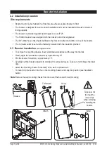
This appliance is intended for use with the Zip HydroTap
®
G4 Command-Centre
TM
Note 2
Water connections must be pointing vertically upwards.
Note 3
The booster unit should be installed as close as possible to the Zip HydroTap
®
G4 as the 500mm
connection hoses cannot be lengthened.
Booster system
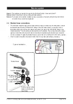
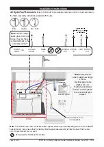
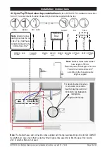
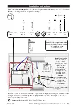
2.4 Braided hose connections
•
The cold water inlet (blue cap) and hot water outlet (red cap) are marked on the rating plate. Connect
the braided hoses from the ‘BYPASS OUT’ fitting on the Command-Centre
TM
to the water inlet of
the booster (blue cap) and from the outlet of the booster (red cap) to the ‘BYPASS IN’ fitting on the
Command-Centre
TM
. Avoid exerting mechanical force on the booster. This can be achieved by using a
spanner on the flats of the inlet and outlet connections when tightening the braided hose connectors.
Do not over-tighten ! Tighten the braided hoses by hand, then turn a further 90
O
to
180
O
with a spanner.
•
Once the water connections have been made, check for any leaks and rectify as necessary.
Strainer
Cold water connection
(inlet, 3/8” BSP)
Hold the hexagon while
tightening the braided
hose fittings
Braided hoses
Typical installation
Hot water connection
(outlet, 3/8” BSP)


