background image

801314UK - G4 Boiling chilled commercial installation instructions - June 2016 -  V2.04 

Page 21 of 28


 Installation instructions

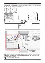
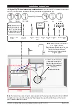
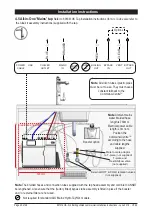
4.6 All-in-One 'Vented' tap 

Refer to 803341UK Tap installation instructions (for Arc / Cube also refer 

to the tube kit assembly instructions) supplied with the tap.

COLD isolation valve

(not supplied)

Restrictaflow valve & T-piece

(supplied)

Male to male adaptor to 

T-piece (supplied)

535mm 

Note 

Ambient mains 

water braided hose length is 750mm.

Electrical power cable length is 3m nom.

Position the Command-Centre

TM 

according to the hose and cable lengths 

supplied.

Note

 All silicon tubes 

/ plastic pipes must be 

cut to size. They must 

have a constant fall back 

to the 

Command-Centre

TM

HydroTap 

AIO Mixer

 Connections

Options

RED

CLEAR

BLUE

BRAIDED

POWER

CABLE

USB

CHILLED 

OUTLET

MAINS 

IN

MIXER 

OUT

MIXER 

IN

BOILING 

OUT

BYPASS 

IN

VENT BYPASS 

OUT

Note

 The braided hoses and connection tubes supplied with the tap head assembly and cold inlet CANNOT 

be lengthened.  Also ensure that the (factory fitted) bypass tube assembly is fitted in place if the booster  

and / or external filter are not used.

Clearance envelope

535mm

Booster 

option

External 

filter option

Summary of Contents for HydroTap G4 Series

Page 1: ...June 2016 V2 04 Page 1 of 28 Zip HydroTap G4 Installation instructions Affix model number label here 801314UK Filtered boiling and chilled drinking water for commercial kitchens and tea rooms VENTILAT...

Page 2: ...stomer s needs Classic HydroTap G4 range Arc Cube range Elite range All in One range Mixer range These standalone taps are directly compatible with the G4 Command CentreTM The All in One tap may be us...

Page 3: ...equired Section 2 Booster installation 2 1 Booster specifications and descriptions 13 2 2 Installation procedure 14 2 3 Booster installation 14 2 4 Braided hose connections 15 Section 3 Filter softene...

Page 4: ...supporting the Command CentreTM is adequate for its total weight when full of water Before commissioning Check the system has been installed correctly Check all plumbing fittings have been tightened...

Page 5: ...the water The boiling and chilled models will dispense boiling water factory set to 98 C chilled water factory set to 5 9 C These units are NOT designed to be used as sanitary fixtures The Zip HydroTa...

Page 6: ...or boiling water droplets may discharge through a vent outlet on the tap If the tap is not installed using the font ensure the tap body is located so the tap outlet safely dispenses into the sink bowl...

Page 7: ...rranty coverage As the installer it is your responsibility to supply if necessary and install all valves as required by local regulations and relevant standards The HydroTap G4 is rated for 230V 50Hz...

Page 8: ...allation instructions A potable water supply connection with isolating valve inside the cupboard within reach of the flexible braided hose and positioned so that the connection point and the stop cock...

Page 9: ...red with booster 240 175 yes 2x13A 2 20 2 20 450 x 470 x 335 28 Min Max water supply pressure HydroTaps and Mains All in One taps 0 17 MPa 1 7 bar 0 7 MPa 7 bar Mixer taps and Vented All in One taps 0...

Page 10: ...for the booster Both the Command CentreTM and booster must be installed in accordance with IEE regulations See Technical specification page 9 for power ratings Note Check all cable and hose lengths ag...

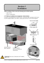
Page 11: ...let vent B Air inlet vent 1 1 Preferred ventilation arrangement shown below The ducted vent kit supplied with the Command CentreTM exhausting through the kick space should be used to provide adequate...

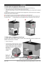
Page 12: ...nd CentreTM B Fan kit fitted to cupboard door position B1 or side position B2 and without kick space duct fitted to the Command CentreTM For dual exhaust fan cut out dimensions see the instructions pr...

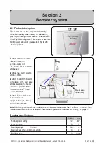
Page 13: ...m Mount base horizontally 2 1 Product description The booster system is a compact electronically controlled auxiliary water heater It is intended to provide pre heating of water before it enters the Z...

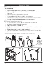
Page 14: ...ter outlet hose must be thermally insulated with the insulation provided Tilt forward Lift up Release Note Remove the wall mounting chassis from the rear of the booster for wall mounting Take care not...

Page 15: ...oses from the BYPASS OUT fitting on the Command CentreTM to the water inlet of the booster blue cap and from the outlet of the booster red cap to the BYPASS IN fitting on the Command CentreTM Avoid ex...

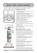
Page 16: ...etroleum products to lubricate the o rings Install cartridge with a quarter turn anticlockwise until cartridge comes to a complete stop Cartridge installation is complete Note The following instructio...

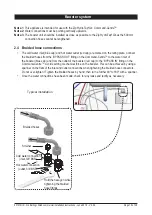
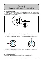
Page 17: ...g in place Section 4 Command CentreTM installation If no external filter is installed select position A A Rotate 90 only 1 2 3 4 4 1 External bypass valve The diverter bypass valve allows the user to...

Page 18: ...e assembly is fitted in place if the booster and or external filter are not used Not required for HydroTap G4 models Note Ambient mains water braided hose length is 750mm Electrical power cable length...

Page 19: ...pipes must be cut to size They must have a constant fall back to the Command CentreTM Clearance envelope 535mm 535mm CHILLED OUTLET MAINS IN MIXER OUT MIXER IN BOILING OUT BYPASS IN VENT BYPASS OUT Op...

Page 20: ...ble length is 3m nom Position the Command CentreTM according to the hose and cable lengths supplied Note All silicon tubes plastic pipes must be cut to size They must have a constant fall back to the...

Page 21: ...ngth is 3m nom Position the Command CentreTM according to the hose and cable lengths supplied Note All silicon tubes plastic pipes must be cut to size They must have a constant fall back to the Comman...

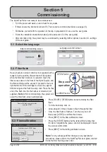
Page 22: ...cket or container not supplied Note At first commissioning the system will select the filter flush screen automatically 5 2 Filter flush Prepare filter flush as per instructions and press START Boilin...

Page 23: ...ress the MENU button for main menu Press the Install button Press the Boost button In the next screen select YES to enable the booster Before connecting the power to the booster water must be run thro...

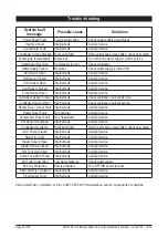
Page 24: ...Sensor Closed Internal fault Check ventilation call Zip Service Condenser Sensor Open Internal fault Check ventilation call Zip service Heater Fuse Driver Fault Internal fault Call Zip Service Heater...

Page 25: ...ce provider or the cost of removal cartage and re installation of any component of the appliance if it needs to be returned for repair to Zip or its distributor This warranty does not cover damage res...

Page 26: ...Page 26 of 28 801314UK G4 Boiling chilled commercial installation instructions June 2016 V2 04 Notes...

Page 27: ...801314UK G4 Boiling chilled commercial installation instructions June 2016 V2 04 Page 27 of 28 Notes...

Page 28: ...s of Zip Heaters Aust Pty Ltd Zip products described in this publication are manufactured under one or more of the following patents AU675601 AU637412 AU635979 GB0422305 GB2065848 US4354049 US5103859...

Reviews: