JOHNSON CONTROLS
43
SECTION 2 – OPTIVIEW CONTROL CENTER
FORM 160.69-O1
ISSUE DATE: 9/30/2012
2
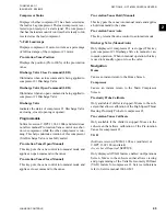
Discharge Temperature
Displays the temperature of the refrigerant in its gas-
eous state at the discharge of the compressor #1 as it
travels to the condenser.
Discharge Superheat
Displays compressor #1 discharge superheat, calcu-
lated as (discharge temperature – condenser saturation
temperature).
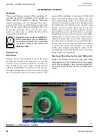
Compressor 2
Oil Pressure
Displays the pressure differential between the Pump
Oil Pressure transducer for compressor #2 and the com-
mon Sump oil pressure transducer. If either of these
transducers are out of range, the display field will show
XX.X PSID. The displayed value includes the offset
pressure derived from auto-zeroing during the system
pre-lube period. The offset pressure is the pressure
differential between compressor #2 Pump Oil Pres-
sure Transducer and the Sump Oil Pressure transducer
outputs during a three (3) second period beginning ten
(10) seconds into the system pre-lube period. During
this time, the transducers are sensing the same pres-
sure and their outputs should indicate the same pres-
sure. However, due to accuracy tolerances in transduc-
ers, differences can exist. Therefore, to compensate for
differences between transducers and assure differential
pressure sensing accuracy, the offset pressure is sub-
tracted algebraically from the differential pressure. The
offset pressure calculation is not performed if either
transducer is out of range. The offset value is taken as
0 PSI in this instance. If compressor #1 is already run-
ning when bringing compressor #2 online, the offset
calculation used will be that which was calculated dur-
ing compressor #1 pre-lube.
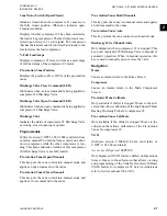
Discharge Temperature
Displays the temperature of the refrigerant in its gas-
eous state at the discharge of the compressor #2 as it
travels to the condenser.
Discharge Superheat
Displays compressor #2 discharge superheat, calcu-
lated as (discharge temperature – condenser saturation
temperature).
Programmable
None
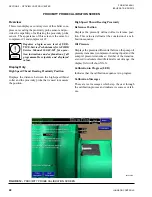
Navigation
Home
Access Level Required:
VIEW
Causes an instant return to the Home Screen.
Compressor 1
Access Level Required:
SERVICE
Only displayed in Service access level. Moves to a sub-
screen that allows calibration of the Proximity Probe
and Pre-rotational Vanes and viewing of parameters for
compressor #1. Also, manual control of the Discharge
Valve and Pre-rotation Vanes is performed on this
screen. Service Technicians refer to Service Manual
160.69-M1.
Compressor 2
Access Level Required:
SERVICE
Only displayed in Service access level. Moves to a sub-
screen that allows calibration of the Proximity Probe
and Pre-rotational Vanes and viewing of parameters for
compressor #2. Also, manual control of the Discharge
Valve and Pre-rotation Vanes is performed on this
screen. Service Technicians refer to Service Manual
160.69-M1.
Hot Gas
Access Level Required:
SERVICE
Moves to a subscreen that allows programming of the
Hot Gas Bypass control setpoints and manual control
of the Hot Gas Bypass valve. Only displayed if in Ser-
vice access level and the Hot Gas feature is enabled on
the OPERATIONS Screen. Service Technicians refer
to Service Manual 160.69-M1.
Surge
Access Level Required:
VIEW
Moves to a subscreen that allows viewing and program-
ming of the Surge Protection feature. Service Techni-
cians refer to Service manual 160.69-M1.
Compressor Capacity Cycling
Access Level Required:
VIEW
Moves to a subscreen that allows viewing and pro-
gramming of the compressor cycling setup setpoints.
Service Technicians refer to Service Manual 160.69-
M1.

