JOHNSON CONTROLS
16
FORM 160.69-O1
ISSUE DATE: 9/30/2012
SECTION 1 – DESCRIPTION OF SYSTEM AND FUNDAMENTALS OF OPERATION
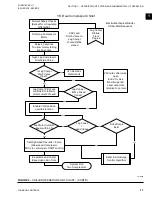
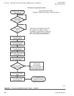
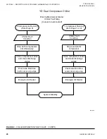
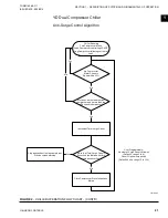
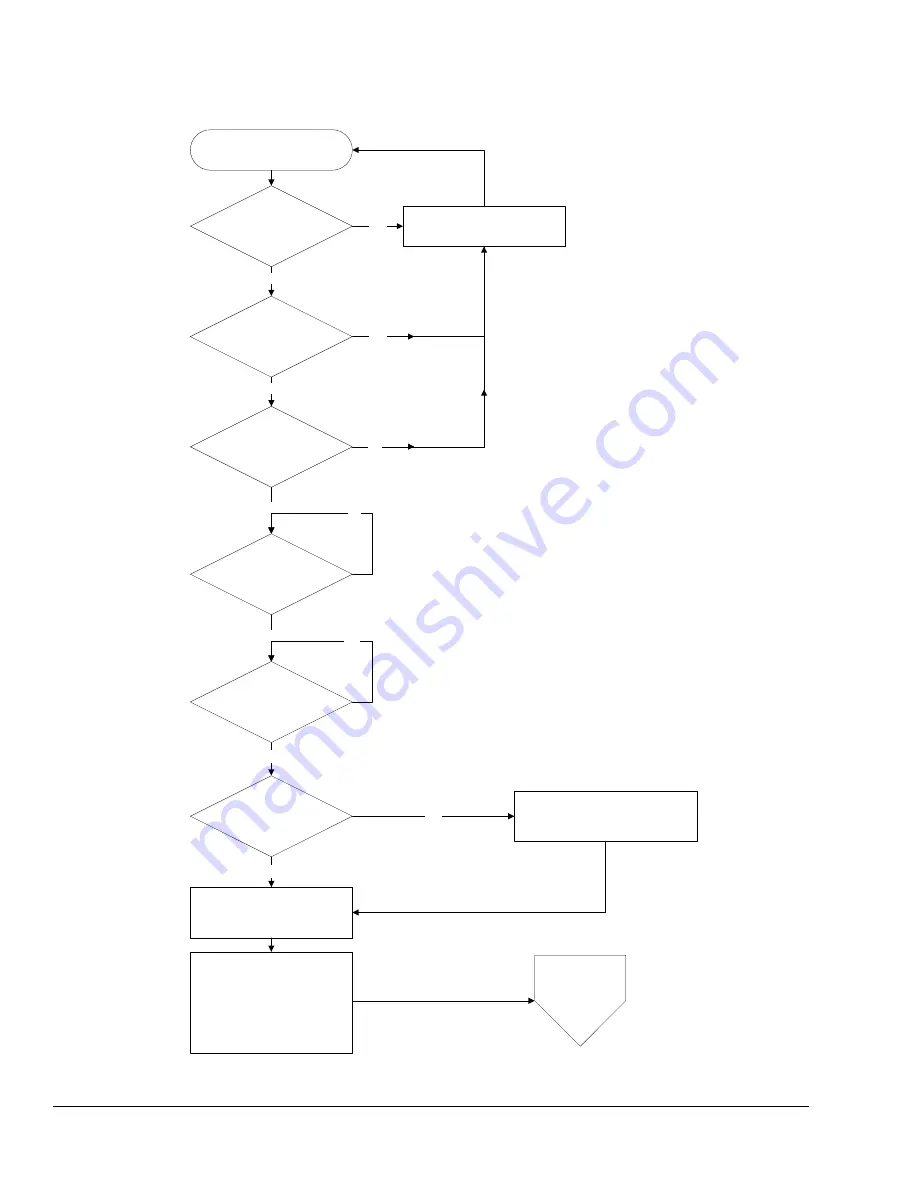
FIGURE 2
– CHILLER OPERATION FLOW CHART - (CONT'D)
1 compressor running
(from Page 1)
Is La
Single
Compressor Mode?
Lead
Compressor
Pulldown Time
Elapsed?
g
Compressor in
Service Lockout
Electro-Mechanical Starter
Chiller Start Sequence
Don't start lag compressor
Yes
Yes
Is Leaving ChW
Temp > setpoint?
(Timer)
Is
Lag Compressor
Ready to Start
Yes
Yes
Yes
NO
No
No
Pre-Lube Lag Oil Pump
(Don't auto-zero oil
pressure transducers)
No
No
2n
Trend rate of pull
down on startup to
decide on
d
compr
(Antirecycle
time met)
Ready to Start
Lag
Transition Period
Level Control Settings for
2 compressor start
Pulse VO valve open only
5 sec every 10 sec to
maintain Liq. Level < 20%
Is Diff.Press/P > 1.6
(High Head)
No
Close Signal to
Lead Compressor PRV’s
(High Head Override = True)
Yes
Unload Lead
compressor on high
head operation
Lag Compr
Startup
Continued
Page 3
D.P./P is
programmable
YD Dual Compressor Chiller
LD10488a


