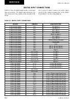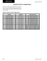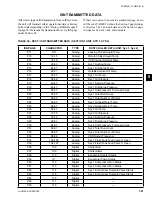
312
JOHNSON CONTROLS
FORM 201.21-NM3 (616)
MICRO PANEL
ANALOG INPUT CONNECTIONS
TABLE 21 lists the Analog inputs and the circuit board
they are located on. Not all of the sensors are installed in
every unit, as some of them are optional. The software
must read the optional sensors if installed. The Analog
input signals are typically referenced to the common
(return, ground) in the system.
J12-3 can also be used as common, as well as chassis
ground, or the common terminal point on the Chiller
Control Board. See the wiring diagrams. The +DC Bus,
-DC Bus and ½ DC Bus voltages are measured in refer-
ence to one of the other DC Bus points. For example:
+DC Bus measured to ½ DC Bus.
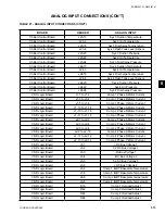
TABLE 21 - ANALOG INPUT CONNECTIONS
BOARD
HEADER
ANALOG INPUT
Chiller Control Board
J17-11
Remote Temperature Reset
Chiller Control Board
J17-12
Remote Current Limit
Chiller Control Board
J17-13
Spare 1
Chiller Control Board
J17-14
Spare 2
Chiller Control Board
J17-15
Spare 3
Chiller Control Board
J8-7
Leaving Chilled Liquid Temp Sensor
Chiller Control Board
J8-8
Return Chilled Liquid Temp Sensor
Chiller Control Board
J8-9
Ambient Air Temp Sensor
Chiller Control Board
J19-1
Comp 1 Motor Temperature 1
Chiller Control Board
J19-2
Comp 1 Motor Temperature 2
Chiller Control Board
J19-3
Comp 1 Motor Temperature 3
Chiller Control Board
J19-6
Comp 2 Motor Temperature 1
Chiller Control Board
J19-7
Comp 2 Motor Temperature 2
Chiller Control Board
J19-8
Comp 2 Motor Temperature 3
Chiller Control Board
J21-13
Sys 1 Suction Temperature
Chiller Control Board
J21-3
Sys 1 Oil Temperature
Chiller Control Board
J21-16
Sys 1 Discharge Temperature
Chiller Control Board
J21-6
Sys 1 Flash Tank Level Sensor
Chiller Control Board
J21-20
Sys 1 Suction Pressure
Chiller Control Board
J21-22
Sys 1 Oil Pressure
Chiller Control Board
J21-24
Sys 1 Discharge Pressure
Chiller Control Board
J22-13
Sys 2 Suction Temperature
Chiller Control Board
J22-2
Sys 2 Oil Temperature
Chiller Control Board
J22-16
Sys 2 Discharge Temperature
Chiller Control Board
J22-6
Sys 2 Flash Tank Level Sensor
Chiller Control Board
J22-20
Sys 2 Suction Pressure
Chiller Control Board
J22-22
Sys 2 Oil Pressure
Chiller Control Board
J22-24
Sys 2 Discharge Pressure
Chiller Control Board
J20-1
Comp 3 Motor Temperature 1
Chiller Control Board
J20-2
Comp 3 Motor Temperature 2
Chiller Control Board
J20-3
Comp 3 Motor Temperature 3
Chiller Control Board
J20-6
Comp 4 Motor Temperature 1
Chiller Control Board
J20-7
Comp 4 Motor Temperature 2
Chiller Control Board
J20-8
Comp 4 Motor Temperature
Summary of Contents for YCAV0267E
Page 61: ...61 JOHNSON CONTROLS FORM 201 21 NM3 616 This intentionally left blank 6 ...
Page 73: ...73 JOHNSON CONTROLS FORM 201 21 NM3 616 This page intentionally left blank 6 ...
Page 89: ...89 JOHNSON CONTROLS FORM 201 21 NM3 616 6 035 20890 009 REV LOCATION LABEL CON T LD11141 ...
Page 146: ...146 JOHNSON CONTROLS FORM 201 21 NM3 616 TECHNICAL DATA This page intentionally left blank ...
Page 147: ...147 JOHNSON CONTROLS FORM 201 21 NM3 616 6 This page intentionally left blank ...
Page 247: ...247 JOHNSON CONTROLS FORM 201 21 NM3 616 This page intentionally left blank ...
Page 269: ...269 JOHNSON CONTROLS FORM 201 21 NM3 616 This page intentionally left blank 8 ...
Page 289: ...289 JOHNSON CONTROLS FORM 201 21 NM3 616 8 This page intentionally left blank ...
Page 317: ...317 JOHNSON CONTROLS FORM 201 21 NM3 616 8 This page intentionally left blank ...
Page 348: ...348 JOHNSON CONTROLS FORM 201 21 NM3 616 MAINTENANCE NOTES ...
Page 349: ...349 JOHNSON CONTROLS FORM 201 21 NM3 616 9 NOTES ...


