212
JOHNSON CONTROLS
FORM 201.21-NM3 (616)
STANDARD IPLV CAPACITY CONTROL
(Loading/Unloading and starting additional compressors)
“Standard IPLV” Capacity Control is installed in
the chiller at the factory using a dedicated EPROM
(software), part # 031-02476-001, for “Standard Only”
IPLV control. If the LCHLT is > the programmed
Se CR, only a single compressor is permitted to
start under standard IPLV control. The compressor will
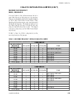
start at the minimum start frequency based on ambient
temperature (Page 210). The lead compressor Feed and
Drain Valves will immediately begin to control superheat
and liquid level in the Flash Tank.
When a compressor starts, the load and unload timers
will be set to 30 seconds. During the first 30 seconds of
operation after a compressor reaches the start frequency,
loading/unloading is inhibited.
After 30 seconds, the control logic looks at the LCHLT
temp, compares it to the Setpoint plus CR, and makes
decisions to load or unload.
For precise capacity control, the Chiller Control Board
microprocessor loads and unloads compressors quickly,
as fast as every 2 seconds, in increments of 0.1-1 Hz each
time a load or unload change is required. Fixed load and
unload timers of 2 sec. are set, after a speed change of
0.1-1 Hz, to minimize undershoot and overshoot.
As additional cooling is required (LCHLT > Setpoint
+ CR), the Chiller Control Board microprocessor will
increase the speed of the compressor at the rate of 0.1-1
Hz every 2 seconds until the load is satisfied. Loading
will continue to occur as long as leaving chilled liquid
temperature is above the Se CR.
If the temperature falls very near or within the control
range, the Chiller Control Board microprocessor will
make decisions regarding speed changes under condi-
tions where the “error” and “rate” conflict. Under these
conditions, loading/unloading follows the guidelines
described in the Fuzzy Logic Control Section (Page
213).
If the compressor speed exceeds the maximum
frequency the compressor is allowed to operate minus
1 hertz for a period of 3 minutes without bringing the
leaving chilled liquid temperature to within Se
CR/2, the chiller control will make a decision to start
another compressor. At this point, the first compressor
will decelerate to a frequency of 5 Hz. Reducing the
frequency of the running compressor to 5 Hz enables
the differential between discharge and suction pres-
sure to be reduced to a point where it will not affect
motor current when the running compressor is ramped
up. It also reduces the possibility of backspin on the
running compressor. The next lag compressor will be
activated and all compressors will be accelerated to the
START FREQ. The START FREQ is specified by the
formula:
START FREQ = Current VSD Freq x (Number of Compressor enabled -1)
Number of Compressors enabled
For example: Current VSD Freq = max freq of the chiller = 200 Hz.
Number of compressors enabled = 2 = Original
compressor running, plus the compressor to be added.
In this example, assume a single compressor had
been running at the max frequency of 200 Hz without
satisfying cooling demand. (2) compressors are now
enabled when the second compressor is activated. Plac-
ing these values in the formula, the START Frequency
= 200 Hz x (2-1)/2 = 100 Hz. The compressors will be
accelerated to a start frequency of 100 Hz. Load and
unload timers will be set to 30 seconds. The anti-recycle
timer will be set to 120 seconds.
If additional cooling is required, after the initial 30 sec-
onds of operation, loading will occur at the rate of 0.1 -1
Hz every 2 seconds, unless load limiting occurs.
If the cooling capacity exceeds the demand and tem-
perature continues to drop while in the CONTROL
RANGE (CR) with multiple compressors operating,
the Chiller Control Board microprocessor will decrease
the speed of the compressor(s) at the rate of 0.1-1 Hz
every 2 seconds until the LCHLT stabilizes within the
CONTROL RANGE. If frequency (speed) drops below
the LESS COMP FREQ – 20 Hz or the minimum VSD
frequency, whichever is higher, the compressors will
be decelerated to a speed of 5 Hz, the last compressor
disabled, and the remaining compressor(s) restarted
minus one lag compressor. The LESS COMP FREQ
is designated as:
LESS COMP FREQ = Max VSD Freq x (Number of compressor enabled -1)
Number of Compressors enabled
For example: 200 Hz = max freq of the chiller.
Number of compressors enabled before shutdown = 2
OPERATION
Summary of Contents for YCAV0267E
Page 61: ...61 JOHNSON CONTROLS FORM 201 21 NM3 616 This intentionally left blank 6 ...
Page 73: ...73 JOHNSON CONTROLS FORM 201 21 NM3 616 This page intentionally left blank 6 ...
Page 89: ...89 JOHNSON CONTROLS FORM 201 21 NM3 616 6 035 20890 009 REV LOCATION LABEL CON T LD11141 ...
Page 146: ...146 JOHNSON CONTROLS FORM 201 21 NM3 616 TECHNICAL DATA This page intentionally left blank ...
Page 147: ...147 JOHNSON CONTROLS FORM 201 21 NM3 616 6 This page intentionally left blank ...
Page 247: ...247 JOHNSON CONTROLS FORM 201 21 NM3 616 This page intentionally left blank ...
Page 269: ...269 JOHNSON CONTROLS FORM 201 21 NM3 616 This page intentionally left blank 8 ...
Page 289: ...289 JOHNSON CONTROLS FORM 201 21 NM3 616 8 This page intentionally left blank ...
Page 317: ...317 JOHNSON CONTROLS FORM 201 21 NM3 616 8 This page intentionally left blank ...
Page 348: ...348 JOHNSON CONTROLS FORM 201 21 NM3 616 MAINTENANCE NOTES ...
Page 349: ...349 JOHNSON CONTROLS FORM 201 21 NM3 616 9 NOTES ...

