background image

275

JOHNSON CONTROLS

FORM 201.21-NM3 (616)

HISTORY KEY (CON'T)

UNIT DATA

Evaporator Leaving and Return Chilled Liquid
Temps

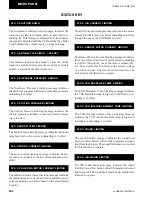
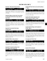
This message indicates the leaving and entering chilled 

liquid temperatures at the time of the fault.

Ambient Air Temperature

UNIT   CHILLED  LIQUID  LEAVING = XXX.X °F


            ENTERING = XXX.X °F

This message indicates the ambient air temperature at 

the time of the fault.

Load / Unload Timers

UNIT
  OUTSIDE  AMBIENT  AIR  TEMP = XXX.X °F

UNIT   

LOAD  TIMER = XXX SEC


         UNLOAD  TIMER = XXX SEC

This message indicates remaining time on the load and 

unload timers at the time of the fault.

Chilled Liquid Temperature Error and Rate of
Change

UNIT  ACTIVE  REMOTE  CONTR0L = XXXXXX

UNIT   

EVAP  PUMP  RUN = XXX


     EVAP  HEATER = XXX

UNIT  SOUND  LIMIT 

   LOCAL = XXX %


ISN = XXX 

REMOTE = XXX %

VSD  FREQUENCY 

ACTUAL = XXX.X HZ


          COMMAND = XXX.X HZ 

UNIT   

TEMP  ERROR = XXX.X °F


 RATE = XXX.X °F/M

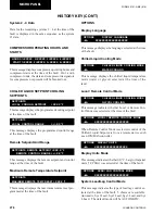
This message indicates the temperature error between 

the actual and the programmed setpoint at the time of 

the fault and the rate of temperature change.

Programmed Lead System Selection and 
Flow Switch Status

This message indicates the designated lead system at the 

time of the fault and whether the flow switch was ON 

(Closed) or OFF (Open) at the time of the fault.

UNIT  LEAD  SYSTEM  NUMBER = X


   FLOW  SWITCH = XXX

Evaporator Pump and Evaporator Heater 
Status

This message indicates the status of the evaporator pump 

and the evaporator heater at the time of the fault. XXX 

indicates ON or OFF.

Active Remote Control Status

This message indicates whether the system was operat-

ing under active remote control  (RCC, ISN, LOAD, 

TEMP, or SOUND) or standard control (NONE) at the 

time of the fault.

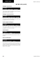
This message indicates that sound limiting was in ef-

fect, the amount, and whether it was local or remotely 

limited.  

VSD DATA

VSD Actual and Command Frequency

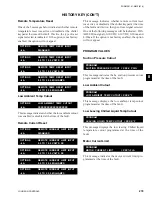
This message indicates the VSD actual operating 

frequency and the command frequency at the time of 

the fault.  Actual and command may not match due to 

load/unload timers, limitation of 1 Hz per load/unload 

increment, and to allowable acceleration/deceleration 

of the motor. 

VSD  COMP  1 = XXX  AMPS 

= XXX %FLA

 COMP  2 = XXX  AMPS   

= XXX %FLA

Compressor AMPS and %FLA

The message indicates the compressor %FLA and cur-

rents for systems 1 and 2 at the time of the fault.  

8

Summary of Contents for YCAV0267E

Page 1: ...NS AIR COOLED SCREW LIQUID CHILLERS E V HIGH EFFICIENCY AND S P STANDARD EFFICIENCY 50075 AIR COOLED SCREW LIQUID CHILLERS INSTALLATION OPERATION MAINTENANCE Supersedes 201 21 NM3 315 Form 201 21 NM3 616 035 20994 000 R134a Issue Date June 30 2016 ...

Page 2: ...ument and any referenced materials This in dividual shall also be familiar with and comply with all applicable industry and governmental standards and regulations pertaining to the task in question SAFETY SYMBOLS The following symbols are used in this document to alert the reader to specific situations Indicates a possible hazardous situation which will result in death or serious injury if proper ...

Page 3: ...he inductor with power off WARNING CHANGEABILITY OF THIS DOCUMENT In complying with Johnson Controls policy for con tinuous product improvement the information con tained in this document is subject to change without notice Johnson Controls makes no commitment to update or provide current information automatically to the manual or product owner Updated manuals if applicable can be obtained by cont...

Page 4: ...utomation System BAS Interface 19 Condensor Coil Protection 19 DX COOLER OPTIONS 20 SERVICE VALVE OPTION 20 UNIT ENCLOSURES 20 FANS 20 SOUND REDUCTION OPTIONS 20 VIBRATION ISOLATION 20 UNIT NOMENCLATURE 21 PRODUCT IDENTIFICATION NUMBER 22 SECTION 3 RIGGING HANDLING AND STORAGE DELIVERY AND STORAGE 26 INSPECTION 26 MOVING THE CHILLER 26 Lifting Weights 26 UNIT RIGGING 27 SECTION 4 INSTALLATION LOCA...

Page 5: ...SMIC ISOLATOR INSTALLATION 163 NEOPRENE ISOLATOR POSITION 164 1 DEFLECTION ISOLATOR INSTALLATION 165 REFRIGERANT FLOW DIAGRAM 167 PROCESS INSTRUMENTATION DIAGRAM 168 COMPONENT LOCATIONS 169 EQUIPMENT START UP CHECK SHEET 188 Unit Checks NO power 188 Panel Checks Power ON both system switches OFF 190 Programmed Values 191 Chilled Liquid Setpoint 191 Date Time Daily Schedule Clock Jumper 191 Initial...

Page 6: ...T RESET 230 Sound Limit Controls 232 SECTION 8 MICROPANEL VSD OPERATION CONTROLS 234 VSD Cooling and Cooling Loop 236 VSD SAFETIES 240 IGBT Gate Driver Hardware Fault 243 Power Supply Hardware Fault 245 UNIT WARNINGS 248 UNIT SAFETIES 252 SYSTEM SAFETIES 254 STATUS KEY 260 UNIT DATA KEY 264 SYSTEM DATA KEY 266 VSD DATA KEY 270 OPERATING HOURS START KEYS 272 HISTORY KEY 273 Unit Data 274 VSD Data 2...

Page 7: ...vs Error 217 Table 6 Current Load Limiting Unloading 218 Table 7 Discharge Pressure Load Limiting Unloading 218 Table 8 Suction Pressure Load Limiting Unloading 219 Table 9 VSD Internal Ambient Load Limiting Unloading 219 Table 10 VSD Baseplate Temperature Load Limiting Unloading 220 Table 11 Fan Stages Corresponding Outputs 225 Table 12 VSD Operating Display Parameters 239 Table 13 Low Differenti...

Page 8: ...16 Control and VSD Cabinet Locations 170 Fig 17 Chiller Control Board Relay Boards Microgateway and Optional Circuit Breaker 171 Fig 18 Chiller Control Board Relay Boards and Microgateway 172 Fig 19 VSD Logic Board 173 Fig 20 VSD Logic Board 173 Fig 21 Power Components 175 Fig 22 Power Components 175 Fig 23 Fan Contactors 177 Fig 24 VSD Components 178 Fig 25 VSD Components 179 Fig 26 VSD Component...

Page 9: ...y part or sub assembly which has failed due to poor quality or manufacturing errors All claims must be supported by evidence that the failure has occurred within the warranty period and that the unit has been operated within the designed parameters specified All warranty claims must specify the unit model serial number order number and run hours starts Model and serial number information is printe...

Page 10: ...s manual and any other document supplied with the unit are the property ofYORK which reserves all rights They may not be reproduced in whole or in part without prior written authorization from an authorized YORK representative MISUSE OF EQUIPMENT Suitability for Application The unit is intended for cooling water or glycol solu tions and is not suitable for purposes other than those specified in th...

Page 11: ...e taken when working in contact with the coils to avoid the risk of minor abrasions and lacerations The use of gloves is recommended Frame rails brakes and other components may also have sharp edges Reasonable care should be taken when working in contact with any components to avoid risk of minor abrasions and lacerations Refrigerants and Oils Refrigerants and oils used in the unit are generally n...

Page 12: ...eral System Description The Latitude YCAV Air Cooled Chiller line combines the best of modern screw compressor design with the latest technology in variable speed drives The result is superior control and efficiency in real world conditions TheVSD enables slowing the speed of the compressor to match the load on the system resulting in precise chilled liquid control minimized sound maximum energy e...

Page 13: ...CONTROL SYSTEM INPUTS COMMUNICATIONS OUTPUTS VSD MOTOR CONTROL PANEL Pressure Transducers Temperature Sensors Level Sensor Switches Liquid Flow High Pressure Start Stop Customer Supplied Contacts Chiller Control Board Microprocessor User Interface Display Keypad Building Automation Printer Modem VSD Logic Board SCR Trigger Board Power Components PWM Speed Control Relay Output Board Solenoids Conta...

Page 14: ...t and insulated with 3 4 19 mm flexible closed cell insulation The water nozzles are provided with grooves for mechanical couplings and should be insulated by the contractor after pipe installation A 300 PSIG 20 7 bar waterside design working pres sure option is available 2 compressor chillers utilize a typical 2 pass E type evaporator with liquid inlets and suction outlets at the same end Enterin...

Page 15: ...r solenoid valve will typically be on most of the time When the economizer solenoid is OFF the liquid level will vary greatly as the Drain and Feed Valves directly affect the level as they open and close Oil Separator Oil System The external oil separators with no moving parts and designed for minimum oil carry over are mounted in the discharge line of the compressor The high pressure discharge ga...

Page 16: ...Each Power Compartment Contains Incoming single point power is standard utilizing either a lockable circuit breaker or terminal block 115VAC control transformer VSD fan contactors ON OFF unit switch microcomputer keypad and display Chiller Con trol and VSD Logic boards 1 or 2 SCR trigger control boards and relay boards Current transformers sense each phase of motor current and send corresponding s...

Page 17: ...er pump Out of range message Up to 10 fault shutdown histories Keypad An operator keypad allows complete control of the system from a central location The keypad utilizes an overlay to allow use in 5 languages The keypad is a color coded 36 button sealed keypad with keys for Display Entry Setpoints Clock Print Program Unit ON OFF and other functions Details on a few of the keys follow Status Allow...

Page 18: ...er while simultaneously providing a large energy reservoir for use by the DC to AC inverter section of the drive In order to achieve the required voltage capability for the capacitor portion of the filter filter capacitor banks are formed by connecting two groups of parallel capacitors in series to form a capaci tor bank In order to assure an equal sharing of the voltage between the series connect...

Page 19: ...gic board Each IGBT Power Module within the DC toAC inverter section con tains a thermistor heatsink temperature sensor to provide temperature information to the VSD logic board The Bus Isolator board utilizes three resistors on the board to provide a safe impedance resistance between the DC link filter capacitors located on the output phase bank assemblies and the VSD logic board It provides the ...

Page 20: ...rior condenser coil faces and heavy gauge welded wire mesh guards mounted around the bottom of the unit Factory or field mounted Louvered Panels Condenser Coils Only Louvered panels are mounted over the exterior condenser coil faces on the sides of the unit to visually screen and protect the coils Factory or field mounted Louvered Panels Full Unit enclosure Louvered panels over condenser coils and...

Page 21: ...R COOLED VSD DRIVEN SCREW COMPRESSOR MODEL NUMBER UNIT DESIGNATOR E High Efficiency with Standard IPLV S Standard Efficiency with Standard IPLV P Standard Efficiency with High IPLV V High Efficiency with High IPLV REFRIGERANT R134a VOLTAGE CODE STARTER VSD DESIGN SERIES DEVELOPMENT CODE VOLTAGE CODE UNIT DESIGNATOR 17 200 3 60 28 230 3 60 40 380 3 60 46 460 3 60 50 380 400 415 3 50 58 575 3 60 ...

Page 22: ... 0969 0969 1039 1039 1139 1139 1169 1169 1309 1309 1429 1429 1549 1549 1649 1649 1739 1739 1829 1829 1909 1909 UNIT Unit Designator PIN 9 S Standard Efficiency Standard IPLV P Standard Efficiency Optimized IPLV E High Efficiency High Ambient Unit Standard IPLV V High Efficiency High Ambient Unit Optimized IPLV REF Refrigerant PIN 10 A R 134a VOLTS Voltage PIN 11 12 17 200 3 60 28 230 3 60 40 380 3...

Page 23: ...LCD Keypad Display G German LCD Keypad Display I Italian LCD Keypad Display P Portuguese LCD Keypad Display Q Special LCD Keypad Display RDOUT Silent Night PIN 23 X No option required N Silent Night sound limiting control option Q Special quote SAFETY Safety Code PIN 24 L Std 60 Hz N American Safety Code cUL cETL N Std 50 HZ No listing Q Special Safety Code SENSOR PIN 25 X No option required Q Spe...

Page 24: ... required Q Special quote X Aluminum Coils COILS Coils PIN 45 C Copper Fin Coils B Pre Coated Fin Coils P Post Coated Dipped Coils Q Special Coils HEAT Heat Recovery PIN 46 X Partial Heat Recovery not required H Partial Heat Recovery required Q Special quote FANMOTORS Fan Motors PIN 47 X TEAO Fan Motors Q Special Fan Motors PANEL Enclosure Panels PIN 48 X No Enclosure Panels required 1 Wire Full U...

Page 25: ... 1 Deflection Isolators required S Seismic Isolators required N Neoprene Pad Isolators required Q Special Vibration Isolators required WARRANTY Warranty PIN 55 X 1st Year Parts Only Std Warranty B 1st Year Parts Labor C 2nd Year Parts Only D 2nd Year Parts Labor E 5 Year Compressor Parts Only F 5 Year Compressor Parts Labor G 5 Year Unit Parts Only H 5 Year Unit Parts Labor Q Special Warranty REFR...

Page 26: ... and fins from potential damage and corrosion particularly where building work is in progress The unit should be stored in a location where there is minimal activity in order to limit the risk of ac cidental physical damage To prevent inadvertent operation of the pressure relief devices the unit must not be steam cleaned It is recommended that the unit is periodically in spected during storage INS...

Page 27: ...g locations are outside of the container Place 4 X 4 blocks of wood under the base rails of the unit Gently rest the unit on the blocks and remove the chains and lift truck 5 Attach lifting rigging from the crane and slowly complete the removal from the container then lift up and away LD19197a LIFTING USING LUGS Units are provided with lifting holes in the base frame which accept the accessory lif...

Page 28: ...1 9 Y 300 4 Y 370 7 Y 477 2 Y 513 9 HIGH EFF 0357 1309 Y 11 5 Y 88 3 Y 171 3 Y 254 1 Y 370 3 Y 451 5 0327 1169 Y 11 5 Y 88 3 Y 171 3 Y 254 1 Y 326 3 Y 407 5 0267 1039 Y 11 5 Y 88 3 Y 176 3 Y 264 3 Y 326 3 Y 407 5 0287 0969 Y 11 5 Y 88 3 Y 176 3 Y 264 3 Y 320 0 Y 363 9 0477 1739 Y 11 5 Y 103 1 Y 150 6 Y 201 7 Y 301 9 Y 370 7 Y 477 2 Y 557 9 0417 1549 Y 11 5 Y 103 1 Y 150 6 Y 201 7 Y 301 9 Y 370 7 Y...

Page 29: ...ending below the frost line is recommended To avoid noise and vibration transmission the unit should not be secured to the building foundation On rooftop locations choose a place with adequate structural strength to safely support the entire operating weight of the unit and service personnel The unit can be mounted on a concrete slab similar to ground floor locations or on steel channels of suitab...

Page 30: ... of large components may require larger clearances than those given in the Technical Data Section Page 156 INSTALLATION OF VIBRATION ISOLATORS Optional sets of vibration isolators can be supplied loose with each unit Using the Isolator tables shipped with the unit in the information pack refer to the Dimension Section Pages 90 155 Weight Distribution and Isolator Mounting Position Section Pages 15...

Page 31: ...solved gases which can cause oxidation of steel parts within the cooler A flow switch must be installed in the customer pip ing at the outlet of the cooler and wired back to the control panel using shielded cable There should be a straight run of piping of at least 5 pipe diameters on either side The flow switch should be wired to Terminals 2 and 13 on the 1TB terminal block A flow switch is requi...

Page 32: ... a range between 7 and 8 5 PIPEWORK ARRANGEMENT The following is a suggested piping arrangement for single unit installations For multiple unit installations each unit should be piped as shown in FIG 3 Isolating Valve Normally Open Isolating Valve Normally Closed Flow Regulating Valve Flow Measurement Device Strainer Pressure Tapping Flow Switch Flanged Connection Pipework FIG 3 PIPEWORK ARRANGEME...

Page 33: ... the fan outlet and straight for at least three feet 1 meter to obtain static regain from the fan Ductwork should be suspended with flexible hangers to prevent noise and vibration being transmitted to the structure Aflexible joint is also recommended between the duct attached to the fan and the next section for the same reason Flexible connectors should not be allowed to concertina The unit is not...

Page 34: ...from the box to the chiller 115VAC CONTROL SUPPLY TRANSFORMER A3 wire high voltage to 115VAC supply transformer is standard in the chiller This transformer is mounted in the Cabinet and steps down the high voltage supply to 115VAC to be used by the Controls VSD Feed Drain Valve Controller valves solenoids heaters etc The high voltage for the transformer primary is taken from the chiller input Fusi...

Page 35: ...p A Remote Run Stop input is available for each pair of systems 1 3 2 4 These inputs require a dry contact to start and stop the system System 1 3 remote dry contacts are connected between Terminals 2 and 15 of 1TB and System 2 4 dry contacts are connected between Terminals 2 and 16 of 1TB If remote start stop is not utilized a jumper must be paced across the terminals to allow the system to run T...

Page 36: ...If valves are of the back seat type open them fully counterclockwise then close one turn of the stem to ensure operating pressure is fed to pressure transducers Open the liquid line service valve and oil return line ball valve fully in each system Compressor Oil To add oil to a circuit connect a YORK hand oil pump Part No 470 10654 000 to the 1 4 oil charging valve on the oil separator piping with...

Page 37: ...ly using shielded cable There should be a straight run of at least 5 pipe diam eters on either side of the flow switch The flow switch should be connected to terminals 2 and 13 in the panel Temperature Sensor s Ensure the leaving liquid temperature sensor is coated with heat conductive compound Part No 013 00890 000 and is inserted to the bottom of the water outlet sensor well in the evaporator Th...

Page 38: ...t the controller will increase the speed of the compressor s Condenser and Fan Rotation Once a compressor is running discharge pressure rises as refrigerant is pumped into the air cooled condenser coils This pressure is controlled by stages of fans to ensure maximum unit efficiency while maintaining suf ficient pressure for correct operation of the condensers and the lubrication system As discharg...

Page 39: ...SYS 1 switch on the keypad and repeat the process for each subsequent system When all run correctly stop the unit switch all applicable switches to the ON position and restart the unit Assure all checks are completed in the EQUIPMENT START UP CHECK SHEET Pages 188 193 The chiller is then ready to be placed into operation 5 ...

Page 40: ...ICAL DATA EVAP YCAV MODELS A 0267EA VA 0287SA PA 0287EA VA B 0307SA PA 0327EA VA 0357SA PA 0357EA VA 0397SA PA C 0397EA VA 0417SA PA 0457SA PA D 0417EA VA 0477EA VA 0477SA PA 0507SA PA 0527SA PA 1 10 100 100 1000 2000 A B C D WATER FLOW RATE GPM PRESSURE DROP FT H 2 0 TECHNICAL DATA ...

Page 41: ...EA VA 0287SA PA 0287EA VA B 0307SA PA 0327EA VA 0357SA PA 0357EA VA 0397SA PA C 0397EA VA 0417SA PA 0457SA PA D 0417EA VA 0477EA VA 0477SA PA 0507SA PA 0527SA PA WATER PRESSURE DROP SI 1 10 100 1000 10 0 100 0 A B C D LD11082 WATER FLOW RATE L S PRESSURE DROP kPa 6 ...

Page 42: ...e drops are higher than with water see correction factors to be applied when using glycol solutions Special care must be taken not to exceed the maximum flow rate allowed A Correction Factor B Mean Temperature through Cooler C Concentration W W Excessive flow above the max GPM will damage the evaporator PROPYLENE GLYCOL ETHYLENE GLYCOL GLYCOL CORRECTION FACTORS A A B B 18 17 16 15 14 13 12 11 10 1...

Page 43: ...125 0307 S P 40 60 300 1200 0 125 0327 E V 40 60 300 1200 0 125 0357 S P E V 40 60 300 1200 0 125 0397 S P 40 60 300 1200 0 125 0397 E V 40 60 350 1250 0 125 0417 S P 40 60 350 1250 0 125 0417 E V 40 60 400 1400 0 125 0457 S P 40 60 350 1250 0 125 0477 S P E V 40 60 400 1400 0 125 0507 S P 40 60 400 1400 0 125 0527 S P 40 60 400 1400 0 125 MODEL NUMBER YCAV LEAVING WATER TEMPERATURE C COOLER FLOW ...

Page 44: ... 4 5 5 6 6 6 6 5 5 5 5 6 5 5 5 6 5 5 5 6 6 5 6 6 6 6 6 Low Noise Fans Fan Motor HP kW 2 1 8 2 1 8 2 1 8 2 1 8 2 1 8 2 1 8 2 1 8 2 1 8 2 1 8 Fan Motor Speed revs min 1140 1140 1140 1140 1140 1140 1140 1140 1140 Fan Diameter inches 35 4 35 4 35 4 35 4 35 4 35 4 35 4 35 4 35 4 Fan Tip Speed ft min 10575 10575 10575 10575 10575 10575 10575 10575 10575 Total Chiller Airflow cfm 169000 182000 208000 234...

Page 45: ...kW 2 1 8 2 1 8 2 1 8 2 1 8 2 1 8 2 1 8 2 1 8 Fan Motor Speed revs min 1140 1140 1140 1140 1140 1140 1140 Fan Diameter inches 35 4 35 4 35 4 35 4 35 4 35 4 35 4 Fan Tip Speed ft min 10575 10575 10575 10575 10575 10575 10575 Total Chiller Airflow cfm 182000 208000 208000 234000 260000 286000 312000 Ultra Quiet Fans Fan Motor HP kW 2 1 50 2 1 50 2 1 50 2 1 50 2 1 50 2 1 50 2 1 50 Fan Motor Speed revs...

Page 46: ...69 Condenser Fans Number Ckt 1 Ckt 2 5 4 4 5 5 4 5 5 6 6 6 6 5 5 5 5 6 5 5 5 6 6 5 5 6 6 5 6 6 6 6 6 Standard Fans Fan Motor HP kW 2 1 50 2 1 50 2 1 50 2 1 50 2 1 50 2 1 50 2 1 50 2 1 50 2 1 50 Fan Motor Speed revs sec 19 19 19 19 19 19 19 19 19 Fan Diameter mm 899 2 899 2 899 2 899 2 899 2 899 2 899 2 899 2 899 2 Fan Tip Speed m sec 54 54 54 54 54 54 54 54 54 Total Chiller Airflow l sec 79768 859...

Page 47: ...669 669 669 669 669 Condenser Fans Number Ckt 1 Ckt 2 05 05 04 05 05 06 05 05 06 06 06 06 5 5 5 5 6 6 5 5 6 6 6 6 Standard Fans Fan Motor HP kW 2 1 50 2 1 50 2 1 50 2 1 50 2 1 50 2 1 50 2 1 50 Fan Motor Speed revs sec 19 19 19 19 19 19 19 Fan Diameter mm 899 2 899 2 899 2 899 2 899 2 899 2 899 2 Fan Tip Speed m sec 54 54 54 54 54 54 54 Total Chiller Airflow l sec 85904 98176 98176 110448 122720 13...

Page 48: ...48 JOHNSON CONTROLS FORM 201 21 NM3 616 OPERATING LIMITATIONS AND SOUND DATA Contact Product Application Marketing for Sound Power Data TECHNICAL DATA ...

Page 49: ...TEM COMPESSOR SWITCHES OPTION FAN CONTACTORS EVAPORATOR HEATER UNIT CONTROLS FIELD PROVIDED UNIT POWER SUPPLY VSD 1 VSD CONTROL PANEL LINE REACTOR VSD 3 VSD 2 CIRCUIT BREAKER GRD STANDARD CONTROL TRANSFORMER See Note 3 LD11442 VSD CONTROL PANEL VSD 2 VSD 3 STANDARD CONTROL TRANSFORMER UNIT CONTROLS EVAPORATOR HEATER FAN CONTACTORS GRD FIELD PROVIDED UNIT POWER SUPPLY INDIVIDUAL SYSTEM COMPESSOR SW...

Page 50: ...EAKER 2 LINE REACTOR FAN CONTACTORS STANDARD CONTROL TRANSFORMER EVAPORATOR HEATER INDIVIDUAL SYSTEM COMPESSOR SWITCHES OPTION COMP 4 COMP 2 COMP 1 COMP 3 FIELD PROVIDED UNIT POWER SUPPLY TERMINAL BLOCK GRD See Note 3 LD11444 FIELD PROVIDED UNIT POWER SUPPLY COMP 4 COMP 2 INDIVIDUAL SYSTEM COMPESSOR SWITCHES OPTION EVAPORATOR HEATER FAN CONTACTORS STANDARD CONTROL TRANSFORMER LINE REACTOR TERMINAL...

Page 51: ...UIT BREAKER 2 LINE REACTOR FAN CONTACTORS STANDARD CONTROL TRANSFORMER EVAPORATOR HEATER INDIVIDUAL SYSTEM COMPESSOR SWITCHES OPTION COMP 4 COMP 2 COMP 1 COMP 3 FIELD PROVIDED UNIT POWER SUPPLY UNIT CONTROLS See Note 3 LD11446 VSD 1 VSD 3 STANDARD CONTROL TRANSFORMER EVAPORATOR HEATER FAN CONTACTORS TERMINAL BLOCK1 GRD FIELD PROVIDED UNIT POWER SUPPLY INDIVIDUAL SYSTEM COMPESSOR SWITCHES OPTION LI...

Page 52: ... 245 6 3 5 2 4 460 60 160 5 2 8 160 5 2 8 193 6 2 8 2 4 575 60 129 5 2 2 129 5 2 2 155 6 2 2 2 4 0397 380 60 242 6 3 5 242 6 3 5 242 6 3 5 2 4 460 60 191 6 2 8 191 6 2 8 191 6 2 8 2 4 575 60 153 6 2 2 153 6 2 2 153 6 2 2 2 4 High Efficiency YCAV_ _ _ _ E V Model No Nameplate System 1 System 2 System 3 Control Compr Cond Fans Compr Cond Fans Compr Cond Fans YCAV Volts 11 Freq RLA 6 Qty FLA EA RLA 6...

Page 53: ... 30KA 42KA 487 600 1000 800 3 2 600 KCM 3 3 0 400 KCM 30KA 65KA 850 1000 1600 1600 4 2 600 KCM 4 4 0 500 KCM 30KA 65KA 671 800 1200 1200 4 2 600 KCM 4 4 0 500 KCM 30KA 42KA 538 600 1000 1000 3 2 600 KCM 3 3 0 400 KCM High Efficiency YCAV_ _ _ _ E V Unit Short Circuit Withstand KA Field Wiring Protection Field Wiring Lugs Field Wiring Lugs STD Terminal Block OPT Circuit Breaker Terminal Block STD C...

Page 54: ...75 60 155 6 2 2 155 6 2 2 128 5 2 2 128 5 2 2 2 4 1 8 0507 380 60 243 6 3 5 243 6 3 5 202 5 3 5 243 6 3 5 2 4 1 8 460 60 192 6 2 8 191 6 2 8 159 5 2 8 191 6 2 8 2 4 1 8 575 60 154 6 2 2 154 6 2 2 128 5 2 2 154 6 2 2 2 4 1 8 0527 380 60 242 6 3 5 242 6 3 5 242 6 3 5 242 6 3 5 2 4 1 8 460 60 191 6 2 8 191 6 2 8 191 6 2 8 191 6 2 8 2 4 1 8 575 60 153 6 2 2 153 6 2 2 153 6 2 2 153 6 2 2 2 4 1 8 High E...

Page 55: ...700 1200 1200 4 1 0 750 KCM 4 1 0 750 KCM 30KA 65KA 1073 1200 2000 2000 4 1 0 750 KCM 4 1 0 750 KCM 30KA 65KA 847 1000 1600 1600 4 1 0 750 KCM 4 1 0 750 KCM 30KA 42KA 679 800 1200 1200 4 1 0 750 KCM 4 1 0 750 KCM 30KA 65KA 1113 1200 2000 2000 4 1 0 750 KCM 4 7 1 0 50 KCM 30KA 65KA 878 1000 1600 1600 4 1 0 750 KCM 4 1 0 750 KCM 30KA 42KA 705 800 1200 1200 4 1 0 750 KCM 4 1 0 750 KCM High Efficiency...

Page 56: ...0 500 KCM 2 0 500 KCM 0527 3 3 2 600 KCM 2 600 KCM 3 3 3 0 400 KCM 3 0 400 KCM 2 2 2 600 KCM 2 600 KCM 2 2 2 0 500 KCM 2 0 500 KCM 2 2 2 600 KCM 2 600 KCM 2 2 2 0 500 KCM 2 0 500 KCM Standard Efficiency YCAV_ _ _ _ S P Model No Nameplate System 1 System 2 System 3 System 4 Control Compr Cond Fans Compr Cond Fans Compr Cond Fans Compr Cond Fans Sys 1 3 Sys 2 4 YCAV Volts 11 Freq RLA 6 Qty FLA EA RL...

Page 57: ...KA 30KA 65KA 65KA 480 480 600 600 1000 1000 800 800 30KA 30KA 65KA 65KA 379 379 450 450 800 800 700 700 30KA 30KA 42KA 42KA 304 304 350 350 600 600 500 500 30KA 30KA 65KA 65KA 514 510 600 600 1000 1000 800 800 30KA 30KA 65KA 65KA 406 403 500 500 800 800 700 700 30KA 30KA 42KA 42KA 325 323 400 400 600 600 600 600 30KA 30KA 65KA 65KA 546 546 700 700 1000 1000 1000 1000 30KA 30KA 65KA 65KA 431 431 50...

Page 58: ... 8 153 5 2 8 152 5 2 8 2 4 1 8 575 60 113 6 2 2 113 6 2 2 122 5 2 2 122 5 2 2 2 4 1 8 0477 380 60 231 6 3 5 231 6 3 5 177 6 3 5 177 6 3 5 2 4 1 8 460 60 182 6 2 8 182 6 2 8 139 6 2 8 139 6 2 8 2 4 1 8 575 60 146 6 2 2 146 6 2 2 112 6 2 2 112 6 2 2 2 4 1 8 High Efficiency YCAV_ _ _ _ E V YCAV Field Wiring Lugs Field Wiring Lugs STD Terminal Blocks OPT Circuit Breakers Lugs Phase 1 Lug Wire Range Lu...

Page 59: ...g 5 Max Inverse Time Ckt Brkr Rating 2 Max Dual Element Fuse Size 3 Sys 1 3 Sys 2 4 Sys 1 3 Sys 2 4 Sys 1 3 Sys 2 4 Sys 1 3 Sys 2 4 Sys 1 3 Sys 2 4 Sys 1 3 Sys 2 4 30KA 30KA 65KA 65KA 424 424 500 500 800 800 800 800 30KA 30KA 65KA 65KA 335 335 400 400 700 700 600 600 30KA 30KA 42KA 42KA 269 269 300 300 500 500 500 500 30KA 30KA 65KA 65KA 459 459 600 600 800 800 800 800 30KA 30KA 65KA 65KA 362 362 ...

Page 60: ...YORK Variable Speed Drive technology Typical Compressor Starting Current rst four seconds of startup Rated Voltage Typical Starting Current per Compressor 200 60 3 53A 230 60 3 46A 380 60 3 29A 460 60 3 23A 575 60 3 18A 10 Optional Compressor Service Disconnect switch is available on all units 11 Voltage Utilization Range Rated Voltage Utilization Range 200 60 3 180 220 230 60 3 208 254 380 60 3 3...

Page 61: ...61 JOHNSON CONTROLS FORM 201 21 NM3 616 This intentionally left blank 6 ...

Page 62: ...62 JOHNSON CONTROLS FORM 201 21 NM3 616 ELECTRICAL WIRING ELEMENTARY CONTROL WIRING DIAGRAM 3 COMPRESSOR LD12551 ...

Page 63: ...63 JOHNSON CONTROLS FORM 201 21 NM3 616 ELEMENTARY CONTROL WIRING DIAGRAM 3 COMPRESSOR CON T LD12552 ...

Page 64: ...64 JOHNSON CONTROLS FORM 201 21 NM3 616 ELEMENTARY CONTROL WIRING DIAGRAM 3 COMPRESSOR YCAV CHILLER CON T LD12553 TECHNICAL DATA ...

Page 65: ...65 JOHNSON CONTROLS FORM 201 21 NM3 616 ELEMENTARY CONTROLWIRING DIAGRAM 3 COMPRESSOR YCAV CHILLER CON T LD12554 6 ...

Page 66: ...66 JOHNSON CONTROLS FORM 201 21 NM3 616 LD12555 POWER ELEMENTARY WIRING DIAGRAM 3 COMPRESSOR YCAV CHILLER TECHNICAL DATA ...

Page 67: ...67 JOHNSON CONTROLS FORM 201 21 NM3 616 LD12556 POWER ELEMENTARY DIAGRAM 3 COMPRESSOR YCAV CHILLER CON T 6 ...

Page 68: ...68 JOHNSON CONTROLS FORM 201 21 NM3 616 LD12557 CONTROL WIRING CONNECTION WIRING DIAGRAM 3 COMPRESSOR YCAV CHILLER TECHNICAL DATA ...

Page 69: ...69 JOHNSON CONTROLS FORM 201 21 NM3 616 LD12558 CONTROL WIRING CONNECTION WIRING DIAGRAM 3 COMPRESSOR YCAV CHILLER CON T 6 ...

Page 70: ...70 JOHNSON CONTROLS FORM 201 21 NM3 616 POWER WIRING CONNECTION WIRING DIAGRAM 3 COMPRESSOR YCAV CHILLER TECHNICAL DATA LD12520 ...

Page 71: ...71 JOHNSON CONTROLS FORM 201 21 NM3 616 POWER WIRING CONNECTION WIRING DIAGRAM 3 COMPRESSOR YCAV CHILLER CON T 6 LD12550 ...

Page 72: ...72 JOHNSON CONTROLS FORM 201 21 NM3 616 035 20326 006 REV TECHNICAL DATA LD11125 LOCATION LABEL ...

Page 73: ...73 JOHNSON CONTROLS FORM 201 21 NM3 616 This page intentionally left blank 6 ...

Page 74: ...74 JOHNSON CONTROLS FORM 201 21 NM3 616 ELEMENTARY CONTROL WIRING DIAGRAM 4 COMPRESSOR YCAV CHILLER TECHNICAL DATA LD11126 ...

Page 75: ...75 JOHNSON CONTROLS FORM 201 21 NM3 616 ELEMENTARY CONTROL WIRING DIAGRAM 4 COMPRESSOR YCAV CHILLER CON T 6 LD11127 ...

Page 76: ...76 JOHNSON CONTROLS FORM 201 21 NM3 616 ELEMENTARY CONTROL WIRING DIAGRAM 4 COMPRESSOR YCAV CHILLER CON T TECHNICAL DATA LD11128 ...

Page 77: ...77 JOHNSON CONTROLS FORM 201 21 NM3 616 ELEMENTARY CONTROL WIRING DIAGRAM 4 COMPRESSOR YCAV CHILLER CON T 6 LD11129 ...

Page 78: ...78 JOHNSON CONTROLS FORM 201 21 NM3 616 POWER ELEMENTARY WIRING DIAGRAM 4 COMPRESSOR YCAV CHILLER TECHNICAL DATA LD11130A ...

Page 79: ...79 JOHNSON CONTROLS FORM 201 21 NM3 616 POWER ELEMENTARY WIRING DIAGRAM 4 COMPRESSOR YCAV CHILLER CON T 6 LD11131A ...

Page 80: ...80 JOHNSON CONTROLS FORM 201 21 NM3 616 TECHNICAL DATA POWER ELEMENTARY WIRING DIAGRAM 4 COMPRESSOR YCAV CHILLER CON T LD11132 ...

Page 81: ...81 JOHNSON CONTROLS FORM 201 21 NM3 616 6 POWER ELEMENTARY WIRING DIAGRAM 4 COMPRESSOR YCAV CHILLER CON T LD11133 ...

Page 82: ...82 JOHNSON CONTROLS FORM 201 21 NM3 616 TECHNICAL DATA CONTROL WIRING CONNECTION DIAGRAM 4 COMPRESSOR YCAV CHILLER CON T LD11134 ...

Page 83: ...83 JOHNSON CONTROLS FORM 201 21 NM3 616 6 CONTROL WIRING CONNECTION DIAGRAM 4 COMPRESSOR YCAV CHILLER CON T LD11135 ...

Page 84: ...84 JOHNSON CONTROLS FORM 201 21 NM3 616 TECHNICAL DATA POWER WIRING CONNECTION DIAGRAM 4 COMPRESSOR YCAV CHILLER LD11136 ...

Page 85: ...85 JOHNSON CONTROLS FORM 201 21 NM3 616 6 POWER WIRING CONNECTION DIAGRAM 4 COMPRESSOR YCAV CHILLER CON T LD11137 ...

Page 86: ...86 JOHNSON CONTROLS FORM 201 21 NM3 616 LD11138 TECHNICAL DATA POWER WIRING CONNECTION DIAGRAM 4 COMPRESSOR YCAV CHILLER CON T ...

Page 87: ...87 JOHNSON CONTROLS FORM 201 21 NM3 616 6 POWER WIRING CONNECTION DIAGRAM 4 COMPRESSOR YCAV CHILLER CON T LD11139 ...

Page 88: ...88 JOHNSON CONTROLS FORM 201 21 NM3 616 LOCATION LABEL TECHNICAL DATA 035 20890 008 REV LD11140 ...

Page 89: ...89 JOHNSON CONTROLS FORM 201 21 NM3 616 6 035 20890 009 REV LOCATION LABEL CON T LD11141 ...

Page 90: ...hout nuisance high pressure safety cutout however the system designer must consider potential performance degradation Access to the unit control center assumes the unit is no higher than on spring isolators Recommended minimum clearances side to wall 6 rear to wall 6 control panel end to wall 4 top no obstructions allowed distance between adjacent units 10 No more than one adjacent wall may be hig...

Page 91: ...nglish Con t 6 60 318 3 8 112 1 4 85 5 8 88 1 8 96 40 14 1 16 87 3 8 MOUNTING HOLES TYP X G C Y G C X Z D D VIEW D D CONTROL PANEL 10 WATER OUTLET 10 WATER INLET 1 1 48 3 4 64 85 54 7 8 A A 4 RIGGING HOLES EACH SIDE SYS 2 SYS 1 11 1 2 85 7 16 79 11 16 88 ORIGIN 6 3 3 4 68 10 56 5 8 ...

Page 92: ...igh pressure safety cutout however the system designer must consider potential performance degradation Access to the unit control center assumes the unit is no higher than on spring isolators Recommended minimum clearances side to wall 6 rear to wall 6 control panel end to wall 4 top no obstructions allowed distance between adjacent units 10 No more than one adjacent wall may be higher than the un...

Page 93: ... 2 VIEW D D 10 WATER OUTLET Z Z G G C C X X A G G C C X X 38 5 8 86 9 16 6 10 WATER INLET 11 1 2 76 13 16 152 5 16 88 14 9 16 383 1 4 A 70 88 1 4 95 9 16 D D SYS 2 SYS 1 S Y S 3 ORIGIN 88 63 11 16 28 3 4 17 1 2 9 1 Y 1 1 4 TYP 33 1 16 68 50 1 8 60 45 7 8 48 48 1 2 2 X 10 TYP 3 1 2 TYP 5 8 MOUNTING HOLES TYP 68 1 4 TO EVAP CONN TO ISO LOC 35 7 8 ...

Page 94: ...ration without nuisance high pressure safety cutout however the system designer must consider potential performance degradation Access to the unit control center assumes the unit is no higher than on spring isolators Recommended minimum clearances side to wall 6 rear to wall 6 control panel end to wall 4 top no obstructions allowed distance between adjacent units 10 No more than one adjacent wall ...

Page 95: ... C C X A G G C C X 38 5 8 86 9 16 6 10 WATER INLET 11 3 4 76 13 16 152 5 16 88 14 9 16 427 1 4 A 70 88 1 4 95 9 16 D D SYS 2 SYS 1 SY S 3 ORIGIN 88 62 28 3 4 17 1 2 9 1 Y APPROX OPERATING WEIGHT DISTRIBUTION LB 81 1 8 1 1 4 TYP 61 1 2 45 1 16 54 52 1 8 60 45 7 8 48 48 1 2 2 X 10 TYP 3 1 2 TYP HOLES TYP 68 1 4 688 1 339 1 425 1 773 1 620 1 316 1 237 1 233 605 612 1 263 1 355 1 727 1 772 1 468 1 328...

Page 96: ...controls will optimize operation without nuisance high pressure safety cutout however the system designer must consider potential performance degradation Access to the unit control center assumes the unit is no higher than on spring isolators Recommended minimum clearances side to wall 6 rear to wall 6 control panel end to wall 4 top no obstructions allowed distance between adjacent units 10 No mo...

Page 97: ...D 10 WATER OUTLET Z G G C C X A G G C C X 38 5 8 86 9 16 6 10 WATER INLET 11 1 2 76 13 16 157 1 4 83 15 383 1 4 A 70 88 1 4 95 9 16 D D SYS 2 SYS 1 S Y S 3 ORIGIN 82 3 4 72 1 4 28 5 16 18 1 8 9 1 Y 1 1 4 TYP 34 5 8 50 1 2 60 1 16 62 15 16 48 1 2 48 1 2 48 1 2 2 X 10 TYP 3 1 2 TYP 68 1 4 5 8 MOUNTING HOLES TYP TO EVAP CONN TO ISO LOC 37 9 16 ...

Page 98: ...tout however the system designer must consider potential performance degradation Access to the unit control center assumes the unit is no higher than on spring isolators Recommended minimum clearances side to wall 6 rear to wall 6 control panel end to wall 4 top no obstructions allowed distance between adjacent units 10 No more than one adjacent wall may be higher than the unit TECHNICAL DATA DIME...

Page 99: ...ATER INLET 11 3 4 76 13 16 157 1 4 83 15 427 1 4 A 70 88 1 4 95 9 16 D D SYS 2 SYS 1 SY S 3 ORIGIN 82 3 4 72 1 4 28 5 16 18 1 8 9 1 Y APPROX OPERATING WEIGHT DISTRIBUTION LB 81 1 8 1 1 4 TYP 61 1 2 50 1 2 60 1 16 62 15 16 48 1 2 48 1 2 48 1 2 2 X 10 TYP 3 1 2 TYP HOLES TYP 68 1 4 5 8 MOUNTING 645 723 1 405 1 506 1 925 1 766 1 382 1 277 1 364 1 430 1 868 1 925 1 537 1 391 1 346 651 TO EVAP CONN TO ...

Page 100: ...out however the system designer must consider potential performance degradation Access to the unit control center assumes the unit is no higher than on spring isolators Recommended minimum clearances side to wall 6 rear to wall 6 control panel end to wall 4 top no obstructions allowed distance between adjacent units 10 No more than one adjacent wall may be higher than the unit TECHNICAL DATA DIMEN...

Page 101: ...38 5 8 86 9 16 6 10 WATER INLET 11 3 4 76 13 16 157 1 4 83 15 427 1 4 A 70 88 1 4 95 9 16 D D SYS 2 SYS 1 SY S 3 ORIGIN 82 3 4 72 1 4 28 5 16 18 1 8 9 1 Y APPROX OPERATING WEIGHT DISTRIBUTION LB 81 1 8 1 1 4 TYP 61 1 2 50 1 2 60 1 16 62 15 16 48 1 2 48 1 2 48 1 2 2 X 10 TYP 3 1 2 TYP HOLES TYP 68 1 4 5 8 MOUNTING 647 723 1 406 1 507 1 926 1 768 1 384 1 280 1 369 1 432 1 870 1 926 1 538 1 393 1 350...

Page 102: ...e operation without nuisance high pressure safety cutout however the system designer must consider potential performance degradation Access to the unit control center assumes the unit is no higher than on spring isolators Recommended minimum clearances side to wall 6 rear to wall 6 control panel end to wall 4 top no obstructions allowed distance between adjacent units 10 No more than one adjacent ...

Page 103: ...ER INLET 11 1 2 76 13 16 157 1 4 83 15 471 1 4 A 70 88 1 4 95 9 16 D D SYS 2 SYS 1 SY S 3 ORIGIN VIEW C C 82 3 4 28 5 16 18 1 8 9 1 Y APPROX OPERATING WEIGHT DISTRIBUTION LB 116 1 4 81 3 16 CONTROL PANEL 1 1 4 TYP 60 47 13 16 82 5 16 60 1 16 62 15 16 48 1 2 48 1 2 48 1 2 2 X 10 TYP 3 1 2 TYP HOLES TYP 68 1 4 5 8 MOUNTING 722 1 458 1 563 1 994 1 397 1 261 1 819 1 929 1 252 1 218 1 444 1 994 1 071 1...

Page 104: ... will optimize operation without nuisance high pressure safety cutout however the system designer must consider potential performance degradation Access to the unit control center assumes the unit is no higher than on spring isolators Recommended minimum clearances side to wall 6 rear to wall 6 control panel end to wall 4 top no obstructions allowed distance between adjacent units 10 No more than ...

Page 105: ... 10 WATER INLET 11 1 2 76 13 16 157 1 4 83 15 471 1 4 A 70 88 1 4 95 9 16 D D SYS 2 SYS 1 SY S 3 ORIGIN 82 3 4 28 5 16 18 1 8 9 1 Y APPROX OPERATING WEIGHT DISTRIBUTION LB 116 1 4 81 3 16 CONTROL PANEL 1 1 4 TYP 60 47 13 16 82 5 16 60 1 16 62 15 16 48 1 2 48 1 2 48 1 2 2 X 10 TYP 3 1 2 TYP HOLES TYP 68 1 4 5 8 MOUNTING 722 1 460 1 564 1 995 1 399 1 266 1 820 1 930 1 255 1 221 1 446 1 995 1 074 1 0...

Page 106: ...nd ease of maintenance Site restrictions may compromise minimum clearances indicated below resulting in unpredictable air flow patterns and possible diminished performance YORK s unit controls will optimize operation without nuisance high pressure safety cutout however the system designer must consider potential performance degradation Access to the unit control center assumes the unit is no highe...

Page 107: ...2 SYS 1 15 16 SYS 4 SYS 3 TO EVAP CONN ORIGIN VIEW D D 95 9 16 D A D 48 1 2 90 15 16 27 3 4 17 7 8 6 A 11 1 2 528 7 8 8 RIGGING HOLES EACH 98 9 16 10 WATER OUTLET 10 WATER INLET 15 13 16 190 7 8 73 1 16 66 38 7 16 114 5 16 75 5 16 1 1 4 TYP 90 80 61 64 62 55 61 1 2 48 1 2 3 1 2 TYP HOLES TYP 5 8 MOUNTING 2 X 10 TYP TO ISO LOC 36 3 4 4 1 2 X 2 ...

Page 108: ...controls will optimize operation without nuisance high pressure safety cutout however the system designer must consider potential performance degradation Access to the unit control center assumes the unit is no higher than on spring isolators Recommended minimum clearances side to wall 6 rear to wall 6 control panel end to wall 4 top no obstructions allowed distance between adjacent units 10 No mo...

Page 109: ...S 2 SYS 1 15 16 SYS 4 SYS 3 TO EVAP CONN ORIGIN VIEW D D 95 9 16 D A D 48 1 2 90 15 16 27 3 4 17 7 8 6 A 11 1 2 528 7 8 8 RIGGING HOLES EACH 98 9 16 10 WATER OUTLET 10 WATER INLET 15 13 16 190 7 8 73 1 16 66 38 7 16 114 5 16 75 5 16 1 1 4 TYP 90 80 61 64 62 55 61 1 2 48 1 2 3 1 2 TYP HOLES TYP 5 8 MOUNTING 2 X 10 TYP TO ISO LOC 36 3 4 4 1 2 X 2 ...

Page 110: ...will optimize operation without nuisance high pressure safety cutout however the system designer must consider potential performance degradation Access to the unit control center assumes the unit is no higher than on spring isolators Recommended minimum clearances side to wall 6 rear to wall 6 control panel end to wall 4 top no obstructions allowed distance between adjacent units 10 No more than o...

Page 111: ... SYS 1 15 16 SYS 4 SYS 3 TO EVAP CONN ORIGIN VIEW D D 95 9 16 D A D 48 1 2 90 15 16 27 3 4 17 7 8 6 A 11 1 2 572 7 8 8 RIGGING HOLES EACH 10 WATER OUTLET 10 WATER INLET 15 13 16 190 7 8 91 9 16 47 1 2 87 5 8 98 9 16 102 3 1 2 TYP HOLES TYP 5 8 MOUNTING 2 X 10 TYP TO ISO LOC 1 1 4 TYP 74 80 61 64 62 55 61 1 2 48 1 2 57 78 11 16 38 7 16 4 1 2 X 2 ...

Page 112: ...controls will optimize operation without nuisance high pressure safety cutout however the system designer must consider potential performance degradation Access to the unit control center assumes the unit is no higher than on spring isolators Recommended minimum clearances side to wall 6 rear to wall 6 control panel end to wall 4 top no obstructions allowed distance between adjacent units 10 No mo...

Page 113: ... SYS 1 15 16 SYS 4 SYS 3 TO EVAP CONN ORIGIN VIEW D D 95 9 16 D A D 48 1 2 90 15 16 28 1 4 18 1 16 6 A 11 1 2 572 7 8 8 RIGGING HOLES EACH 78 11 16 10 WATER OUTLET 10 WATER INLET 15 1 2 190 7 8 73 1 16 65 7 8 75 3 4 98 9 16 114 5 16 1 1 4 TYP 74 80 61 64 62 55 61 1 2 48 1 2 3 1 2 TYP HOLES TYP 5 8 MOUNTING 2 X 10 TYP TO ISO LOC 57 38 7 16 4 1 2 X 2 ...

Page 114: ...igh pressure safety cutout however the system designer must consider potential performance degradation Access to the unit control center assumes the unit is no higher than on spring isolators Recommended minimum clearances side to wall 6 rear to wall 6 control panel end to wall 4 top no obstructions allowed distance between adjacent units 10 No more than one adjacent wall may be higher than the un...

Page 115: ... 2 SYS 1 15 16 SYS 4 SYS 3 TO EVAP CONN ORIGIN VIEW D D 95 9 16 D A D 48 1 2 90 15 16 27 3 4 17 7 8 6 A 11 1 2 572 7 8 8 RIGGING HOLES EACH 10 WATER OUTLET 10 WATER INLET 15 13 16 190 7 8 91 9 16 47 1 2 87 5 8 98 9 16 102 3 1 2 TYP HOLES TYP 5 8 MOUNTING 2 X 10 TYP TO ISO LOC 1 1 4 TYP 74 80 61 64 62 55 61 1 2 48 1 2 57 78 11 16 38 7 16 4 1 2 X 2 ...

Page 116: ... high pressure safety cutout however the system designer must consider potential performance degradation Access to the unit control center assumes the unit is no higher than on spring isolators Recommended minimum clearances side to wall 6 rear to wall 6 control panel end to wall 4 top no obstructions allowed distance between adjacent units 10 No more than one adjacent wall may be higher than the ...

Page 117: ... SYS 1 15 16 SYS 4 SYS 3 TO EVAP CONN ORIGIN VIEW D D 95 9 16 D A D 48 1 2 90 15 16 27 3 4 17 7 8 6 A 11 1 2 616 7 8 8 RIGGING HOLES EACH 102 10 WATER OUTLET 10 WATER INLET 15 1 2 191 3 16 91 9 16 47 1 2 38 7 16 98 9 16 100 11 16 3 1 2 TYP HOLES TYP 5 8 MOUNTING 2 X 10 TYP TO ISO LOC 1 1 4 TYP 88 80 61 64 62 55 61 1 2 48 1 2 87 87 5 8 4 1 2 X 2 ...

Page 118: ... and ease of maintenance Site restrictions may compromise minimum clearances indicated below resulting in unpredictable air flow patterns and possible diminished performance YORK s unit controls will optimize operation without nuisance high pressure safety cutout however the system designer must consider potential performance degradation Access to the unit control center assumes the unit is no hig...

Page 119: ... 2 SYS 1 15 16 SYS 4 SYS 3 TO EVAP CONN ORIGIN VIEW D D 95 9 16 D A D 48 1 2 90 15 16 27 3 4 17 7 8 6 A 11 1 2 616 7 8 8 RIGGING HOLES EACH 102 10 WATER OUTLET 10 WATER INLET 15 1 2 191 3 16 91 9 16 47 1 2 38 7 16 98 9 16 100 11 16 3 1 2 TYP HOLES TYP 5 8 MOUNTING 2 X 10 TYP TO ISO LOC 1 1 4 TYP 88 80 61 64 62 55 61 1 2 48 1 2 87 87 5 8 4 1 2 X 2 ...

Page 120: ... and ease of maintenance Site restrictions may compromise minimum clearances indicated below resulting in unpredictable air flow patterns and possible diminished performance YORK s unit controls will optimize operation without nuisance high pressure safety cutout however the system designer must consider potential performance degradation Access to the unit control center assumes the unit is no hig...

Page 121: ... 2 SYS 1 15 16 SYS 4 SYS 3 TO EVAP CONN ORIGIN VIEW D D 95 9 16 D A D 48 1 2 90 15 16 27 3 4 17 7 8 6 A 11 1 2 616 7 8 8 RIGGING HOLES EACH 102 10 WATER OUTLET 10 WATER INLET 15 1 2 191 3 16 91 9 16 47 1 2 38 7 16 98 9 16 100 11 16 3 1 2 TYP HOLES TYP 5 8 MOUNTING 2 X 10 TYP TO ISO LOC 1 1 4 TYP 88 80 61 64 62 55 61 1 2 48 1 2 87 87 5 8 4 1 2 X 2 ...

Page 122: ...trols will optimize operation without nuisance high pressure safety cutout however the system designer must consider potential performance degradation Access to the unit control center assumes the unit is no higher than on spring isolators Recommended minimum clearances side to wall 2m rear to wall 2m control panel end to wall 1 2m top no obstructions allowed distance between adjacent units 3m No ...

Page 123: ...ES EACH SIDE 114 X 51 VIEW D D 10 WATER OUTLET Z Z G G C C X X A G G C C X X 980 2198 152 10 WATER INLET 292 1952 3868 2235 370 9735 A 1778 2242 2428 D D SYS 2 SYS 1 S Y ORIGIN 2235 1618 730 444 229 25 Y 32 TYP 840 1727 1273 1524 1166 1220 1232 2 X 254 TYP 89 TYP HOLES TYP 1734 TO EVAP CONN TO ISO LOC 911 16mm MOUNTING ...

Page 124: ...controls will optimize operation without nuisance high pressure safety cutout however the system designer must consider potential performance degradation Access to the unit control center assumes the unit is no higher than on spring isolators Recommended minimum clearances side to wall 2m rear to wall 2m control panel end to wall 1 2m top no obstructions allowed distance between adjacent units 3m ...

Page 125: ...ES EACH SIDE 114 X 51 VIEW D D 10 WATER OUTLET Z Z G G C C X X A G G C C X X 980 2198 152 10 WATER INLET 292 1952 3868 2235 370 9735 A 1778 2242 2428 D D SYS 2 SYS 1 ORIGIN 2235 1618 730 444 229 25 Y 32 TYP 840 1727 1273 1524 1166 1220 1232 2 X 254 TYP 89 TYP HOLES TYP 1734 TO EVAP CONN TO ISO LOC 911 16mm MOUNTING S Y S 3 ...

Page 126: ...ration without nuisance high pressure safety cutout however the system designer must consider potential performance degradation Access to the unit control center assumes the unit is no higher than on spring isolators Recommended minimum clearances side to wall 2m rear to wall 2m control panel end to wall 1 2m top no obstructions allowed distance between adjacent units 3m No more than one adjacent ...

Page 127: ...Z G G C C X A G G C X 980 2198 152 10 WATER INLET 298 1952 3868 2235 370 10852 A 1778 2242 2428 D D SYS 2 SYS 1 SY S 3 ORIGIN 2235 1575 730 444 229 25 Y APPROX OPERATING WEIGHT DISTRIBUTION KG 2061 32 TYP 1561 1145 1372 1324 1524 1166 1220 1232 2 X 254 TYP 89 TYP HOLES TYP 1734 16 MOUNTING 688 1 339 1 425 1 773 1 620 1 316 1 237 1 233 605 612 1 263 1 355 1 727 1 772 1 468 1 328 1 274 617 TO EVAP C...

Page 128: ...controls will optimize operation without nuisance high pressure safety cutout however the system designer must consider potential performance degradation Access to the unit control center assumes the unit is no higher than on spring isolators Recommended minimum clearances side to wall 2m rear to wall 2m control panel end to wall 1 2m top no obstructions allowed distance between adjacent units 3m ...

Page 129: ...ES EACH SIDE 114 X 51 VIEW D D 10 WATER OUTLET Z Z G G C C X X A G G C C X X 980 2198 152 10 WATER INLET 292 1952 3994 2108 381 9735 A 1778 2242 2428 D D SYS 2 SYS 1 S Y S 3 ORIGIN 2102 1835 719 460 229 25 Y 32 TYP 879 1283 1526 1598 1232 1232 1232 2 X 254 TYP 89 TYP 1734 HOLES TYP TO EVAP CONN TO ISO LOC 954 16mm MOUNTING ...

Page 130: ...ration without nuisance high pressure safety cutout however the system designer must consider potential performance degradation Access to the unit control center assumes the unit is no higher than on spring isolators Recommended minimum clearances side to wall 2m rear to wall 2m control panel end to wall 1 2m top no obstructions allowed distance between adjacent units 3m No more than one adjacent ...

Page 131: ... G G C C X A G G C C X 980 2198 152 10 WATER INLET 298 1952 3994 2108 381 10852 A 1778 2242 2428 D D SYS 2 SYS 1 SY S 3 ORIGIN 2102 1835 719 460 229 25 Y APPROX OPERATING WEIGHT DISTRIBUTION KG 2061 32 TYP 1561 1283 1526 1598 1232 1232 1232 2 X 254 TYP 89 TYP HOLES TYP 1734 16 MOUNTING 645 723 1 405 1 506 1 925 1 766 1 382 1 277 1 364 1 430 1 868 1 925 1 537 1 391 1 346 651 TO EVAP CONN TO ISO LOC...

Page 132: ...peration without nuisance high pressure safety cutout however the system designer must consider potential performance degradation Access to the unit control center assumes the unit is no higher than on spring isolators Recommended minimum clearances side to wall 2m rear to wall 2m control panel end to wall 1 2m top no obstructions allowed distance between adjacent units 3m No more than one adjacen...

Page 133: ... Z G G C C X A G G C C X 980 2198 152 10 WATER INLET 298 1952 3994 2108 381 10852 A 1778 2242 2428 D D SYS 2 SYS 1 SY S 3 ORIGIN 2102 1835 719 460 229 25 Y APPROX OPERATING WEIGHT DISTRIBUTION KG 2061 32 TYP 1561 1283 1526 1598 1232 1232 1232 2 X 254 TYP 89 TYP HOLES TYP 1734 16 MOUNTING 647 723 1 406 1 507 1 926 1 768 1 384 1 280 1 369 1 432 1 870 1 926 1 538 1 393 1 350 651 TO EVAP CONN TO ISO L...

Page 134: ...ty cutout however the system designer must consider potential performance degradation Access to the unit control center assumes the unit is no higher than on spring isolators Recommended minimum clearances side to wall 2m rear to wall 2m control panel end to wall 1 2m top no obstructions allowed distance between adjacent units 3m No more than one adjacent wall may be higher than the unit TECHNICAL...

Page 135: ...80 2198 152 10 WATER INLET 292 1952 3994 2108 381 11970 A 1778 2242 2428 D D SYS 2 SYS 1 SY S 3 ORIGIN 2102 719 460 229 25 Y APPROX OPERATING WEIGHT DISTRIBUTION KG 2953 2061 CONTROL PANEL 32 TYP 1524 1214 2090 1526 1598 1232 1232 1232 2 X 254 TYP 89 TYP HOLES TYP 1734 16 MOUNTING 722 1 458 1 563 1 994 1 397 1 261 1 819 1 929 1 252 1 218 1 444 1 994 1 071 1 056 1 166 1 595 1 445 648 TO EVAP CONN T...

Page 136: ... cutout however the system designer must consider potential performance degradation Access to the unit control center assumes the unit is no higher than on spring isolators Recommended minimum clearances side to wall 2m rear to wall 2m control panel end to wall 1 2m top no obstructions allowed distance between adjacent units 3m No more than one adjacent wall may be higher than the unit TECHNICAL D...

Page 137: ... 2198 152 10 WATER INLET 292 1952 3994 2108 381 11970 A 1778 2242 2428 D D SYS 2 SYS 1 SY S 3 ORIGIN 2102 719 460 229 25 Y APPROX OPERATING WEIGHT DISTRIBUTION KG 2953 2061 CONTROL PANEL 32 TYP 1524 1214 2090 1526 1598 1232 1232 1232 2 X 254 TYP 89 TYP HOLES TYP 1734 16 MOUNTING 722 1 460 1 564 1 995 1 399 1 266 1 820 1 930 1 255 1 221 1 446 1 995 1 074 1 058 1 169 1 597 1 446 649 TO EVAP CONN TO ...

Page 138: ...sance high pressure safety cutout however the system designer must consider potential performance degradation Access to the unit control center assumes the unit is no higher than on spring isolators Recommended minimum clearances side to wall 2m rear to wall 2m control panel end to wall 1 2m top no obstructions allowed distance between adjacent units 3m No more than one adjacent wall may be higher...

Page 139: ... VIEW D D 10 WATER OUTLET Z G G C C X X A G G C C X 980 2198 152 10 WATER INLET 298 1952 3994 2108 381 11970 A 1778 2242 2428 D D SYS 2 SYS 1 S Y S 3 ORIGIN 2102 719 460 229 25 Y 2061 1118 1835 CONTROL PANEL 32 TYP 1524 1214 2090 1526 1598 1232 1232 1232 2 X 254 TYP 89 TYP HOLES TYP 1734 TO EVAP CONN TO ISO LOC 16mm MOUNTING ...

Page 140: ...nce high pressure safety cutout however the system designer must consider potential performance degradation Access to the unit control center assumes the unit is no higher than on spring isolators Recommended minimum clearances side to wall 2m rear to wall 2m control panel end to wall 1 2m top no obstructions allowed distance between adjacent units 3m No more than one adjacent wall may be higher t...

Page 141: ...X G G C X Y 2242 SYS 2 SYS 1 24 SYS 4 SYS 3 TO EVAP CONN ORIGIN VIEW D D 2428 D A D 1232 2310 705 453 152 A 292 13433 8 RIGGING HOLES EACH 2503 10 WATER OUTLET 10 WATER INLET 401 4849 1856 1676 977 2903 1913 32 TYP 2286 2032 1549 1626 1575 1397 1562 1232 89 TYP HOLES TYP 2 X 254 TYP TO ISO LOC 933 114 X 51 16mm MOUNTING ...

Page 142: ... YORK s unit controls will optimize operation without nuisance high pressure safety cutout however the system designer must consider potential performance degradation Access to the unit control center assumes the unit is no higher than on spring isolators Recommended minimum clearances side to wall 2m rear to wall 2m control panel end to wall 1 2m top no obstructions allowed distance between adjac...

Page 143: ... C X Y 2242 SYS 2 SYS 1 24 SYS 4 SYS 3 TO EVAP CONN ORIGIN VIEW D D 2428 D A D 1232 2310 705 453 152 A 292 14551 8 RIGGING HOLES EACH 10 WATER OUTLET 10 WATER INLET 401 4849 2326 1206 2226 2503 2591 89 TYP HOLES TYP 2 X 254 TYP TO ISO LOC 32 TYP 1880 2032 1549 1626 1575 1397 1562 1232 1448 1999 977 114 X 51 16mm MOUNTING ...

Page 144: ...ce YORK s unit controls will optimize operation without nuisance high pressure safety cutout however the system designer must consider potential performance degradation Access to the unit control center assumes the unit is no higher than on spring isolators Recommended minimum clearances side to wall 2m rear to wall 2m control panel end to wall 1 2m top no obstructions allowed distance between adj...

Page 145: ...C X Y 2242 SYS 2 SYS 1 24 SYS 4 SYS 3 TO EVAP CONN ORIGIN VIEW D D 2428 D A D 1232 2310 718 459 152 A 292 14551 8 RIGGING HOLES EACH SIDE 1999 10 WATER OUTLET 10 WATER INLET 394 4848 1856 1673 1924 2503 2903 32 TYP 1880 2032 1549 1626 1575 1397 1562 1232 89 TYP HOLES TYP 2 X 254 TYP TO ISO LOC 1448 977 114 X 51 16mm MOUNTING ...

Page 146: ...146 JOHNSON CONTROLS FORM 201 21 NM3 616 TECHNICAL DATA This page intentionally left blank ...

Page 147: ...147 JOHNSON CONTROLS FORM 201 21 NM3 616 6 This page intentionally left blank ...

Page 148: ...ce YORK s unit controls will optimize operation without nuisance high pressure safety cutout however the system designer must consider potential performance degradation Access to the unit control center assumes the unit is no higher than on spring isolators Recommended minimum clearances side to wall 2m rear to wall 2m control panel end to wall 1 2m top no obstructions allowed distance between adj...

Page 149: ...C X Y 2242 SYS 2 SYS 1 24 SYS 4 SYS 3 TO EVAP CONN ORIGIN VIEW D D 2428 D A D 1232 2310 705 453 152 A 292 14551 8 RIGGING HOLES EACH SIDE 10 WATER OUTLET 10 WATER INLET 401 4849 2326 1206 2226 2503 2591 89 TYP HOLES TYP 2 X 254 TYP TO ISO LOC 32 TYP 1880 2032 1549 1626 1575 1397 1562 1232 1448 1999 977 114 X 51 16mm MOUNTING ...

Page 150: ...ion without nuisance high pressure safety cutout however the system designer must consider potential performance degradation Access to the unit control center assumes the unit is no higher than on spring isolators Recommended minimum clearances side to wall 2m rear to wall 2m control panel end to wall 1 2m top no obstructions allowed distance between adjacent units 3m No more than one adjacent wal...

Page 151: ... 2242 SYS 2 SYS 1 24 SYS 4 SYS 3 TO EVAP CONN ORIGIN VIEW D D 2428 D A D 1232 2310 705 453 152 A 292 15668 8 RIGGING HOLES EACH SIDE 2591 10 WATER OUTLET 10 WATER INLET 394 4856 2326 1206 977 2503 2558 89 TYP HOLES TYP 2 X 254 TYP TO ISO LOC 32 TYP 2235 2032 1549 1626 1575 1397 1562 1232 2210 2226 114 X 51 16mm MOUNTING ...

Page 152: ...ce YORK s unit controls will optimize operation without nuisance high pressure safety cutout however the system designer must consider potential performance degradation Access to the unit control center assumes the unit is no higher than on spring isolators Recommended minimum clearances side to wall 2m rear to wall 2m control panel end to wall 1 2m top no obstructions allowed distance between adj...

Page 153: ...C X Y 2242 SYS 2 SYS 1 24 SYS 4 SYS 3 TO EVAP CONN ORIGIN VIEW D D 2428 D A D 1232 2310 705 453 152 A 292 15668 8 RIGGING HOLES EACH SIDE 2591 10 WATER OUTLET 10 WATER INLET 394 4856 2326 1206 977 2503 2558 89 TYP HOLES TYP 2 X 254 TYP TO ISO LOC 32 TYP 2235 2032 1549 1626 1575 1397 1562 1232 2210 2226 114 X 51 16mm MOUNTING ...

Page 154: ...ce YORK s unit controls will optimize operation without nuisance high pressure safety cutout however the system designer must consider potential performance degradation Access to the unit control center assumes the unit is no higher than on spring isolators Recommended minimum clearances side to wall 2m rear to wall 2m control panel end to wall 1 2m top no obstructions allowed distance between adj...

Page 155: ...C X Y 2242 SYS 2 SYS 1 24 SYS 4 SYS 3 TO EVAP CONN ORIGIN VIEW D D 2428 D A D 1232 2310 705 453 152 A 292 15668 8 RIGGING HOLES EACH SIDE 2591 10 WATER OUTLET 10 WATER INLET 394 4856 2326 1206 977 2503 2558 89 TYP HOLES TYP 2 X 254 TYP TO ISO LOC 32 TYP 2235 2032 1549 1626 1575 1397 1562 1232 2210 2226 114 X 51 16mm MOUNTING ...

Page 156: ...M3 616 TECHNICAL DATA CLEARANCES NOTES 1 No obstructions allowed above the unit 2 Only one adjacent wall may be higher than the unit 3 Adjacent units should be 10 feet 3 Meters apart LD10506 TECHNICAL DATA 72 2 m 72 2 m 72 2 m 48 1 3 m ...

Page 157: ...ion isolator position and location measurements for each isolator Location X Distance inches mm Y Distance inches mm Vendor Number Weight R1 3 51 89 2 10 0 254 0 ND D Yellow 793 0 359 7 L1 3 51 89 2 78 0 1981 2 ND D Yellow 722 0 327 49 R2 48 5 1231 9 1 25 31 8 ND D Yellow 1236 0 560 64 L2 48 5 1231 9 86 75 2203 5 ND D Yellow 1222 0 554 29 R3 96 54 2451 6 1 25 31 8 ND D Yellow 1413 0 640 93 L3 96 5...

Page 158: ...Distances are measured from the end of base rail not the corner post YCAV0267E V and YCAV0287S P YCAV0287E V LD11605 LD11606 1231 9 mm 1219 2 mm 1165 2 mm 1273 2 mm 1524 0 mm 1727 2 mm 1284 5 mm 31 75 mm 15 9 mm 254 mm 88 9 mm 15 9 mm 1231 9 mm 1219 2 mm 1165 2 mm 1324 0 mm 1524 0 mm 1371 6 mm 31 75 mm 1144 6 mm 1561 3 mm 254 mm 88 9 mm TECHNICAL DATA ...

Page 159: ...s X in FIG 8 Distances are measured from the end of base rail not the corner post YCAV0307S P YCAV0327E V and YCAV0357S P LD11607 LD11606 1231 9 mm 1231 9 mm 1525 6 mm 1598 6 mm 1282 7 mm 1320 8 mm 1231 9 mm 31 75 mm 15 9 mm 254 mm 88 9 mm 15 9 mm 254 mm 88 9 mm 1231 9 mm 1231 9 mm 1525 6 mm 1598 6 mm 2162 3 mm 1562 1 mm 1231 9 mm 31 75 mm ...

Page 160: ...mm 254 mm 88 9 mm CONTROL PANEL G G C X Y 88 1 4 SYS 2 SYS 1 15 16 SYS 4 SYS 3 TO EVAP CONN ORIGIN 1 1 4 TYP 90 80 61 64 62 55 61 1 2 48 1 2 3 1 2 88 9 mm TYP HOLES TYP MOUNTING 2 X 10 254 mm TYP TO ISO LOC 1231 9 mm 1562 1 mm 1625 6 mm 1574 8 mm 1549 7 mm 2032 0 mm 1397 0 mm 31 75 mm 2286 0 mm 5 8 15 9 mm NOTE Distances indicated are from the end of the chiller designated as X in FIG 8 Distances ...

Page 161: ...2 57 1231 9 mm 1562 1 mm 1625 6 mm 1574 8 mm 1549 4 mm 2032 0 mm 1397 0 mm 31 75 mm 1879 6 mm 1447 8 mm CONTROL PANEL G G C X Y 88 1 4 SYS 2 SYS 1 15 16 SYS 4 SYS 3 TO EVAP CONN ORIGIN HOLES TYP MOUNTING TO ISO LOC 1 1 4 TYP 88 80 61 64 62 55 61 1 2 48 1 2 87 1231 9 mm 1562 1 mm 1625 6 mm 1574 8 mm 1549 4 mm 2032 0 mm 1397 0 mm 31 75 mm 2232 2 mm 2209 8 mm 2 X 10 254 mm TYP 3 1 2 88 9 mm TYP 5 8 1...

Page 162: ...IN 54 S Weight Range lbs Weight Range kg Vendor P N COLOR YORK P N UP TO 358 LBS Up to 162 kg SLRS 2 C2 420 Red 029 24585 006 358 442 LBS 162 to 201 kg SLRS 2 C2 520 White 029 24585 007 443 581 LBS 201 to 264 kg SLRS 2 C2 660 Black 029 24585 008 582 782 LBS 264 to 335 kg SLRS 2 C2 920 Blue 029 24585 009 783 1037 LBS 335 to 471 kg SLRS 2 C2 1220 Green 029 24585 010 1038 1496 LBS 471 to 679 kg SLRS ...

Page 163: ...sher 8 Turn adjustment bolt 8 turns on each mount 9 Take one additional complete turn on each adjustment bolt in sequence until the top plate lifts off of the lower restraining nuts Take no additional turns on that mount Continue with equal turns on the other mounts until the top plates lift off of the lower restraining nuts of all mounts 10 Hold the limit stop bolt in place and turn the lower res...

Page 164: ...3x1 1 2 ND D 3 3 8 2 3 4 6 1 4 5 16 4 6 1 2 13x1 1 2 ND DS 3 3 8 2 3 4 6 1 4 5 16 4 5 1 2 13x1 1 2 SI ND C 65 1 69 9 139 7 6 4 58 7 101 9 1 2 13x1 13 ND D 85 7 69 9 158 8 7 9 101 6 127 0 1 2 13x1 13 ND DS 85 7 69 9 158 8 7 9 101 6 127 0 1 2 13x1 13 Value is de rated by 15 INSTALLATION OF NEOPRENE MOUNTS It is not neccesary to bolt the mountings to a concrete pad in most cases Mountings should alwa...

Page 165: ...386 to 483 kg CIP B 1250 Gray 029 24583 005 1064 1404 LBS 483 to 637 kg CIP B 1650 Black 029 24583 006 For Units With Any Load Point Above 1404 LBS 637 KG UP TO 851 LBS Up to 386 kg CIP C 1000 Black 029 24583 007 851 1149 LBS 386 to 521 kg CIP C 1350 Yellow 029 24583 008 1149 1489 LBS 521 to 675 kg CIP C 1750 Black 029 24583 009 1489 1786 LBS 675 to 810 kg CIP C 2100 Yellow w Red 029 24583 010 178...

Page 166: ...equip ment is raised free of the spacer blocks or shims Remove the blocks or shims 8 Turn the leveling bolt of all mountings in either direction in order to level the installation 9 Tighten the nuts on hold down bolts to permit a clearance of 2mm 1 8 between resilient washer and underside of channel cap plate 10 Installation is now complete Illustration shows single spring CIP B or CIP C mount HCL...

Page 167: ...h Pressure Vapor Oil Low Pressure Liquid Medium Pressure Vapor Economizer Added to some models COMPRESSOR Stopper Motor Valve Angle Stop Valve M3 S Air Entering Compressor R 22 Refrigerant Circuit Number Sight Glass Filter or Dryer Solenoid Valve Relief Valve Ball Valve OIL SEPARATOR EVAPORATOR CONDENSOR COIL OIL COOLER COIL S S SMV SMV FLASH TANK SMV ...

Page 168: ...LOAD LIMITING HIGH TEMPERATURE CUTOUT LOW PRESSURE CUTOUT CHT DP DFP DV HPL HTC LPC LOW TEMPERATURE CUTOUT HIGH PRESSURE CUTOUT HEATER LTC HPC HTR SOLENOID VALVE BALL VALVE RELIEF VALVE STOP VALVE ANGLE ACCESS PRESSURE SENSOR TEMPERATURE SENSOR REPLACEABLE CORE FILTER DRYER SIGHT GLASS FLOW SWITCH optional PRESSURE SWITCH ELECTRIC HEATER PLUG MICROPROCESSOR CONTROL FUNCTIONS MAJOR COMPONENTS P T T...

Page 169: ...169 JOHNSON CONTROLS FORM 201 21 NM3 616 COMPONENT LOCATIONS FIG 15 COMPONENT LOCATIONS CHILLER VSD ELECTRICAL PANEL FANS CONDENSOR COIL COMPRESSOR KEYPAD DISPLAY PANEL DOOR 6 ...

Page 170: ...170 JOHNSON CONTROLS FORM 201 21 NM3 616 FIG 16 3 COMPRESSOR CONTROL AND VSD CABINET COMPONENTS COMPONENT LOCATIONS 3 COMPRESSOR CON T 50068 TECHNICAL DATA ...

Page 171: ...LER CONTROL BOARD RELAY BOARDS MICROGATEWAY 3 COMPR TOP 4 COMPR BTM 50069 MICROGATEWAY OPTIONAL CHILLER CONTROL BOARD RELAY BOARD 1 RELAY BOARD 2 6 RELAY BOARD 3 MICROGATEWAY OPTIONAL CHILLER CONTROL BOARD RELAY BOARD 1 RELAY BOARD 2 RELAY BOARD 3 10T TRANSFORMER 11T TRANSFORMER ...

Page 172: ... 201 21 NM3 616 FIG 18 CHILLER CONTROL BOARD RELAY BOARDS 50070 COMPONENT LOCATIONS CON T TECHNICAL DATA RELAY BOARD 2 RS 232 485 JUMPER CLOCK JUMPER CLK JP2 JP4 JP5 JP6 mA V JUMPER POSITION CHILLER CONTROL BOARD RELAY BOARD 1 ...

Page 173: ...NTROLS FORM 201 21 NM3 616 FIG 19 VSD LOGIC BOARD 50071 COMPONENT LOCATIONS CON T 6 VSD LOGIC BOARD 50087 3 COMPRESSOR MODELS 4 COMPRESSOR MODELS SCR TRIGGER BOARD SCR TRIGGER BOARD SYS 1 3 SCR TRIGGER BOARD SYS 2 4 ...

Page 174: ...1 NM3 616 FIG 20 VSD LOGIC BOARD LD10590 COMPONENT LOCATIONS 3 4 COMPRESSOR CON T TECHNICAL DATA YORK MADE IN THE USA R86 COMPR 4 Over Load Adjust R42 COMPR 3 Over Load Adjust R64 COMPR 2 Over Load Adjust R19 COMPR 1 Over Load Adjust ...

Page 175: ...RMER OPTIONAL CIRCUIT BREAKER Standard Unit will have terminal blocks CONTROL AND VSD CABINET COOLING COIL CONTROL AND VSD CABINET COOLING FANS 10T TRANSFORMER INPUT POWER TO THE CHILLER CONNECTS HERE TRANSIENT SUPPRESSOR BOARD 11 12 13 FU 6 FUSES FU4 5 6 7 8 9 14 15 16 22 23 24 FLASH TANK DRAIN FEED VALVE CONTROLLER VG1 ...

Page 176: ...LOCATIONS CON T 4 COMPRESSOR OPTIONAL CIRCUIT BREAKER Standard Unit will have terminal blocks TECHNICAL DATA FUSES FU4 5 6 7 8 9 14 15 16 22 23 24 25 26 27 31 32 33 FUSES FU17 18 34 35 19 20 21 1TB TERMINALS 2 28 40 41 FUSES FU1 2 3 3TB TERMINALS 2 110 113 210 213 313 413 FUSE FU36 ...

Page 177: ...21 NM3 616 FIG 23 FAN CONTACTORS COMPONENT LOCATIONS CON T 50072 FAN CONTACTORS 10CR 12CR 4CR 6CR 13CR 15CR 7CR 9CR 50088 3 COMPRESSOR MODELS 4 COMPRESSOR MODELS 6 3T TRANSFORMER FAN CONTACTORS 4 5 6 7 8 9 11 12 13CR 3T TRANSFORMER ...

Page 178: ...LING FAN FUSES 17 21 FU 17 FU 2T 18 FU VSD Logic SCR Trigger Board Pump Contactor 19 FU 10T 11T 20 FU Relay Board 1 21 FU Relay Board 2 FUSES 4 9 FU 14 16 FU 4 6 FU TB 1 3 SCR Trigger Board 7 9 FU Sys 1 Fans 14 16 FU Sys 2 Fans TRANSIENT SUPPRESSOR BOARD 3 Phase Input 11 13 12 FU 1L AC LINE INDUCTOR TECHNICAL DATA ...

Page 179: ... and SCR Trigger Board 24 VAC Supply Transformer CURRENT TRANSFORMERS SNUBBER CAPS C7 C12 SCR TRIGGER BOARD SCR DIODE MODULES 1RES 2RES BUS CAPACITOR BANK EQUALIZING BLEEDER RESISTORS IGBT GATE DRIVER BOARDS HEATSINK Water Cooled BUS FILTER CAPACITORS Behind Panel COMPONENT LOCATIONS CON T 3 COMPRESSOR IGBT MODULES 6 DC BUS VOLTAGE ISOLATION BOARD ...

Page 180: ...CURRENT TRANSFORMER 9 8 7CT 17 16 15CT HEATSINK Water Cooled 1 TOP 1 BOTTOM CURRENT TRANSFORMERS 14 13 12CT 6 5 4 CT TECHNICAL DATA FIG 26 VSD COMPONENTS 50089 VSD LOGIC BOARD TRANSFORMER 3T 17CR 16CR FUSES 11 13 12FU FUSES 28 30 29FU SNUBBER RESISTORS 17R 22R SNUBBER CAPACITORS C31 C33 2L LINE INDUCTOR SNUBBER RESISTORS 23R 28R SNUBBER CAPACITORS C34 C36 SCR TRIGGER BOARD DC BUS ISOLATION BOARD S...

Page 181: ... FUSES 3 Phase Input COMPONENT LOCATIONS 3 COMPRESSOR CON T 6 1 1 1 1 1 1 1 2 2 2 2 2 2 2 SNUBBER CAPS C24 25 26 21 22 23 18 19 20 1 SNUBBER RESISTORS RES15 16 17 18 19 20 9 10 11 12 13 14 3 4 5 6 7 8 2 THE LINE INDUCTOR WILL REACH OPERATING TEMPERATURES OF OVER 300 F DO NOT OPEN PANEL DOORS DURING OPERATION ASSURE THE INDUCTOR IS COOL WHENEVER WORKING NEAR THE INDUCTOR WITH POWER OFF LINE INDUCTO...

Page 182: ...182 JOHNSON CONTROLS FORM 201 21 NM3 616 TECHNICAL DATA FIG 28 INVERTER POWER COMPONENTS 50077 COMPONENT LOCATIONS 3 COMPRESSOR CON T SCR TRIGGER BOARD ...

Page 183: ...2 COMPONENT LOCATIONS CON T LD10591 IGBT S IGBT S IGBT S WATER COOLED HEAT SINK SCR DIODE MODULE SCR DIODE MODULES 1RES 2RES BUS CAPACITORS BANK EQUALIZING BLEEDER RESISTORS LAMINATED BUS STRUCTURE IGBT S IGBT S IGBT GATE DRIVER BOARD 1 SYS 1 OR 2 IGBT GATE DRIVER BOARD 2 SYS 3 OR 4 ...

Page 184: ...BUS STRUCTURE BUS FILTER CAPACITORS IGBT GATE DRIVER BOARD IGBT WATER COOLED HEAT SINK IGBT S IGBT S SCR DIODE MODULES SCR DIODE MODULES 1RES 2RES BUS CAPACITORS BANK EQUALIZING BLEEDER RESISTORS FIG 30 INVERTER POWER COMPONENTS LD10593 LD10594 TECHNICAL DATA COMPONENT LOCATIONS CON T ...

Page 185: ...EE DETAIL A SEE DETAIL C SEE DETAIL B SEE DETAIL C SEE DETAIL B SEE DETAIL A REAR OF VSD PANEL GLYCOL FILL TUBE GLYCOL PUMP DETAIL A DETAIL C DETAIL B TYPICAL 4 PLACES SEE DETAIL A SEE DETAIL C SEE DETAIL B SEE DETAIL C SEE DETAIL B SEE DETAIL A REAR OF VSD PANEL LD10595 FIG 32 GLYCOL PUMP FILL TUBE LOCATIONS 6 ...

Page 186: ...186 JOHNSON CONTROLS FORM 201 21 NM3 616 TECHNICAL DATA LD10597 FIG 33 GLYCOL PIPING AND FILL TUBE LOCATION GLYCOL FILL TUBE GLYCOL SYSTEM COMPONENTS CON T ...

Page 187: ...21 NM3 616 6 COMPRESSOR COMPONENTS LD10596 FIG 34 COMPRESSOR COMPONENTS SUCTION STRAINER STATOR KEY ROTOR MOTOR ROTOR HOUSING MALE ROTOR FEMALE ROTOR BEARINGS SHIMS SHIMS BEARINGS DISCHARGE HOUSING OIL FILTER MOTOR TERMINALS STATOR ...

Page 188: ... unit is properly charged and there are no piping leaks 4 Open each system suction service valve discharge service valve economizer service valve liquid line stop valve and oil line ball valve 5 The oil separator oil level s should be maintained so that an oil level is visible in either of the oil separator sight glasses when a compressor is running at high speeds for 10 to 15 minutes An oil level...

Page 189: ...drop across the cooler Excessive flow may cause catastrophic damage to the evaporator EQUIPMENT START UP CHECK SHEET CON T 7 Check the control panel to ensure it is free of foreign material wires metal chips tools documents etc 8 Visually inspect wiring power and control Wiring MUST meet N E C and local codes See FIG 17 and 21 Pages 171 and 175 9 Check tightness of the incoming power wiring inside...

Page 190: ...ogic Board are set correctly correct settings are found on Page 338 Press the VSD DATA key and using the arrow keys scroll to the compressor overload settings Verify the Factory Set overload potentiometer s on the VSD logic board see FIG 16 are set correctly In the un likely event that they are not set correctly adjust the potentiometers until the desired values are achieved The VSD is powered up ...

Page 191: ...ogram the required operating values into the micro for cutouts safeties etc and record them in the chart below See Page 281 for details Record these values in the chart below Suction Press Cutout ________________________ PSIG kPa Low Ambient Cutout ________________________ F C Leaving Chilled Liquid Temp Cutout ________________________ F C Motor Current Limit ________________________ FLA Pulldown ...

Page 192: ...liquid line temp 87 F 30 6 C SUBCOOLING 6 F 3 3 C The subcooling should be adjusted to 5 7 F 2 77 3 78 C 14 Place the panel in Service mode and turn on each fan stage one by one Assure the fans rotate in the correct direction so air flow exits the top of the chiller 15 Remove the cap on the fill tube and run the glycol pump to verify the level in the fill tube Assure the glycol level in the VSD co...

Page 193: ...pressure as shown in a standard pressure temperature chart SUPERHEAT Example Suction Temp 46 F 8 C minus Suction Press 30 PSIG converted to Temp 35 F 1 7 C 11 F 6 3 C The suction temperature should be taken 6 13 mm before the compressor suction service valve and the suction pressure is taken at the compressor suction service valve No superheat adjustments are necessary and the electronically contr...

Page 194: ...ry operation and returns the programmed value to the original value before any programming changes were made when an error is made The UP ARROW and DOWN ARROW keys allow scrolling backward and forward through items to be programmed under keys such as the PROGRAM or OPTIONS key The UP ARROW and DOWN ARROW keys also allow scrolling forward or backwards through data display keys that have multiple di...

Page 195: ...store the programmed value the ENTER key must be pressed When the ENTER key is pressed the cursor will disappear The data entry mode may also be exited by pressing the X CANCEL key The programmed data will be returned to it s original value when the X CANCEL key is pressed When the data entry mode is exited the cursor will disappear If any other key is pressed while in the Data Entry Mode the foll...

Page 196: ...e analog signals to digital signals which can be read by the onboard microprocessor On a 2 system chiller approximately half of these inputs are utilized Three integrated circuits on the microprocessor can be configured for digital inputs or outputs Digital I O As inputs they can read digital 2 level on off inputs like keypad keys unit switch high pressure cut out flow switch etc As outputs they a...

Page 197: ...heAC to DC rectifier section with precharge circuit a DC link filter section a three phase DC to AC inverter section and an output RC suppression network AC TO DC RECTIFIER TheAC to DC Rectifier circuit utilizes a semi converter made of three SCR diode modules in a three phase bridge configuration Each SCR Diode module contains 1 SCR and 1 diode The modules are mounted on a liquid cooled heatsink ...

Page 198: ...tor bank in conjunction with the 1L line inductor forms a low pass LC Filter and provides further smoothing filters ripple to the rectified DC Equalizing Bleeder resistors connected across the banks equalize the voltage between the top and bottom capacitors to avoid damaging the capacitors from over voltage The Equalizing Bleeder resistors also provide a path for discharge of the capacitors when t...

Page 199: ...C Bus links the compressor drive outputs each compressor has it s own inverter output module Each inverter output module consists of 6 IGBT s 3 modules and an IGBT Gate Driver Board which converts DC to a 3 phaseAC output The IGBT s are mounted to the liquid cooled heatsink designed to take the heat away from the devices and remove it in the condenser The IGBT Gate Driver Board provides gating pul...

Page 200: ...n and Control section Page 234 CONTROL PANEL TO VSD COMMUNICATIONS Communication between the VSD Logic Board and the Chiller Control Board is made via a three wire RS 485 opto coupled data link Communications between the two boards occurs at the rate of 9600 baud UART2 of the dual UART located on the Chiller Control Board is dedi cated to internal communications and has a higher prior ity interrup...

Page 201: ...originate from the VSD Logic Board and are changed in level by the IGBT Gate Driver Board The IGBT s in the inverter section of the VSD change the DC Link voltage to a variable Voltage and Frequency output to the motor to control the compressor motor speed The IGBT Gate Driver Boards also provides VCE SAT detection short circuit detection to safely turn off the IGBT s during a short circuit condit...

Page 202: ...f the refrigerant in the Flash Tank based on commands from the Chiller Control Board Superheat is controlled by sequencing a stepper motor valve Drain Valve on the outlet of the Flash Tank The controller opens and closes the drain valve to control flow to the evaporator and ultimately superheat to the compressor based on commands from the Chiller Control Board Drain Valve superheat control is cont...

Page 203: ...ned to operate at 460VAC on all voltage units Whenever a 208VAC 60 Hz 230VAC 60 Hz 380VAC 60 Hz 400VAC 50 Hz or 575VAC 60 Hz supply is utilized an autotransformer is used to convert the voltage to 460VAC On 50 Hz units a frequency converter also converts the fan voltage from 50 Hz to 60 Hz The DC Bus Isolation Board allows the VSD Logic Board to read the voltage on the DC BUS without expos ing the...

Page 204: ...arning message will be displayed in the Status display TABLE 1 shows the chiller number of compressors and the associated location of the jumpers to program the appropriate compressor configuration TABLE 1 COMPRESSORS AND THE APPROPRIATE JUMPER POSITIONS of COMPRESSORS VSD LOGIC BOARD JUMPER POSITION 2 J1 10 to J1 9 3 J1 11 to J1 9 4 J1 12 to J1 9 VSD LOGIC TO CHILLER MICROPROCESSOR BOARD RS 485 C...

Page 205: ... by the Chiller Control Board on power up TABLE 3 shows the Chiller configuration and the associated location of the jumpers TABLE 3 MAXIMUM FREQUENCY MODEL DESIGNATOR JUMPER 3 COMPRESSOR CHILLER CONTROL BOARD MAX VSD FREQUENCY J7 1 to J7 2 J7 3 to J7 4 J7 5 to J7 6 YCAV 200 Hz 1 1 0 0357 SA PA 0397 SA PA 196 Hz 1 1 1 192 Hz 0 1 0 0327 EA VA 0357 EA VA 188 Hz 0 1 1 0307 SA PA 186 Hz 1 0 0 0287 SA ...

Page 206: ...ambient air temperature If no systems are running and the ambient temperature drops below 40 F the heater is turned on If no systems are running and the temperature rises above 45 F the heater is turned off Whenever a system is running the evaporator heater is turned off Both evaporator heater outputs will always be turned on and off together An under voltage condition will keep the heater off unt...

Page 207: ... in series with each set of UNIT Switch contacts If either fuse is pulled or blown only the system with the good fuse Input is high will run When both inputs are high the entire chiller will be enabled to run When both inputs are low the chiller will be disabled as a Unit Switch OFF Shutdown LD10605 UNIT SWITCH The Unit Switch should never be used to shut down the chiller except in an emergency Wh...

Page 208: ...sor starts the Feed and Drain Valves on the system will immediately begin to control superheat and the liquid level in the Flash Tank and the Chiller Control Board micro will begin to regulate the speed on the VSD to bring the chilled liquid temperature to within the Control Range CR The micro will regu late the speed of the compressor s primarily based on temperature offset as the loading timer p...

Page 209: ...m the all compressors stopped state This routine will try to run all the compressors unless it is determined that less will be needed due to light load The first step in the sequence is for the micro to set the number of compressors to start equal to the number of compressors in the chiller The micro will look at two prior conditions relating to the compressor operating time the previous time it r...

Page 210: ...ove also illustrates the scaled frequency FIG 37 MINIMUM VSD START FREQUENCY LD10627 40 45 50 55 60 65 70 75 80 85 90 95 100 105 110 115 120 125 130 Ambient Temperature F Minimum VSD Frequency Hz NOTE The graph above also illustrates the scaled frequency FIG 38 MINIMUM VSD RUN FREQUENCY LD10628 40 45 50 55 60 65 70 75 80 85 90 95 100 105 110 115 120 125 130 Ambient Temperature F Minimum VSD Freque...

Page 211: ...ible up to 200 Hz the frequency speed is limited by the minimum start frequency and the add a compressor frequency calculation performed by the micro when bringing on an additional compressor When decelerating the deceleration rate changes with frequency and follows the guidelines below Between 200 and 100 Hz the deceleration time is 30 4 Hz sec Between 100 and 0 Hz the deceleration time is 10 Hz ...

Page 212: ...temperature to within Setpoint CR 2 the chiller control will make a decision to start another compressor At this point the first compressor will decelerate to a frequency of 5 Hz Reducing the frequency of the running compressor to 5 Hz enables the differential between discharge and suction pres sure to be reduced to a point where it will not affect motor current when the running compressor is ramp...

Page 213: ...own 1 FUZZY LOGIC CONTROL The fuzzy logic control in software makes decisions to increase or decrease speed according to the error or deviation from Setpoint and the rate of change of chilled liquid temperature Before making a change in speed the Chiller Control Board microprocessor will look at the load and unload timers to assure they are timed out It also looks to assure there is no load limiti...

Page 214: ...hiller Control Board microprocessor may also elect to hold capacity when error is negative temperature is below Setpoint because the rate of change of chilled liquid is positive rising Table 4 illustrates these conditions and the loading response from the Chiller Control Board microprocessor TABLE 4 FUZZY LOGIC LOADING UNLOADING VS ERROR NEGATIVE ERROR ZERO ERROR POSITIVE ERROR NEGATIVE RATE UNLOA...

Page 215: ...long as leaving chilled liquid temperature is above the Setpoint CR The chiller control board will be make decisions regard ing speed changes under conditions where the error and rate conflict Under these conditions loading un loading follows the guidelines described in the Fuzzy Logic Control Section Page 216 If chilled liquid temperature is not satisfied and above Setpoint CR the microprocessor ...

Page 216: ...ompressors running 1 Minimum VSD Freq 50 Hz In the example above one compressor will restart at 100 Hz as indicated in the formula below 50Hz x 1 1 100 Hz 1 The load timer will also be set to 30 seconds and the unload timer will be set to 10 seconds On 3 and 4 compressor chillers if temperature stays below the Setpoint minus the Control Range 2 another lag compressor will be shut down using the sa...

Page 217: ...onds As the temperature rises toward Setpoint CR the Chiller Control Board microprocessor s fuzzy logic will begin factoring in the rate of change before continuing to unload If the rate of change is rising too fast and there is potential for overshoot the Chiller Control Board microprocessor may elect not to decrease speed In cases where temperature is rising too fast when tem perature is within ...

Page 218: ... Current Limit Setpoint and the Current Limit Setpoint 5 the system will unload every 2 seconds according to the amount current is ex ceeding the Current Limit Setpoint At the Current limit Setpoint 0 Hz reduction in speed will take place and at the Current Limit Setpoint 5 a 10 Hz speed reduction will take place Between the Current Limit Setpoint and Current Limit Setpoint 5 unloading will occur ...

Page 219: ...ssure Cutout 9 PSIG 9 Hz Suction Pressure Cutout 10 PSIG 10 Hz Suction pressure load limiting is active at start up to only prevent loading of the compressors Suction pres sure limit unloading will not occur until the system run time reaches 5 minutes of operation to allow the system to stabilize VSD Internal Ambient Temperature Load Limiting VSD Internal Ambient temperature limiting helps pre ven...

Page 220: ...en though increased loading is required Between the VSD Base plate Temperature Cutout 4 F and the cutout forced unloading is performed every 2 seconds according to TABLE 10 below TABLE 10 VSD BASEPLATE TEMPERATURE LOAD LIMITING UNLOADING VSD BASEPLATE TEMPERATURE UN LOADING Baseplate Temp is between Cutout 8ºF Cutout 4ºF 0 Hz Baseplate Temp Cutout 3 6ºF 1 Hz Baseplate Temp Cutout 3 2ºF 2 Hz Basepl...

Page 221: ...the liquid flow from the condenser to assure the liquid level in the Flash Tank is maintained at a proper level The Level Sensor is a rod inserted into the reservoir connected to the side of the Flash Tank The sensing rod has an active range of about 12 The control algorithm looks at feedback from the Level Sensor and compares it to the fixed level setpoint in the control algorithm This control st...

Page 222: ...tion line may be warmed by the ambient contributing to inaccurate suc tion superheat measurement at start up To avoid this situation the MOP control utilizes suction pressure control at start up which overrides superheat control For the first minute of run time the MOP Setpoint is set to RCHLT Superheat Setpoint 1 0 F Run Time in Seconds FLASH TANK DRAIN AND FEED VALVE CONTROLLER After the first m...

Page 223: ...stem 1 or 3 Feed Valve Close 2 Close System 1 or 3 Drain Valve Close 3 Close System 2 or 4 Feed Valve Close 4 Close System 2 or 4 Drain Valve Close On 3 and 4 compressor chillers a second module will control systems 3 and 4 Due to the short duration of the open and close stepper pulses LED lighting will be difficult to observe In rare cases where validation of the controller output and valve movem...

Page 224: ...gized until the VSD frequency drops below 90 Hz Below 90 Hz the solenoid will be turned off regardless of the time remaining on the economizer timers Under these conditions the econo mizer timers will be set to 0 when the solenoids are de energized Below 100 Hz if the economizer timer has timed out the Economizer Solenoids will be turned off the unload timer will be set to 30 seconds the econo miz...

Page 225: ...ers Unless controls dictate all fans running due to high VSD ambient temperatures fans will sequence on when a compressor runs and discharge pressure rises During compressor ramp up or ramp down when compressors are staged the current fan stage will be held The number of fans is factory programmable under the password protected Unit Setup Mode TABLE 11 FAN STAGES AND CORRESPONDING OUTPUTS 3 COMPRE...

Page 226: ...an stages is still OPERATION TABLE 11 FAN STAGES AND CORRESPONDING OUTPUTS CON T 4 COMPRESSOR CHILLERS 4 FANS 5 FANS 6 FANS OUTPUT CONTACTORS Stage 1 1 Fan ON Sys 1 Fan 1 Sys 2 Fan 2 Sys 3 Fan 13 Sys 4 Fan 14 Stage 1 1 Fan ON Sys 1 Fan 1 Sys 2 Fan 2 Sys 3 Fan 13 Sys 4 Fan14 Stage 2 2 Fans ON Sys 1 Fans 1 11 Sys 2 Fans 2 12 Sys 3 Fans 13 23 Sys 4 Fans 14 24 1 Sys 1 4CR Sys 2 7CR Sys 3 10 CR Sys 4 1...

Page 227: ...y Pre charge Enable 1 from the Chiller Logic Board is ON Pre charge Enable 2 from the Chiller Logic Board is ON VSD Internal Ambient Temp 158 F Cutout 10 F 148 F When the Internal Ambient Temp falls 158 F Cutout 15 F 143 F the VSD cooling fans and glycol pump will turn off Condenser Fans as needed andVSD coolant pump fans will run whenever a compressor is running Under these conditions the condens...

Page 228: ...fset is linear and may be adjusted anywhere between the 0 and 100 points The maximum setpoint allowed is the maximum programmable Local Cooling Setpoint and will be capped at this value if the calculated setpoint with temperature offset exceeds this value This input may be used either in Local or Remote Con trol Mode This feature will only operate if enabled under the UNIT SETUP and the OPTIONS Ke...

Page 229: ...quid tempera tures on hot water starts and maintaining chilled liquid setpoints REMOTE TEMPERATURE RESET CONTROL CON T 7 0 20 mA Reset Input A 0 mA signal produces a 0 F reset A 20 mA signal produces the maximum remote temp reset program mable under the SETPOINTS key The setpoint reset is ramped linearly between these limits as the input varies between 0 mA and 20 mA In order for this input to wor...

Page 230: ...rent Limit Setpoint A full scale signal input 100 input equates to the minimum current limit setpoint as defined under the PROGRAM key Current Limit Setpoint The current limit value is linear and may be adjusted any where between the maximum and minimum points of 0 no offset and 100 max current limiting This input may be used either in Local or Remote Con trol Mode This input will be ignored if th...

Page 231: ... programmed for 2 10 VDC input OPTIONS key and Chiller Control Board jumper JP5 placed in the V position 0 20 mA Reset Input A 0 mA signal sets the current limit to the maximum value A 20 mA signal sets the current limit to the minimum value The current limit is ramped linearly between these limits as the input varies between 0 mA and 20 mA In order for this input to work properly the Remote Curre...

Page 232: ...aximum value will be used Contact a local YORK ISN Representative for details on ISN controls and capabilities Remote Sound Limit The Sound Limit Setpoint can be set via the Remote Sound Limit analog input Azero signal input 0 input equates to the minimum sound limit setpoint as defined under the PROGRAM key Sound Limit Setpoint Afull scale signal input 100 input equates to the maximum sound limit...

Page 233: ... to work properly the Remote Sound Limit must be programmed for 2 10 VDC input OPTIONS key and Chiller Control Board jumper JP6 placed in the V position 0 20 mA Reset Input A 0 mA signal produces a 0 sound limit no change to max VSD freq A 20 mA signal produces a 100 sound limit max VSD freq min VSD freq The sound limit reset is ramped linearly between these limits as the input varies between 0 mA...

Page 234: ...frequency required based on the operating frequency command from the Chiller Control Board This information will then be sent to the PWM generator located on the VSD Logic Board On start up the output frequency from the VSD to the motor s will be increased from 0 Hz to the operating frequency commanded by the Chiller Control Board The rate of change of the frequency will also be con trolled by the...

Page 235: ...ltage sinusoidal waveform To change the speed of an AC motor the frequency of the AC voltage must be changed When ever frequency is changed the voltage is changed in a linear ratio Maintaining a relatively constant V F ratio as speed changes assures motor losses and overheating do not occur The output voltage of the VSD is not a sinusoidal wave form Instead the PWM generator provides an output tha...

Page 236: ...ctronics in the cabinet Never run the glycol pump without coolant Running the glycol pump without coolant may damage the pump seals Always fill the system with approved coolant to avoid damage to the pump seals and other components Heat transfer characteristics of the coolant are very critical Substituting coolant or adding water will result in cooling loop performance loss and chiller shutdown Th...

Page 237: ...essors are running Service Mode Fan Pump is disabled In some cases the condenser fans may be turned on by the micro when no compressors are running to keep the power components and Control VSD Cabinet from overheating IGBT Module Baseplate Temperature Sensing Each IGBT module has an internal 5Kohm thermistor built in to measure the temperature of the module Up to 4 thermistors are connected to the...

Page 238: ...itions are true otherwise it is disabled Daily Schedule is ON Unit Switch is ON System Switch es are ON Run Permissive s are Enabled Flow Switch indicates flow LCHLT Setpoint High Limit Unit not faulted locked out Run Mode Unit Restart In order to initiate a system run two conditions must be met At least 1 of the 2 systems run signals from the control panel must be present and at least 1 of the 4 ...

Page 239: ...the Chiller Control Board for both display purposes and for current limiting control This parameter is the 105 FLA value VSD OPERATION AND CONTROLS CON T TABLE 12 VSD OPERATING DISPLAY PARAMETERS DATA DISPLAY FORMAT Highest Phase of Compressor Motor Current in Amperes RMS per Compressor XXX Amps VSD Output Frequency XXX X Hz Motor Overload Setting 105 FLA potentiometer setting in amperes RMS per C...

Page 240: ...croproces sor to save a snapshot of system data The VSD Logic Board then transmits the fault data to the Chiller Control Board microprocessor on the next comms between the two boards If the Chiller Control Board receives the comms fault indication before the Fault Relay signal it will immediately save a snapshot of system data when the comms fault is recognized This also enables the micro to captu...

Page 241: ... unit fault for 2 or 3 compressor units The Status display fault message is shown below The fault will be a system 1 3 or 2 4 fault for 4 com SYS X YYYYYYYY PRECHARGE LOW DC BUS VOLT UNIT YYYYYYYY PRECHARGE DC BUS VOLTAGE IMBALANCE pressor units Two key presses of the STATUS key are required to show the fault on both systems The Status display fault message is displayed below VSD SAFETIES FAULTS C...

Page 242: ...or 3 compressor units Below is the Status display fault message The fault will be a system 1 3 or 2 4 fault on 4 com pressor units Two key presses of the STATUS key are required to show the fault on both systems Below is a sample Status display fault message X indicates the system and YYYYYYY indicates the system is in a LOCKOUT condition and will not restart until the operator clears the fault us...

Page 243: ... boards monitor the saturation voltage drop across each of the six IGBT s while gated on If the IGBT s saturation voltage exceeds the prescribed limit the gate driver will make the determination that a short circuit is present This in turn will cause the system to trip During normal operation the voltage drop across a saturated IGBT is low When a short or shoot occurs the extremely high current ca...

Page 244: ...e system will be allowed to restart when the inverter power module base plate temperatures drop below this value It is possible for an internal sensor to fail and not sense temperature without causing a high baseplate sensor fault SYS X YYYYYYYY HIGH VSD BASEPLATE TEMP High VSD Internal Ambient Temperature Software Fault The VSD Logic board contains a temperature sensor which monitors the unit s i...

Page 245: ...2 4 system fault Below are the fault messages for all systems UNIT YYYYYYYY VSD LOGIC BOARD POWER SUPPLY X indicates the system and YYYYYYY indicates the system is in a FAULT condition and will restart when the fault clears or LOCKOUT and will not restart until the operator clears the fault using the keypad SYS X YYYYYYYY VSD RUN RELAY VSD Logic Board Failure Software Fault Upon receipt of the vol...

Page 246: ...ory and are transmitted to the panel as the fault data Fault Relay Fault Acknowledge Bit Control of the Fault Relay is from the VSD Logic Board The Fault Relay on the VSD will be closed during a non fault condition When a running or pre charge fault occurs on the VSD the fault relay will immediately open The relay will not open for non running faults that occur When the Chiller Control Board sees ...

Page 247: ...247 JOHNSON CONTROLS FORM 201 21 NM3 616 This page intentionally left blank ...

Page 248: ...edasadirect replacement for the 031 02478 xxx line of microboards No adapter harness is required when replacing a 02478 with the new 03478 The 03478 uses the IPUII processor card and provides some new features for the chillers that the 02478 did not have The 03478 program resides in flash memory instead of EPROM Program updates are accomplished by loading the new program from an SD card inserted i...

Page 249: ... 6VDC powers the analog out puts to the EEV valves CONFIGURATION JUMPERS The same configuration jumpers that existed on the 02478 are provided on the 03478 JP4 Remote Temp Reset jumper position Pins 1 to 2 left 4 20 mA Pins 2 to 3 right 0 10 VDC JP5 Remote Current Limit jumper position Pins 1 to 2 left 4 20 mA Pins 2 to 3 right 0 10 VDC JP6 Remote Sound Limit jumper position Pins 1 to 2 left 4 20 ...

Page 250: ...e FLASH CARD UPDATE ERROR XXXXX FLASH CARD UPDATE ERROR CODE DEFINITION 0 Okay 10 Flash card not found 11 SOFTWARE BIN file not found 14 SOFTWARE BIN file larger than expected 15 RAM to IPU Flash transfer of DATABASE BIN failed 16 RAM to IPU Flash transfer of SOFTWARE BIN failed 17 Could not allocate sufficient memory to read or write file 99 Internal software error 10 After the update is complete...

Page 251: ...OMPRESSORS SE LECTED Warning will occur after the VSD has been initialized if no Number of Compressors Select jumpers are installed or if more than 1 jumper is in stalled The following warning message will be dis played indefinitely UNIT WARNING INVALID NUMBER OF COMPRESSORS SELECTED To clear this warning both the control panel and VSD control voltage must be turned off and the jumpers properly in...

Page 252: ...wn or while the systems were shut down All faults do not store operating data at the time of the fault LD10605 STATUS KEY If a VSD fault occurs during the fault rampdown or while the systems are shut down the VSD fault will be registered as a new fault The reason for this is the belief any VSD fault should be registered with a full account of the systems data at the time of the fault High Ambient ...

Page 253: ...ped shutdown if the Chiller Control Board loses communications with the VSD Logic Board while the chiller is operating On power up the Chiller Microprocessor Board will attempt to initialize communications with the VSD Logic Board The control panel will request data from the VSD which includes the number of compressors and the VSD software version Once these data points have been received by the C...

Page 254: ...ALL FAULT and these faults will be recorded as such under the HIS TORY information stored at the instant of the primary fault In some cases this information may be valuable in troubleshooting the primary fault An example of the ALL FAULT history message is shown on Page 272 under the HISTORY Key When an ALL FAULT oc curs associated history information will not be stored If an additional fault does...

Page 255: ... keypad Typically the cutout will be set at 24 PSIG for chilled water applications The cutout is ignored for the first 30 seconds of system run time During the next 3 minutes of run time the cutout point is linearly ramped from 10 of the cutout value up to the programmed cutout point If at any time during the first 3 minutes of operation the suction pres SYS X YYYYYYYY LOW SUCTION PRESSURE sure fa...

Page 256: ...e 120 second anti recycle timer times out or LOCK OUT and will not restart until the operator clears the fault using the keypad The safety is ignored for the first 60 seconds of run time After the first 60 seconds of operation the cutout is lin early ramped from 0 PSID to 30 PSID in 5 to 10 minutes based on ambient temperature See TABLE 13 for the ramp times for the given ambient temperatures TABL...

Page 257: ... shutdown If the suction superheat 2 F the discharge super heat 15 F for 10 seconds and the run time is or 5 minutes the system will fault and shutdown with a controlled ramped shutdown If the suction superheat 0 5 F and discharge superheat is 15 F for 60 seconds and run time or 5 minutes the system will fault and shutdown with a controlled ramped shutdown If suction superheat 5 F for 10 minutes t...

Page 258: ...otor temperature sensor to be ignored if it fails The start inhibit thresholds for each sensor are shown in TABLE 14 SYS X YYYYYYYY SENSOR FAILURE ZZZZZZZZZZZZ TABLE 14 START INHIBIT SENSOR THRESHOLDS SENSOR LOW THRESHOLD HIGH THRESHOLD SUCTION TRANSDUCER 0 3VDC 4 7VDC OIL TRANSDUCER 0 3VDC 4 7VDC DISCHARGE TRANSDUCER 0 3VDC 4 7VDC LEVEL SENSOR 3 0ma 21 0ma MOTOR TEMP SENSOR 0ºF 240ºF High Motor T...

Page 259: ...pad System Control Voltage Cutout Fault The System Control Voltage Cutout alerts the operator the 115VAC Control voltage to one of the systems is missing This could be due to a system fuse that has been removed or is blown The affected system will fault and shut down immediately when the 115VAC supply is lost The safety will not shut down a system if the Unit Switch is OFF which electrically remov...

Page 260: ...stem 3 4 data There are three types of status data which may appear on the display General Status mes sages Unit Safeties and System Safeties When power is first applied to the control panel the following message displaying YORK International Corporation the EPROM version date and time will be displayed for 2 seconds followed by the appropriate general status message Unit status messages occupy 2 ...

Page 261: ...he chiller to run There is a 1 second delay on this safety to assure the flow switch did not momentarily open UNIT STATUS FLOW SWITCH SHUTDOWN This message indicates the chiller is shutdown but running all the condenser fans VSD glycol pump and VSD fan in an effort to bring the internal VSD ambient temperature down to an acceptable level before allowing the chiller to start UNIT STATUS VSD COOLING...

Page 262: ...t SYS X PULLDOWN MOTOR CURRENT LIMITING SYS X VSD INTERNAL AMBIENT TEMP LIMITING The pulldown motor current limiting message indicates the pulldown motor current load limit or pulldown motor current unloading is in effect based on the programmed setpoint SYS X SOUND LIMITING SYS X ISN SOUND LIMITING The ISN Current Limiting message indicates the motor current load limit or motor current unloading ...

Page 263: ...te description of the unit safeties and the cor responding status messages is provided on Page 252 System Safety Fault Status Messages A complete description of the system safeties and the corresponding status messages is provided on Page 254 VSD Safety Fault Status Messages A complete description of VSD safeties and the corre sponding status messages is provided on Page 240 Unit Warning Messages ...

Page 264: ...the UNIT DATA key or the ARROW key displays the ambient air temperature UNIT LOAD TIMER XXX SEC UNLOAD TIMER XXX SEC UNIT OUTSIDE AMBIENT AIR TEMP XXX X F UNIT TEMP ERROR XXX X F RATE XXX X F M The next key press will display the time remaining on the load and unload timers UNIT LEAD SYSTEM NUMBER X FLOW SWITCH XXX The next key press displays the error in temperature between the actual leaving chi...

Page 265: ...ve items will be blanked out The types of remote control are listed below NONE No remote control is actively controlling the chiller however remote monitoring by a remote device may still be active RCC ARemote Control Center is providing remote control The chiller is in remote mode ISN YorkTalk via ISN The chiller in remote mode CURR Remote Current Limiting is enabled TEMP Remote Temperature Reset...

Page 266: ...ays all of the measured system pressures oil suction and discharge The second key press of the SYSTEM DATAKey or the DOWN ARROW key displays all of the measured system temperatures oil suction and discharge SYS 1 PRESSURES OIL XXXX PSIG SUCTION XXXX DISCHARGE XXXX PSIG The next key press displays the suction temperature and all of the calculated suction temperatures saturated suction and system su...

Page 267: ...zer solenoid is either ON or OFF The next key press displays the liquid level in the flash tank and an indicator of the the Flash Tank Feed Valve is open The next key press displays the system suction superheat and an indicator of the the Flash Tank Drain Valve is open The next key press displays the system fan stage and the status of the compressor heater X the number of fans ON XXX indicates eit...

Page 268: ...ressure Transducer 0 0 PSIG 275 0 PSIG Discharge Pressure Transducer 0 0 PSIG 275 0 PSIG Flash Tank Level Capacitance 0 0 100 Leaving Chilled Liquid Temp 3Kohm Thermistor 19 1ºF 110 2ºF Return Chilled Liquid Temp 3Kohm Thermistor 19 1ºF 110 2ºF Ambient Air Temp 10Kohm Thermistor 4 6ºF 137 9ºF Suction Temp 3Kohm Thermistor 4 1ºF 132 8ºF Oil Temp 50Kohm Thermistor 40 3ºF 302 6ºF Discharge Temp 50Koh...

Page 269: ...269 JOHNSON CONTROLS FORM 201 21 NM3 616 This page intentionally left blank 8 ...

Page 270: ...essor FLA and calculated currents in amps for systems 1 and 2 The calculated currents are approximate and some error can be expected Also keep in mind that measuring inverter PWM current is difficult and meter error can be significant VSD FREQUENCY ACTUAL XXX X HZ COMMAND XXX X HZ For 3 and 4 compressor units only the second key press will display the following message for systems 1 and 3 VSD COMP...

Page 271: ...OMP 3 MOTOR OVERLOAD XXX AMPS COMP 4 MOTOR OVERLOAD XXX AMPS VSD COMP 1 MOTOR OVERLOAD XXX AMPS COMP 2 MOTOR OVERLOAD XXX AMPS VSD INTERNAL AMBIENT TEMP XXX X F COOLING SYSTEM STATUS YYY VSD IGBT BASEPLATE TEMPS T1 XXX F T2 XXX F The next key press displays the state of the Precharge signal where XXX is either ON or OFF The first dis play is for 2 and 3 compressor units the second display shown is...

Page 272: ... starts are displayed with a single key press The maximum value for both hours and starts is 99 999 at which point they will roll over to 0 A single display is available under this key and is displayed below On 2 and 3 compressor units the data and compressor designators for compres sors not present are blanked out HOURS 1 XXXXX 2 XXXXX 3 XXXXX 4 XXXXX START 1 XXXXX 2 XXXXX 3 XXXXX 4 XXXXX MICRO P...

Page 273: ... selection HISTORY CHOOSE HISTORY TYPE XXXXXXXXXXXXXXXXXXXXXXXXXXXX NORM HIST XX 18 JUN 20004 10 34 58 AM SYS X COOLING DEMAND SHUTDOWN NORM HIST XX 18 JUN 20004 10 34 58 AM YYYYYYYYYYYYYYYYYYYYYYYYYYYYYYYYYYYYY Normal Shutdowns History If the NORMAL SHUTDOWNS History is selected the following screen will be displayed XX is the normal shutdown number The display will provide date and time of the s...

Page 274: ...play Listed below is a description of the fault data displays and their meaning Data will be displayed in a specific order starting with the Status Display System Faults only Fault Display All Fault Display Unit Data VSD Data System Data Operating Hours Starts Setpoints Options and Program Values at the time of the fault FAULT HIST XX 18 JUN 20004 10 34 58 AM YYYYYYYYYYYYYYYYYYYYYYYYYYYYYYYYYYYYY ...

Page 275: ...m Selection and Flow Switch Status This message indicates the designated lead system at the time of the fault and whether the flow switch was ON Closed or OFF Open at the time of the fault UNIT LEAD SYSTEM NUMBER X FLOW SWITCH XXX Evaporator Pump and Evaporator Heater Status This message indicates the status of the evaporator pump and the evaporator heater at the time of the fault XXX indicates ON...

Page 276: ...e of the fault IGBT Baseplate Temperature VSD INTERNAL AMBIENT TEMP XXX X F COOLING SYSTEM STATUS YYY VSD COMP 1 MOTOR OVERLOAD XXX AMPS COMP 2 MOTOR OVERLOAD XXX AMPS VSD IGBT BASEPLATE TEMPS T1 XXX F T2 XXX F This message displays the IGBT highest baseplate tem perature for 2 and 3 compressor units at the time of the fault 4 compressor units display temperatures for 1 3 T1 and 2 4 T2 Precharge S...

Page 277: ...ime of the fault The economizer status will be indicated as either ON or OFF System 1 Flash Tank Level and Feed Valve Open HISTORY KEY CON T SYS 1 FLASH TANK LEVEL XXX X FEED VALVE PERCENT OPEN XXX X This message displays the liquid level in the Flash Tank and indicates the the Flash Tank Feed Valve is open at the time of the fault System 1 Suction Superheat and Flash Tank Drain Valve open This me...

Page 278: ...ING MODE WATER COOLING SETPOINTS REMOTE SETPOINT XXX X F REMOTE CONTROL RANGE X X F This message displays the remote setpoint and control range at the time of the fault Maximum Remote Temperature Setpoint This message displays the maximum remote reset pro grammed at the time of the fault SETPOINTS MAXIMUM REMOTE TEMP RESET XXX X F OPTIONS Display Language This message displays the language selecte...

Page 279: ... OPTIONS REMOTE CURRENT LIMIT INPUT 4 0 TO 20 0 MILLIAMPS OPTIONS REMOTE CURRENT LIMIT INPUT 0 0 TO 20 0 MILLIAMPS OPTIONS REMOTE CURRENT LIMIT INPUT 2 0 TO 10 0 VOLTS DC OPTIONS REMOTE CURRENT LIMIT INPUT 0 0 TO 10 0 VOLTS DC OPTIONS REMOTE CURRENT LIMIT INPUT DISABLED This message indicates whether remote current reset was active or disabled at the chiller keypad at the time of the fault and if ...

Page 280: ...e time of the fault Suction Superheat Setpoint PROGRAM SUCTION SUPERHEAT SETPOINT XXX X F This message indicates the suction superheat setpoint programmed at the time of the fault Unit ID Number PROGRAM REMOTE UNIT ID NUMBER X This indicates the unit ID programmed at the time of the fault Sound Limit Setpoint This indicates the sound limit setpoint programmed at the time of the fault if the sound ...

Page 281: ...ressing the SETPOINTS key a second time or the ARROW key will display the leaving chilled liquid control range default and low high limits SETPOINTS DEF XXXXX LO XXXXX HI XXXXX LOCAL CONTROL RANGE X X F Pressing the SETPOINTS key or the ARROW key a third time will display the remote setpoint and cooling range This display automatically updates about every 2 seconds This remote setpoint message is ...

Page 282: ...lue in the display to store the data into memory The ARROW key allows scrolling back through the setpoints displays The minimum maximum and default values allowed under the SETPOINTS key are provided in TABLE 16 below SETPOINTS KEY CON T TABLE 16 SETPOINT LIMITS PROGRAM VALUE MODE LOW LIMIT HIGH LIMIT DEFAULT Leaving Chilled Liquid Setpoint Water Cooling 40 0 F 60 0 F 44 0 F 4 4 C 15 6 C 6 7 C Gly...

Page 283: ... HI The user programmable value is programmed on in the second line of the message When the PROGRAM Key is first pressed the fol lowing display will appear indicating the user is in the program mode Pressing the ENTER key again will display the first programmable selection Suction Pressure Cutout PROGRAM MODE XXXX PRESS ENTER KEY TO CONTINUE The suction pressure cutout is protects the chiller from...

Page 284: ... Pulldown Current Limit The pulldown current limit FLA is programmable This allows the micro to limit a system on pulldown limiting for the purpose of peak time energy savings Typically the limit point is set at 100 The pulldown limit point is programmable from 30 100 with a default of 100 Be aware when using pulldown mo tor current limit the chiller may not be able to load to satisfy temperature ...

Page 285: ...oise during night time hours The sound limit display will only be present if the sound limit option is programmed at the factory Default Values Alisting of the low limits high limits and default values for each of the programmable values is noted in each display and can be found in TABLE 17 Note that the Imperial units are exact values while the Metric units are only approximate PROGRAM KEY CON T ...

Page 286: ...on of each option message is provided below Display Language Selection The display language can be selected for English Dutch German Italian and Chinese The default language will be English OPTIONS DISPLAY LANGUAGE XXXXXXXXXXXXXXXXXX OPTIONS CHILLED LIQUID COOLING MODE XXXXXXXXXXXXXXXXXX Chilled Liquid Cooling Mode Selection The Chilled liquid cooling mode can be selected for Water Cooling or low ...

Page 287: ...r Imperial units F PSIG OPTIONS DISPLAY UNITS IMPERIAL OPTIONS LEAD LAG CONTROL MODE AUTOMATIC OPTIONS DISPLAY UNITS SI OPTIONS LEAD LAG CONTROL MODE MANUAL SYS 1 LEAD The default mode is IMPERIAL OPTIONS LEAD LAG CONTROL MODE MANUAL SYS 2 LEAD System Lead Lag Control Mode Selection The operator may select the type of lead lag control desired In most cases automatic lead lag will be selected When ...

Page 288: ...only appear if the remote temp limit option is enabled at the factory Remote Current Limit Input Selection Remote current limit from an external source may be tied directly into the chiller microprocessor board OPTIONS REMOTE CURRENT LIMIT INPUT XXXXXXXXXXXXXXXXXXXXX Selections may be made for DISABLED no signal 0 10VDC 2 10VDC 0 20ma and 4 20ma OPTIONS REMOTE CURRENT LIMIT INPUT DISABLED OPTIONS ...

Page 289: ...289 JOHNSON CONTROLS FORM 201 21 NM3 616 8 This page intentionally left blank ...

Page 290: ... keys allows scrolling to the next programmed item Pressing the DOWN ARROW key scrolls to the next item that can be pro grammed and the UP ARROW key scrolls to the previous item The day of the week is the first display and can be changed by pressing either the or LEFT OR RIGHT ARROW key to select the day After the day is selected the ENTER key must be pressed to store the data Pressing the DOWN AR...

Page 291: ...ust be keyed in for minutes 00 09 CLOCK FRI 18 JUN 2004 10 15 33 AM AM PM XX CLOCK FRI 18 JUN 2004 10 15 33 AM TIME FORMAT XXXXXXX CLOCK FRI 18 JUN 2004 10 15 33 AM MINUTE XX Pressing the DOWN ARROW key again scrolls to AM PM AM PM can be selected by pressing the or AR ROW keys After the meridian is selected the EN TER key must be pressed to store the data Pressing the DOWN ARROW key again scrolls...

Page 292: ... 00 PM The line under the 0 is the cursor If the start time is wrong it can be changed by keying in the new time from the numeric keypad Once the correct values for the START hour and minute are entered press the ENTER key The cursor will then move to the AM PM selection The meridian AM PM value may be changed by the LEFT ARROW or RIGHT ARROW keys and entered by pressing ENTER key Repeat this proc...

Page 293: ... Limit Setpoint programmed under the PROGRAM key 0 will cause no speed reduction while 100 only allows running at minimum speed The STARTTime for a specific day hour and minute is entered using the same guidelines used for the start stop schedules and press the ENTER key to store it into memory The cursor will then move to the AM PM selection The AM PM selection may be chosen using the LEFT ARROW ...

Page 294: ...ule is being ignored and the chiller will start when chilled liquid temperature allows Remote Contacts UNIT switch and SYSTEM switches permitting This is a pri ority message and cannot be overridden by anti recycle messages fault messages etc when in the STATUS display mode Therefore do not expect to see any other STATUS messages when in the MANUALOVERRIDE mode MANUAL OVERRIDE is to only be used i...

Page 295: ...CEL PRINTING option The following message is displayed when the PRINT key is pressed PRINT CHOOSE PRINT REPORT XXXXXXXXXXXXXXXXXXXXX After pressing the PRINT key the printout type is select ed by pressing the LEFT ARROW or RIGHT ARROW keys until the desired printout is displayed TABLE 18 shows the available printout types TABLE 18 PRINTOUT TYPES PRINTOUT TYPES Operating Data Default Selection All ...

Page 296: ...R PUMP RUN O N EVAPORATOR HEATER O F F ACTIVE REMOTE CONTROL N O N E O P E R A T I N G H O U R S 1 X X X X X 2 X X X X X 3 XXXXX 3 circuit 3 XXXXX 4 XXXXX START COUNTER 1 XXXXX 2 XXXXX 3 XXXXX 3 circuit 3 XXXXX 4 XXXXX 4 circuit SOFTWARE VERSION C A C S X X 0 0 VSD DATA ACTUAL FREQUENCY X X X X H Z COMMAND FREQUENCY X X X X H Z DC BUS VOLTAGE X X X V D C 2 circuit 3 circuit DC BUS VOLTAGES XXX XXX...

Page 297: ... DATA PRINTOUT History printouts when selected provide stored data relating to all specific system and chiller operating conditions at the time of the fault regardless of whether a lockout occurred History information is stored in battery backed memory on the Chiller Control Board and is not affected by power failures or resetting of faults Whenever a fault of any type occurs all system operating ...

Page 298: ... the ENTER key allows view only Service Mode operation All control board I O will be view able in this mode No outputs can be changed For troubleshooting or start up commissioning purposes the Chiller Micro Board and some VSD outputs can be toggled or changed by turning off the UNIT SWITCH pressing the SERVICE Key entering password 9675 and pressing the ENTER key Once the password is entered the D...

Page 299: ...ut This will cause the voltage read on the display to be less than the voltage on the board header inputs between TB1 17 and 18 TB1 19 and 20 or TB1 40 and 41 To correct for this when measuring voltage at the remote device supplying voltage to the board header while trouble shooting use the following calculation Voltage 10 x ADC volts 4 5 If the input is programmed for a current input the voltage ...

Page 300: ...E TEMP X X VDC XXX X F SERVICE AI J22 20 SYS2 SUCTION PRESS X X VDC XXX X PSIG SERVICE AI J22 22 SYS2 OIL PRESS X X VDC XXX X PSIG SERVICE AI J22 24 SYS2 DISCHARGE PRESS X X VDC XXX X PSIG SERVICE AI J23 3 SYS3 OIL TEMP X X VDC XXX X F SERVICE AI J23 6 SYS3 FL TANK LEVEL X X VDC XXX X SERVICE AI J23 13 SYS3 SUCTION TEMP X X VDC XXX X F SERVICE AI J23 16 SYS3 DISCHARGE TEMP X X VDC XXX X F SERVICE ...

Page 301: ...DI J6 3 PRINT STATUS XXX SERVICE DI J6 5 SYS 2 4 RUN PERM STATUS XXX SERVICE DI J6 6 SPARE DIGITAL INPUT 1 STATUS XXX SERVICE DI J7 2 CONFIG INPUT 0 STATUS XXX SERVICE DI J7 4 CONFIG INPUT 1 STATUS XXX SERVICE DI J7 6 CONFIG INPUT 2 STATUS XXX SERVICE DI J7 8 CONFIG INPUT 3 STATUS XXX SERVICE DI J7 10 CONFIG SPARE INPUT 0 STATUS XXX SERVICE DI J7 12 CONFIG SPARE INPUT 1 STATUS XXX SERVICE DO J9 1 ...

Page 302: ...UT 1 RB1 TB1 6 STATUS XXX SERVICE DO J11 9 SYS 3 COND FAN OUT 2 RB1 TB1 5 STATUS XXX SERVICE DO J11 10 SYS 3 COND FAN OUT 3 RB1 TB1 4 STATUS XXX SERVICE DO J11 11 SYS 3 COMP HEATER RB1 TB1 3 STATUS XXX SERVICE DO J11 12 SYS 3 ECON SOL VALVE RB1 TB1 2 STATUS XXX The fifth data section displays the Analog Outputs AO that can be viewed from the Service Mode The Analog Output signals are typically ref...

Page 303: ... XX X VDC SERVICE AO J25 1 SYS 1 SPARE XXX X XX X VDC SERVICE AO J25 2 SYS 2 SPARE XXX X XX X VDC SERVICE AO J25 3 SYS 3 SPARE XXX X XX X VDC SERVICE AO J25 4 SYS 4 SPARE XXX X XX X VDC The sixth data section displays the VSD digital outputs DO that can be viewed from the service mode The Digital Output signals indicate the status of the output The 0 120VAC digital outputs are referenced to neutra...

Page 304: ...or 4 SYSTEM SWITCHES SYS 1 ON OFF RESET XXXXXXXXXXXXXXX SYSTEM SWITCHES SYS 2 ON OFF RESET XXXXXXXXXXXXXXX SYSTEM SWITCHES SYS 3 ON OFF RESET XXXXXXXXXXXXXXX SYSTEM SWITCHES SYS 4 ON OFF RESET XXXXXXXXXXXXXXX The LEFTARROW or RIGHTARROW keys allow scrolling through the choices of SYSTEM OFF default SYSTEM ON RESET LOCKOUT The switch selection is accepted into memory by press ing the ENTER key When...

Page 305: ...Factory Technical Support with the version of the Chiller Control Board EPROM The version will be written on the EPROM label and typically will be in the format Version C ACS XX XX After obtaining the password the following steps will need to be followed to input the serial number As the serial number is input the characters keyed in will ap pear in the display indicating the panel has recognized ...

Page 306: ... PROGRAMMING CON T At this point the letters entered for theYYYYand XXX inputs should now appear in the top line of the display and should match the first 7 characters of the serial number on the unit Data Plate The next three digits of the serial number should now be keyed in Press the ENTER key to store the input The full serial number should now be displayed across the top of the display and th...

Page 307: ... following STATUS message If the message above appears immediately contact YORK Product Technical Support or YORK ES Com mercial for a password to enable the High IPLV mode You will need to provide YORK Product Technical Support or YORK ES Commercial with the Unit Serial Number located on the chiller nameplate The date and time will also need to be current on the chiller and will need to be provid...

Page 308: ...puts Service Time 5 Min 60 Min 15 Min Sys 1 Motor Sensor to Ignore See Below None Sys 2 Motor Sensor to Ignore See Below None Sys 3 Motor Sensor to Ignore See Below None Sys 4 Motor Sensor to Ignore See Below None The following messages will be displayed for the Unit Setup Mode in the order they appear The first group of displays relates to setup parameters that relate to unit configuration and fa...

Page 309: ...LIMIT OPTION XXXXXXXXXXXXXXXXXXXXXXXX SETUP MODE SOUND LIMIT OPTION XXXXXXXXXXXXXXXXXXXXXXXX The following setup OPTION display is selectable as ENABLED or DISABLED using the and AR ROW keys SETUP MODE DEF XXXXX LO XXXXX HI XXXXX REMOTE INPUTS SERVICE TIME XX MIN The following OPTION displays are selectable as EN ABLED or DISABLED using the and ARROW keys The choices are NONE default TEMP SENSOR 1...

Page 310: ...rs to their default values YES or NO may be selected for XXX using the and ARROW keys to change the selection Following is a list of the operating parameters that will be reset to their default values Suction Pressure Cutout 24 0 PSIG Low Ambient Air Temp Cutout 25 F Leaving Chilled Liquid Temp Cutout 36 F High Motor Current Limit 100 Pulldown Current Limit 100 Pulldown Current Limit Time 0 Min Su...

Page 311: ...ntrol panel TABLE 20 SERIAL PORT CONNECTIONS BOARD HEADER PORT TYPE PORT USE Chiller Control Board TB1 TB2 RS 232 RS 485 Printer RCC and ISN Chiller Control Board J2 J1 RS 485 Control Panel VSD 1 2 VSD Logic Board J12 Opto Coupled RS 485 VSD Control Panel TB2 allows connecting to a remote OptiView RCC or Microgateway The OptiView RCC option is not yet available The OptiView RCC and Microgateway op...

Page 312: ...ature 1 Chiller Control Board J19 2 Comp 1 Motor Temperature 2 Chiller Control Board J19 3 Comp 1 Motor Temperature 3 Chiller Control Board J19 6 Comp 2 Motor Temperature 1 Chiller Control Board J19 7 Comp 2 Motor Temperature 2 Chiller Control Board J19 8 Comp 2 Motor Temperature 3 Chiller Control Board J21 13 Sys 1 Suction Temperature Chiller Control Board J21 3 Sys 1 Oil Temperature Chiller Cont...

Page 313: ...ogic Board J1 5 to J1 6 Comp 1 Phase C Motor Current VSD Logic Board J1 13 to J1 14 Comp 3 Phase A Motor Current VSD Logic Board J1 15 to J1 16 Comp 3 Phase B Motor Current VSD Logic Board J1 17 to J1 18 Comp 3 Phase C Motor Current VSD Logic Board J2 1 to J2 2 Comp 2 Phase A Motor Current VSD Logic Board J2 3 to J2 4 Comp 2 Phase B Motor Current VSD Logic Board J2 5 to J2 6 Comp 2 Phase C Motor C...

Page 314: ...ssor Select VSD Logic Board J1 11 3 Compressor Select VSD Logic Board J1 12 4 Compressor Select VSD Logic Board J5 1 to J5 2 VSD Logic Board J5 3 to J5 4 VSD Logic Board J6 2 Comp 1 Phase A Gate Driver Fault VSD Logic Board J6 5 Comp 1 Phase C Gate Driver Fault VSD Logic Board J6 12 Comp 1 Phase B Gate Driver Fault VSD Logic Board J7 2 Comp 3 Phase A Gate Driver Fault VSD Logic Board J7 5 Comp 3 P...

Page 315: ...HEADER ANALOG OUTPUT VSD Logic Board J11 2 Phase Loss Fault 1 VSD Logic Board J11 6 Phase Loss Fault 2 VSD Logic Board SW1 Test Pushbutton VSD Logic Board J10 5 to J10 6 Comp 1 3 Run from control panel VSD Logic Board J10 7 to J10 8 Comp 2 4 from control panel DIGITAL INPUT CONNECTIONS CON T ...

Page 316: ...rd J15 5 to J15 6 Sys 2 flash Tank Feed Valve Chiller Control Board J15 7 to J15 8 Sys 2 Flash Tank Drain Valve Chiller Control Board J14 1 to J14 6 Sys 3 Flash Tank Feed Valve Chiller Control Board J14 2 to J14 7 Sys 3 Flash Tank Drain Valve Chiller Control Board J14 3 to J14 8 Sys 4 Flash Tank Feed Valve Chiller Control Board J14 4 to J14 9 Sys 4 Flash Tank Feed Valve Chiller Control Board J25 1...

Page 317: ...317 JOHNSON CONTROLS FORM 201 21 NM3 616 8 This page intentionally left blank ...

Page 318: ...elay Board 1 J9 5 TB1 12 and 11 Sys 1 SPARE Chiller Control Relay Board 1 J9 6 TB1 10 and 9 SPARE Chiller Control Relay Board 1 J9 7 TB1 8 and 7 SPARE Chiller Control Relay Board 1 J9 8 TB1 6 Sys 1 Condensor Fans Output 1 Chiller Control Relay Board 1 J9 9 TB1 5 Sys 1 Condensor Fans Output 2 Chiller Control Relay Board 1 J9 10 TB1 4 Sys 1 Condensor Fans Output 3 Chiller Control Relay Board 1 J9 11...

Page 319: ... Board J7 4 Comp 3 Phase C IGBT Gating Signal VSD Logic Board J7 10 Comp 3 Phase A IGBT Gating Signal VSD Logic Board J7 11 Comp 3 Phase B IGBT Gating Signal VSD Logic Board J7 13 Comp 3 Phase C IGBT Gating Signal VSD Logic Board J7 14 Comp 3 Enable VSD Logic Board J8 1 Comp 2 Phase A IGBT Gating Signal VSD Logic Board J8 3 Comp 2 Phase B IGBT Gating Signal VSD Logic Board J8 4 Comp 2 Phase C IGBT...

Page 320: ... ISN com munications with a 3 or 4 compressor chiller involves 2 sections of feature 54 to get all the data Control pa rameters from the ISN as well system 1 2 and unit data are handled in the first section The second section will not be able to do any control but only receive system 3 and 4 if applicable data Received Data Control Data The chiller control panel receives 8 data values from the ISN...

Page 321: ... 2 Discharge Pressure P30 84 87 Analog Sys 2 Compressor Full Load Amps P31 88 91 Analog Sys 2 Total Run Hours P32 92 95 Analog Sys 2 Total Number of Starts P33 96 99 Analog VSD Output Frequency P34 100 103 Analog Sys 1 Flash Tank Feed Valve Open P35 104 107 Analog Sys 2 Flash Tank Feed Valve Open P36 108 Digital Chiller Run P37 109 Digital Chiller Alarm P38 110 Digital Evaporator Heater Status P39...

Page 322: ...Sys 2 Condensor Fan Stage 0 6 P64 136 Coded Lead System Number P65 137 Coded Sys 1 2 Debug Code P66 138 141 Analog Local Leaving Chilled Liquid Setpoint P67 142 145 Analog Low Leaving Chilled Liquid Temp Cutout P68 146 149 Analog Sys 1 Flash Tank Drain Valve Open P69 150 153 Analog Sys 2 Flash Tank Drain Valve Open P70 154 157 Analog Low Suction Pressure Cutout P71 158 161 Analog VSD DC Bus Voltag...

Page 323: ...r of Starts P24 60 63 Analog Sys 3 Highest Motor Temp P25 64 67 Analog Sys 4 Highest Motor Temp P26 68 71 Analog Sys 4 Oil Temp P27 72 75 Analog Sys 4 Oil Pressure P28 76 79 Analog Sys 4 Suction Pressure P29 80 83 Analog Sys 4 Discharge Pressure P30 84 87 Analog Sys 4 Compressor Full Load Amps P31 88 91 Analog Sys 4 Total Run Hours P32 92 95 Analog Sys 4 Total Number of Starts P33 96 99 Analog VSD...

Page 324: ...d Sys 4 Flash Tank Level P63 135 Coded Sys 4 Condensor Fan Stage 0 6 P64 136 Coded P65 137 Coded Sys 3 4 Debug Code P66 138 141 Analog P67 142 145 Analog P68 146 149 Analog Sys 3 Flash Tank Drain Valve Open P69 150 153 Analog Sys 4 Flash Tank Drain Valve Open P70 154 157 Analog P71 158 161 Analog VSD DC Bus Voltage 2 P72 162 165 Analog P73 166 169 Analog Sys 3 Discharge Superheat P74 170 173 Analo...

Page 325: ...Failure 8 Unit VSD Pre charge Low DC Bus Voltage 9 Unit VSD Pre charge DC Bus Voltage Imbalance 10 Unit VSD High DC Bus Voltage 11 Unit VSD Low DC Bus Voltage 12 Unit VSD DC Bus Voltage Imbalance 13 Unit VSD High VSD Ambient Temp 14 Unit VSD Single Phase Input 15 Unit VSD VSD Power Supply Fault 16 Unit VSD VSD Logic Board Fault 17 Unit VSD Motor Current Overload Hardware 18 Unit VSD CT Plug Fault ...

Page 326: ...tor Current 43 System VSD Motor Current Overload Software 44 System VSD IGBT Gate Driver Fault 45 System VSD High Baseplate Temp 46 System VSD Single Phase Input 47 System VSD VSD Run Signal Fault 48 System Panel High Discharge Press Hardware HPCO 49 System Panel High Flash Tank Level 50 System Panel Control Voltage Fault 51 System Panel Low Discharge Superheat 52 System SPARE 2 53 System SPARE 3 ...

Page 327: ...ling Shutdown 70 Unit SPARE 1 71 Unit SPARE 2 72 Unit SPARE 3 73 Unit SPARE 4 74 System Panel No Run Permissive 75 System Panel Anti Recycle Timer Active 76 System Panel System Switch OFF 77 System Panel System Not Running 78 System Panel System Running 79 System Panel Discharge Pressure Limiting 80 System Panel Suction Pressure Limiting 81 System Panel Motor Current Limiting 82 System Panel Motor...

Page 328: ...0 0 34 6 165 0 117 6 300 0 160 0 35 0 40 0 170 0 119 6 305 0 161 3 40 0 45 0 175 0 131 5 310 0 162 5 45 0 49 6 180 0 123 3 315 0 163 8 50 0 54 0 185 0 125 2 320 0 165 0 55 0 58 1 190 0 126 9 325 0 166 2 60 0 62 0 195 0 128 7 330 0 167 4 65 0 65 7 200 0 130 4 335 0 168 6 70 0 69 2 205 0 132 1 340 0 169 8 75 0 72 6 210 0 133 8 345 0 171 0 80 0 75 9 215 0 135 5 350 0 172 1 85 0 79 0 220 0 137 1 355 0...

Page 329: ...ipped to do so If in any doubt contact your local YORK Service Agent Unit Status Press the STATUS key on the keypad and ensure no fault messages are displayed Refrigerant Leaks Visually check the heat exchangers compressors and pipework for damage and gas leaks Operating Conditions Read the operating pressures and temperatures at the control panel using the display keys and check that these are wi...

Page 330: ...ris and clean as necessary X Check Programmable Operating Setpoints and Safety Cutouts Assure they are correct for the application X Check Compressor and Evaporator Heater operation X Check for dirt in the Panel Check Door Gasket sealing integrity X Check Superheat on the Evaporator and the Economizer feed to the Compressor X Check Condensor Subcooling X Leak check the Chiller X Sample Compressor ...

Page 331: ...lem X VSD Glycol Change X MAINTENANCE REQUIREMENTS FOR YCAV CHILLERS CON T Reserved for customer use for any special site requirements This procedure must be performed at the specific time by an industry certified technician who has been trained and qualified to work on this type of equipment Arecord of this procedure be successfully carried out should be maintained on file by the equipment owner ...

Page 332: ...mometer reading of ambient temperature Chiller Fault HIGH AMBIENT TEMPERATURE Ambient Temperature is above the maximum operating limit Check outside air temperature Ambient Sensor is defective Check the Panel Display against Thermometer reading of Ambient Temperature at the sensor Chiller Fault LOW LEAVING CHILLED LIQUID Leaving chilled liquid temperature drops faster than the unit can unload Chec...

Page 333: ...ng High Superheat Drain Feed Valves NOT controlling Isolate cause Motor Sensor reading incorrectly Program panel to ignore a single sensor Economizer Solenoid energized at low speeds Valve is leaking through System Fault LOW SUCTION PRESSURE Low charge Check subcooling Transducer reads incorrectly Check transducer against a gauge Suction Temp Sensor reads incorrectly Check sensor against a thermoc...

Page 334: ...rrent limiting Ambient temperature is high normal response from controller Remote or panel limiting is in effect Normal response Excess charge in system adjust charge Condensor coils dirty Clean condensor Fans NOT operating Check fans VSD Fault High Baseplate Temperature Coolant level low Add coolant Glycol Pump is defective Replace Glycol Pump VSD Board is defective Replace VSD Logic Board IGBT M...

Page 335: ...nses 1 Labor to remove or reinstall any equipment mate rials or components 2 Shipping handling or transportation charges 3 Cost of refrigerant No warranty repairs or replacements will be made until payment for all equipment materials or components has been received by YORK ALL WARRANTIES AND GUARANTEES ARE VOID IF 1 Equipment is used with refrigerants oil or antifreeze agents other than those auth...

Page 336: ...3 3 1 76 42 7 2 42 63 2 3 09 23 9 1 78 43 3 2 44 63 8 3 11 24 5 1 80 43 9 2 46 64 5 3 13 25 0 1 82 44 4 2 48 65 1 3 14 25 6 1 84 45 0 2 50 65 8 3 16 26 2 1 86 45 6 2 52 66 5 3 18 26 8 1 88 46 2 2 54 67 1 3 20 27 3 1 90 46 7 2 56 67 8 3 22 27 9 1 91 47 3 2 58 68 5 3 24 28 5 1 93 47 9 2 60 69 2 3 26 29 0 1 95 48 5 2 62 69 9 3 28 29 6 1 97 49 1 2 64 70 6 3 30 30 2 1 99 49 7 2 66 71 3 3 32 30 8 2 01 5...

Page 337: ... 2 44 112 3 3 75 21 2 1 15 64 4 2 47 113 8 3 78 22 3 1 18 65 3 2 50 115 2 3 81 23 4 1 21 66 3 2 52 116 7 3 84 24 4 1 24 67 2 2 55 118 3 3 87 25 5 1 26 68 1 2 58 119 9 3 90 26 6 1 26 69 1 2 61 121 5 3 93 27 6 1 32 70 0 2 64 123 2 3 96 28 7 1 35 70 9 2 67 124 9 3 98 29 7 1 38 71 9 2 70 126 6 4 01 30 7 1 41 72 8 2 73 128 4 4 04 31 7 1 44 73 8 2 76 130 3 4 07 32 7 1 47 74 8 2 76 33 7 1 50 75 8 2 82 34...

Page 338: ...1 62 35 1 01 175 3 05 40 1 78 40 1 08 180 3 12 45 1 94 45 1 15 185 3 19 50 2 10 50 1 23 190 3 26 55 2 26 55 1 30 195 3 34 60 2 42 60 1 37 200 3 41 65 2 58 65 1 45 205 3 48 70 2 74 70 1 52 210 3 55 75 2 90 75 1 59 215 3 63 80 3 06 80 1 66 220 3 70 85 3 22 85 1 74 225 3 77 90 3 38 90 1 81 230 3 85 95 3 54 95 1 88 235 3 92 100 3 70 100 1 95 240 3 99 105 3 86 105 2 03 245 4 06 110 4 02 110 2 10 250 4 ...

Page 339: ...26 3 00 5 166 5 485 45 4 368 3 25 4 226 4 510 50 3 602 3 50 3 476 3 728 55 2 986 3 75 2 874 3 098 60 2 488 4 00 2 389 2 588 65 2 083 4 25 1 995 2 172 70 1 753 4 50 1 674 1 832 75 1 481 4 75 1 411 1 551 80 1 257 5 00 1 194 1 321 85 1 071 5 20 1 016 1 127 90 916 9 5 40 867 4 966 4 95 787 7 5 60 743 6 831 9 100 679 3 5 80 639 9 718 7 105 587 9 6 00 552 6 623 2 110 510 6 6 20 479 9 542 3 115 445 0 6 4...

Page 340: ...27EA VA 380 460 575 250 250 234 192 YCAV0357EA VA 380 460 575 289 289 232 192 YCAV0357SA PA 380 460 575 254 254 289 200 YCAV0397SA PA 380 460 575 289 289 289 200 4 COMP CHILLER MODELS WITH STANDARD PIN 52 X FANS CHILLER MODEL 4 COMP W STD FANS CHILLER NAMEPLATE VOLTAGE VAC COMPRESSOR 1 OVERLOAD SETTING AMPS COMPRESSOR 2 OVERLOAD SETTING AMPS COMPRESSOR 3 OVERLOAD SETTING AMPS COMPRESSOR 4 OVERLOAD...

Page 341: ...r manual for the respective printer for set up and wiring Data from the chiller is transmitted at 1200 baud Wir ing diagrams for cables are shown below OKIDATA MICROLINE 184 25 pin RS 232 DB 25P 25 pin RS 232 DB 25P TB1 Chiller Control Board 11 CTS RD GND DSR RS 232 TXD GND TB1 2 TB1 3 TB1 5 3 7 SEIKO DPU 414 9 pin RS 232 DB 9 TB1 Chiller Control Board 8 CTS RD GND DSR TXD GND TB1 2 TB1 3 TB1 5 3 ...

Page 342: ...nt mode 1 7 off SDD pin 11 1 8 on SDD pin 11 2 1 on 1200 baud 2 2 on 1200 baud 2 3 off 1200 baud 2 4 off DSR active 2 5 on Buffer threshold 32 bytes 2 6 on Busy signal 200ms 2 7 on DTR space after power on 2 8 not used With SUPER SPEED Serial Board SW1 off Low when busy 2 off 1200 baud 3 off 1200 baud 4 on 1200 baud 5 not used 6 off no parity 7 off Pin 20 pin 11 act as busy line WEIGH TRONIX IMP 2...

Page 343: ...ODEL COMPRESSOR 3 MODEL COMPRESSOR 4 MODEL SERIAL PROGRAMMED VALUES CHILLED LIQUID SETPOINT Setpoint ºF ºC Range ºF ºC Display Language Chilled Liquid Mode Local Remote Mode Display Units Lead Lag Control Remote Temperature Reset Remote Current Reset PROGRAMMED CUTOUTS Suction Pressure Cutout PSIG kPa Low Ambient Cutout ºF ºC Leaving Chilled Liquid Temp Cutout ºF ºC High Motor Current Unload FLA 9...

Page 344: ...EPLATE TEMPS T1 ºF ºC T2 ºF ºC SYSTEM OPERATING TEMPERATURES PRESSURES CURRENTS SYSTEM PRESSURES SYS 1 SYS 2 SYS 3 SYS 4 Oil PSIG kPa Suction PSIG kPa Discharge PSIG kPa SYSTEM TEMPERATURES SYS 1 SYS 2 SYS 3 SYS 4 Oil ºF ºC Suction ºF ºC Discharge ºF ºC Sat Suction ºF ºC Sat Superht ºF ºC Sat Discharge ºF ºC Dsch Superht ºF ºC MOTOR TEMPERATURES SYS 1 SYS 2 SYS 3 SYS 4 T1 ºF ºC T2 ºF ºC T3 ºF ºC C...

Page 345: ...SYS 4 Fan Stage COMPRESSOR HEATER ON OFF SYS 1 SYS 2 SYS 3 SYS 4 Comp Heater SYSTEM RUN TIME Days Hours Mins Sec System 1 System 2 System 3 System 4 SYSTEM STARTS STARTS SYSTEM 1 SYSTEM 2 SYSTEM 3 SYSTEM 4 OIL SEPARATOR LEVEL Check Oil Separator Oil Levels SYS 1 SYS 2 Separator 1 2 3 4 Oil Level Top Glass Oil Level Bot Glass SYS 3 SYS 4 Separator 1 2 3 4 Oil Level Top Glass Oil Level Bot Glass Oil...

Page 346: ...1 NM3 616 WATER SYSTEM CONDITIONS EVAPORATOR FLOW Flow Rate GPM Evap Pressure Drop FT LBS Circle One Glycol Freeze Point ºF ºC CONDENSOR CONDITIONS AIR TEMPERATURE Air ON Temperature ºF ºC Air OFF Temperature ºF ºC MAINTENANCE NOTES ...

Page 347: ...or Type L R 134a 011 00592 000 VSD Logic Board ALL 031 02477 000 EPROM U36 ALL 031 02521 001 EPROM U39 ALL 031 02522 001 Sensor Outside Air Temperature ALL 025 28663 001 Transducer Pressure 0 275 psig ALL 025 29139 003 High Pressure Cutout 297 psig ALL 025 39456 000 Transducer Suction Pressure 0 125 psig ALL 025 29583 001 Sensor EWT LWT ALL 025 40334 000 Relay Output Board ALL 031 02479 002 VSD Lo...

Page 348: ...348 JOHNSON CONTROLS FORM 201 21 NM3 616 MAINTENANCE NOTES ...

Page 349: ...349 JOHNSON CONTROLS FORM 201 21 NM3 616 9 NOTES ...

Page 350: ...nia USA 17405 1592 800 861 1001 Subject to change without notice Printed in USA Copyright by Johnson Controls 2016 www johnsoncontrols com ALL RIGHTS RESERVED Form 201 21 NM3 616 Issue Date June 30 2016 Supersedes 201 21 NM3 315 ...

Reviews: