background image

IM 701450-02E

22

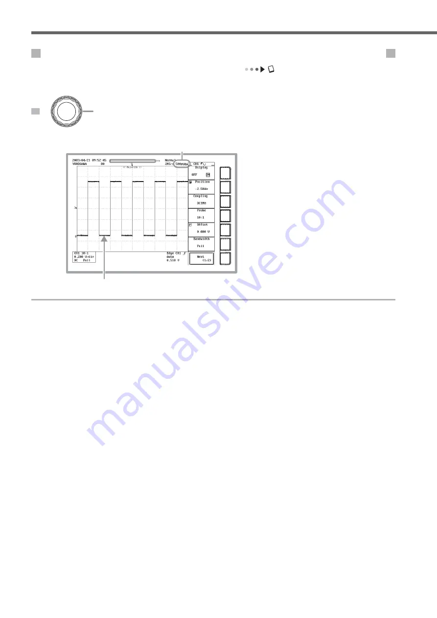
Changing the Time Axis Setting from 100 ms/div to 500 

µ

s/div

User’s manual section 5.12, “Setting T/div”

The display reverts from roll mode back to update mode, and five periods worth of the waveform is displayed.

1

Turn the TIME/DIV knob clockwise to set the time axis setting to 500 

µ

s/div.

Time axis setting on CH1

Update mode display

TIME/DIV

Working with the DL7400

Summary of Contents for DL7440

Page 1: ...DL7440 DL7480 Digital Oscilloscope IM 701450 02E 2nd Edition...

Page 2: ...y questions or find any errors please contact your nearest YOKOGAWA representative as listed on the back cover of this manual Copying or reproducing all or any part of the contents of this manual with...

Page 3: ...y and Jog Shuttle Operation 10 Introduction to Main Functions 12 Working with the DL7400 17 Preparing for an Observation 17 Displaying a Waveform on the Screen 19 Changing Waveform Display Conditions...

Page 4: ...ns Waveform Display Conditions Installing the Instrument Connecting the Power Supply and Turning ON OFF the Power Switch Connecting the Probe Initializing the Settings Performing Auto Setup Vertical A...

Page 5: ...the current axis sensitivity is set when setting the current to voltage conversion ratio PRESET key Section 5 7 Displays a menu for automatically setting the probe attenuation current to voltage conv...

Page 6: ...he record length acquisition mode interleave mode sampling rate and time base during waveform acquisition START STOP key Section 7 1 Starts stops waveform acquisition according to the trigger mode The...

Page 7: ...ess backlight self test and remote control It can also be used to display settings and the system status options installed on the unit firmware version etc SNAP SHOT key Section 8 6 Displays a non upd...

Page 8: ...e from the trigger position Label of the displayed waveform Section 8 9 Scale value Section 8 8 Comment The comment specified when printing or saving the screen image is displayed Trigger type Section...

Page 9: ...lay frame Z2 display frame Record length for the Z1 display T div for Z2 T div for Z1 Record length for the main normal waveform display Record length for the Z2 display Screen When Displaying Logic W...

Page 10: ...en Screen When Displaying X Y Waveforms User s manual section 8 5 Displaying X Y Waveform Main normal waveform display area X Y waveform display frame X axis scale Y axis scale Waveform assigned to X...

Page 11: ...isplay the corresponding menu Note Selecting an item among displayed selections Each time you press the soft key the selection item changes The selected item is highlighted Selecting Items by displayi...

Page 12: ...USB PERIPHERAL connector on the rear panel of the instrument you can use the mouse to perform the same operations available with the front panel keys Top menu Right click in the display waveform displ...

Page 13: ...ference time OR trigger A trigger activates when at least one of the trigger conditions from several trigger sources is met Window trigger A trigger activates when a trigger source enters or exits a w...

Page 14: ...tal axis and the signal level of another waveform assigned to the Y axis waveform for which display is ON and displays the relationship between the two You can observe an X Y waveform and the normal T...

Page 15: ...me The zoom position automatically moves in the specified direction You can watch the zoomed waveform as it scrolls then stop it at any desired position Auto scroll Analyzing or Searching SPI Signals...

Page 16: ...eters The following five results of statistical processing are performed on the same two measured items from automatic measurement of waveform parameters Max Min Avg Sdv Cnt count or the number of max...

Page 17: ...een images Snapshot waveform Displayed in white Updated waveform Ethernet Communications User s manual chapter 13 Ethernet Communications Optional You can transmit data or control the DL7400 using the...

Page 18: ...onnecting the power supply you must read the warnings in the user s manual listed in section 3 3 Connecting the Power Supply and Turning ON OFF the Power Switch 3 prong outlet Power cord accessory Pow...

Page 19: ...e Probe Phase Correction Phase adjustment hole Functional ground terminal Probe compensation signal output terminal Probe For instructions on how to connect a logic probe see section 3 6 When actually...

Page 20: ...rocedure are the following The date time setting communication settings stored settings the language setting and the SCSI ID setting To initialize all settings but the date time setting perform the pr...

Page 21: ...default number of screen divisions is four Quad In this case we only want to observe channel 1 so we change the setting to Single 1 screen DISPLAY 2Open the selection menu then choose Single 1Press th...

Page 22: ...ime Axis Setting from 200 s div to 100 ms div User s manual section 5 12 Setting T div The time axis setting is the setting for the amount of time per grid division If you slow increase the value of t...

Page 23: ...l section 5 12 Setting T div The display reverts from roll mode back to update mode and five periods worth of the waveform is displayed 1Turn the TIME DIV knob clockwise to set the time axis setting t...

Page 24: ...gger mode determines the conditions such as timing and the number of times at which the waveform display is updated If you execute auto setup the trigger mode is set to auto mode Five trigger modes ar...

Page 25: ...nding soft key Trigger position mark Pre trigger portion Post trigger portion Trigger point 2Turn the jog shuttle counterclockwise to set Position to 30 0 The waveform shifts 2 div to the left Changin...

Page 26: ...form Working with the DL7400 Measuring a Waveform This section explains how to use the vertical cursors to measure the voltage and period of the displayed waveform In addition to cursor measurement th...

Page 27: ...or Z1 5Set Z2 Mag in the same manner If you activate the jog shuttle on both Z1 Mag and Z2 Mag you can set both zoom factors at the same time Zoom box Z2 Zoom box Z1 Main normal waveform display area...

Page 28: ...ettings using this menu are not required by this operation guide but it may be useful to know that you can specify the print destination built in printer USB printer or network printer the printing fo...

Page 29: ...ng Drive name of the storage medium See previous page These settings not required by this operation guide but you can enter them as needed 2Choose Waveform waveform data 3Display the Save menu 4Displa...

Reviews: