


LIST OF SELF-DIAGNOSTIC AND FAIL-SAFE ACTIONS
9-6
*
1: Symbols used in the explanations of the malfunction history
: Normal
: There is currently a malfunction or abnormal condition.
: A malfunction or abnormal condition occurred previously, but the affected system or component
is currently operating normally.
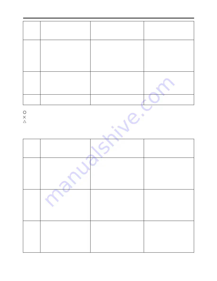
ACTUATOR OPERATION TABLE
64
Setting history display
• There is no history.
• There is some history.
• History is unknown (Histo-
ry data is damaged).
Displays the presence or ab-
sence of the setting history by
Power Tuner.
• 00
• 01
• 02
—
65
Setting map erasure
• There is no setting.
• There is some setting.
Displays the presence or ab-
sence of the setting history by
Power Tuner.
• 00
• 01
Erase all setting maps by
the operation start process-
ing.
70
Program version number
Displays a program version
No.
—
Diag-
nostic
code
No.
Item
Actuation
Procedure
30
Ignition coil
Actuates the ignition coil five
times at one-second inter-
vals.
“WARNING” on the Yamaha
diagnostic tool blinks five
times when the ignition coil is
actuated.
Check that a spark is gener-
ated five times.
• Connect an ignition
checker.
36
Injector
Actuates the injector five
times at one-second inter-
vals.
“WARNING” on the Yamaha
diagnostic tool blinks five
times when the radiator fan
motor relay is actuated.
TIP: Before performing
this operation, be sure to
disconnect the fuel pump
coupler.
Check that injector is actu-
ated five times by listening
for the operating sound.
51
Radiator fan motor relay
Actuates the radiator fan mo-
tor relay five times at five-sec-
ond intervals.
“WARNING” on the Yamaha
diagnostic tool blinks five
times when the radiator fan
motor relay is actuated.
Check that the radiator fan
motor relay is actuated five
times by listening for the op-
erating sound.
Diag-
nostic
code
No.
Item
Display
Procedure
Summary of Contents for YZ 2015 Series
Page 6: ...EASB291006 YAMAHA MOTOR CORPORATION U S A YZ MOTORCYCLE LIMITED WARRANTY...
Page 10: ......
Page 33: ...CONTROL FUNCTIONS 1 21 a 2...
Page 65: ...LUBRICATION POINTS AND LUBRICANT TYPES 2 22 EASB291066...
Page 68: ...LUBRICATION SYSTEM CHART AND DIAGRAMS 2 25...
Page 70: ...LUBRICATION SYSTEM CHART AND DIAGRAMS 2 27...
Page 72: ...LUBRICATION SYSTEM CHART AND DIAGRAMS 2 29...
Page 74: ...CABLE ROUTING DIAGRAM 2 31 EASB291068 CABLE ROUTING DIAGRAM...
Page 76: ...CABLE ROUTING DIAGRAM 2 33...
Page 78: ...CABLE ROUTING DIAGRAM 2 35...
Page 80: ...CABLE ROUTING DIAGRAM 2 37...
Page 82: ...CABLE ROUTING DIAGRAM 2 39...
Page 84: ...CABLE ROUTING DIAGRAM 2 41...
Page 86: ...CABLE ROUTING DIAGRAM 2 43...
Page 88: ...CABLE ROUTING DIAGRAM 2 45...
Page 128: ...ELECTRICAL SYSTEM 3 38...
Page 200: ...CHAIN DRIVE 4 70...
Page 244: ...ELECTRIC STARTER 5 41...
Page 266: ...OIL PUMP AND BALANCER GEAR 5 63 c d 6 6 7 8 8 b...
Page 286: ...TRANSMISSION 5 83...
Page 306: ...CHECKING THE INTAKE AIR TEMPERATURE SENSOR 8 67 CHECKING THE FUEL INJECTOR 8 68...
Page 321: ...CHARGING SYSTEM 8 15 EASB291338...
Page 325: ...COOLING SYSTEM For JPN 8 19 EASB291341...
Page 355: ...FUEL PUMP SYSTEM 8 49 EASB291348...
Page 356: ...ELECTRICAL COMPONENTS 8 50 ELECTRICAL COMPONENTS EASB291349 8 9 10 1 3 2 4 5 6 7...
Page 358: ...ELECTRICAL COMPONENTS 8 52 11 10 9 2 3 1 6 7 8 4 5...
Page 360: ...ELECTRICAL COMPONENTS 8 54 EASB291350 CHECKING THE SWITCHES 4 1 3 2 E B S E B E B E E B B...
Page 382: ...LIST OF SELF DIAGNOSTIC AND FAIL SAFE ACTIONS 9 7...


