ENGINE
3-6
▲▲▲▲▲▲▲▲▲▲▲▲▲▲▲▲▲▲▲▲▲▲▲▲▲▲▲▲▲▲▲▲
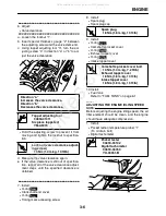
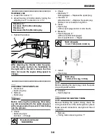
6. Adjust:
●
Valve clearance
▼▼▼▼▼▼▼▼▼▼▼▼▼▼▼▼▼▼▼▼▼▼▼▼▼▼▼▼▼▼▼▼
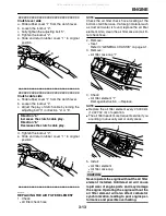
a. Loosen the locknut “1”
b. Insert special thickness gauge “2” between
the adjusting screw and the valve stem end.
c. Using tappet adjusting tool “3”, turn the ad-
justing screw “4” in direction “a” or “b” to ad-
just the valve clearance.
●
Hold the adjusting screw to prevent it from
moving and tighten the locknut to specifica-
tion.
d. Measure the valve clearance again.
e. If the valve clearance is still out of specifica-
tion, repeat all of the valve clearance adjust-
ment steps until the specified clearance is
obtained.
▲▲▲▲▲▲▲▲▲▲▲▲▲▲▲▲▲▲▲▲▲▲▲▲▲▲▲▲▲▲▲▲
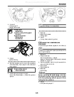
7. Install:
●
O-ring
●
Crankshaft end cover
●
O-ring
●
Timing mark accessing screw
8. Install:
●
Spark plug
●
Spark plug cap
9. Install:
●
O-ring
●
Camshaft sprocket cover
●
O-ring
●
Exhaust tappet cover
●
O-ring
●
Intake tappet cover
10.Install:
●
Fuel tank
Refer to “FUEL TANK” on page 6-1.
EAS20610
ADJUSTING THE ENGINE IDLING SPEED
NOTE:
Before adjusting the engine idling speed, the air
filter element should be clean, and the engine
should have adequate compression.
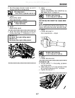
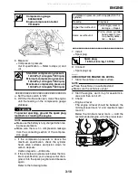
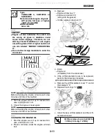
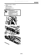
1. Install:
●
Pocket tester (temperature probe) “1”
(To oil drain bolt)
●
Digital tachometer
Direction “a”
Increases the valve clearance.
Direction “b”
Decreases the valve clearance.
Tappet adjusting tool
90890-01311
Six piece tappet set
YM-A5970
Lock nut (valve clearance adjust-
ing screw)
14 Nm (1.4 m•kg, 10 ft•lb)
1
4
3
2
a
b
T
R
.
.
New
New
Spark plug
18 Nm (1.8 m•kg, 13 ft•lb)
Camshaft sprocket cover bolt
10 Nm (1.0 m•kg, 7.2 ft•lb)
Exhaust tappet cover
18 Nm (1.8 m•kg, 13 ft•lb)
Intake tappet cover
18 Nm (1.8 m•kg, 13 ft•lb)
Pocket tester
90890-03132
Digital tachometer
90890-06760
YU-39951-B
T
R
.
.
New
New
New
T
R
.
.
1
All manuals and user guides at all-guides.com
all-guides.com
Summary of Contents for XT250X 2008
Page 2: ...All manuals and user guides at all guides com...
Page 8: ...All manuals and user guides at all guides com...
Page 54: ...CABLE ROUTING 2 35 All manuals and user guides at all guides com...
Page 82: ...ELECTRICAL SYSTEM 3 27 a b All manuals and user guides at all guides com...
Page 170: ...VALVES AND VALVE SPRINGS 5 24 All manuals and user guides at all guides com...
Page 224: ...AIR INDUCTION SYSTEM 6 13 All manuals and user guides at all guides com...
Page 239: ...CHARGING SYSTEM 7 14 All manuals and user guides at all guides com...
Page 243: ...LIGHTING SYSTEM 7 18 All manuals and user guides at all guides com...
Page 249: ...SIGNALING SYSTEM 7 24 All manuals and user guides at all guides com...
Page 253: ...CARBURETOR HEATING SYSTEM 7 28 All manuals and user guides at all guides com...
Page 279: ...All manuals and user guides at all guides com...

