CABLE ROUTING
2-26
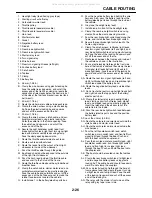
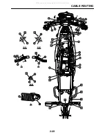
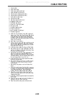
1. Headlight relay (lead having gray tape)
2. Starting circuit cut-off relay
3. Carburetor warmer lead
4. Throttle pulley
5. Throttle cable (decelerator cable )
6. Throttle cable (accelerator cable)
7. Horn lead
8. Starter motor lead
9. Diode1
10. Negative battery lead
11. Diode3
12. Rear brake light switch
13. Rear brake light switch lead
14. Starter relay lead
15. Turn signal relay
16. Wire harness
17. Rear turn signal light leads (left/right)
18. Positive battery lead
19. Clutch cable
20. Toolbox
21. Clamp
22. Battery box
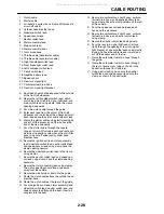
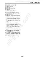
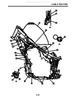
A. 35 mm (1.38 in)
B. Clamp the wire harness using plastic locking tie.
Face the cable tie end upwards, and cut off the
excess end of the tie. When clamping, locate the
connection of relay leads below the seat rails, but
at the side of the fuel tank bracket (rear fuel tank
bolt mount).
C. 30 mm (1.18 in)
D. Route the starter motor cable outside each lead.
E. Clamp the wire harness using a plastic locking
tie. Face the plastic locking tie end upwards,
and cut off the excess end of the tie.
F. 30 mm (1.18 in)
G. Clamp the wire harness, clutch cable, and car-
buretor warmer lead using plastic locking tie.
Enter the cable tie in the frame opening. Face
the cable tie end upwards, and cut off the
excess end of the tie.
H. Secure the right handlebar switch lead, front
brake light switch lead, right front turn signal light
lead, and meter assembly leads using clamp.
Face the clamp opening downwards.
I. Route the throttle cable inside of each lead.
J. Route each lead without slack.
K. Route the leads from the cutout of front right
sidecover to inside of the sidecover.
L. Pass the throttle cable through the guide.
M. Each lead should not be exposed to the outside
of the right front sidecover.
N. Pass the horn lead inside of the throttle cable
and secure it to the T-stud of the frame.
O. Route the throttle cable above the cylinder head
breather hose.
P. Clamp the clutch cable, starter motor lead, and
carburetor warmer lead using plastic locking tie.
Face the cable tie end outwards and cut off the
excess end of the tie. Take care not to make the
latchet face inwards towards the vehicle.
Q. Install diode 1 in the battery/electric parts box.
R. Pass the negative battery lead behind the wire
harness. Also, pass the battery lead from the
battery/electric parts box through the inside of
the vehicle.
S. Gray tape (headlight relay lead)
T. Install diode 3 in front of the headlight relay.
U. Clamp the rear brake light switch lead using
clamps. Face the clamp opening inwards .
V. Pass the rear brake light switch lead along the
frame, and install the rear brake light switch.
W. Secure the rear brake light switch lead to the
frame using clamps.
X. Clamp the wire harness, tail/brake light leads,
rear turn signal light leads (left and right), and
rear brake light switch lead using plastic locking
tie. Face the end of the locking tie upward and
cut off the excess end of the tie.
Y. Route leads between the frames and inside of
the vehicle as shown in the illustration.
Z. Pass a plastic locking tie through the front side
hole of the frame bracket and then clamp the rear
turn signal light leads (left and right) and tail/
brake light leads. Face the end of the locking tie
upward and cut off the excess end of the locking
tie.
AA. Route the rear turn signal light leads (left and
right), tail/brake light leads, and rear brake light
switch lead under the battery band.
AB. Route the negative battery lead outside other
leads.
AC. Do not route the rear turn signal light leads (left
and right) above the top panel of the battery/
electric parts box.
AD. Clamp the starter relay lead, headlight relay
lead, starting circuit cut-off relay lead, diode1
lead, and diode3 lead using plastic locking tie.
Insert the latchet and the excess tail of the
cable tie into the inside.
AE. Pass the rear brake light switch lead between
the battery/electric parts box and the positive
battery lead.
AF. Less than 2 mm (0.08 in)
AG. Route the carburetor warmer lead outside the
clutch cable and starter motor lead.
AH. Route the carburetor warmer lead outside the
wire harness.
AI. Pass the left handlebar switch lead, clutch
switch lead, main switch lead, and front left turn
signal light lead through the boot. Push and
hold the boot onto the coupler end.
AJ. Pass the horn lead, meter assembly lead, right
handlebar switch lead, front brake light switch
lead, and front right turn signal light lead
through the boot. Push and hold the boot onto
the coupler end.
AK. The boot should be located under the toolbox
end.
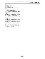
AL. Clamp the rear brake switch lead, taillight lead
and two negative battery leads using plastic
locking tie. The cable tie end should face down-
ward. Do not clamp the couplers.
AM. Pass a plastic locking tie through the hole of
frame gasset and then clamp the rear turn sig-
nal light leads and tail light lead. Face the end
of the locking tie upward and cut off the excess
end of the locking tie.
AN. The relay with the diode is front side and the
relay with gray tape is rear side.
All manuals and user guides at all-guides.com
Summary of Contents for XT250X 2008
Page 2: ...All manuals and user guides at all guides com...
Page 8: ...All manuals and user guides at all guides com...
Page 54: ...CABLE ROUTING 2 35 All manuals and user guides at all guides com...
Page 82: ...ELECTRICAL SYSTEM 3 27 a b All manuals and user guides at all guides com...
Page 170: ...VALVES AND VALVE SPRINGS 5 24 All manuals and user guides at all guides com...
Page 224: ...AIR INDUCTION SYSTEM 6 13 All manuals and user guides at all guides com...
Page 239: ...CHARGING SYSTEM 7 14 All manuals and user guides at all guides com...
Page 243: ...LIGHTING SYSTEM 7 18 All manuals and user guides at all guides com...
Page 249: ...SIGNALING SYSTEM 7 24 All manuals and user guides at all guides com...
Page 253: ...CARBURETOR HEATING SYSTEM 7 28 All manuals and user guides at all guides com...
Page 279: ...All manuals and user guides at all guides com...

