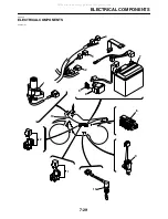


ELECTRICAL COMPONENTS
7-36
EAS27990
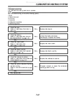
CHECKING THE BULBS AND BULB
SOCKETS
Check each bulb and bulb socket for damage or
wear, proper connections, and also for continu-
ity between the terminals.
Damage/wear
→
Repair or replace the bulb,
bulb socket or both.
Improperly connected
→
Properly connect.
No continuity
→
Repair or replace the bulb, bulb
socket or both.
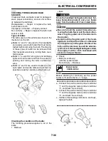
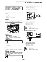
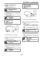
Types of bulbs
The bulbs used on this vehicle are shown in the
illustration on the left.
●
Bulbs “a” and “b” are used for the headlights
and usually use a bulb holder that must be de-
tached before removing the bulb. The majority
of these types of bulbs can be removed from
their respective socket by turning them coun-
terclockwise.
●
Bulbs “c” is used for turn signal and tail/brake
lights and can be removed from the socket by
pushing and turning the bulb counterclock-
wise.
●
Bulbs “d” and “e” are used for meter and indi-
cator lights and can be removed from their re-
spective socket by carefully pulling them out.
Checking the condition of the bulbs
The following procedure applies to all of the
bulbs.
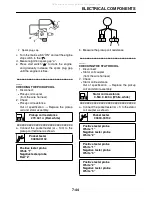
1. Remove:
●
Bulb
WARNING
EWA13320
Since the headlight bulb gets extremely hot,
keep flammable products and your hands
away from the bulb until it has cooled down.
CAUTION:
ECA14380
●
Be sure to hold the socket firmly when re-
moving the bulb. Never pull the lead, other-
wise it may be pulled out of the terminal in
the coupler.
●
Avoid touching the glass part of the head-
light bulb to keep it free from oil, otherwise
the transparency of the glass, the life of the
bulb, and the luminous flux will be adverse-
ly affected. If the headlight bulb gets soiled,
thoroughly it with a cloth moistened with
alcohol or lacquer thinner.
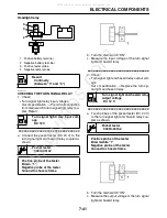
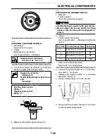
2. Check:
●
Bulb (for continuity)
(with the pocket tester)
No continuity
→
Replace.
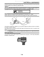
NOTE:
Before checking for continuity, set the pocket
tester to “0” and to the “
Ω ×
1” range.
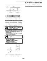
▼▼▼▼▼▼▼▼▼▼▼▼▼▼▼▼▼▼▼▼▼▼▼▼▼▼▼▼▼▼▼▼
a. Connect the positive tester probe to terminal
“1” and the negative tester probe to terminal
“2”, and check the continuity.
b. Connect the positive tester probe to terminal
“1” and the negative tester probe to terminal
“3”, and check the continuity.
c. If either of the readings indicate no continuity,
replace the bulb.
▲▲▲▲▲▲▲▲▲▲▲▲▲▲▲▲▲▲▲▲▲▲▲▲▲▲▲▲▲▲▲▲
Pocket tester
90890-03132
All manuals and user guides at all-guides.com
all-guides.com
Summary of Contents for XT250X 2008
Page 2: ...All manuals and user guides at all guides com...
Page 8: ...All manuals and user guides at all guides com...
Page 54: ...CABLE ROUTING 2 35 All manuals and user guides at all guides com...
Page 82: ...ELECTRICAL SYSTEM 3 27 a b All manuals and user guides at all guides com...
Page 170: ...VALVES AND VALVE SPRINGS 5 24 All manuals and user guides at all guides com...
Page 224: ...AIR INDUCTION SYSTEM 6 13 All manuals and user guides at all guides com...
Page 239: ...CHARGING SYSTEM 7 14 All manuals and user guides at all guides com...
Page 243: ...LIGHTING SYSTEM 7 18 All manuals and user guides at all guides com...
Page 249: ...SIGNALING SYSTEM 7 24 All manuals and user guides at all guides com...
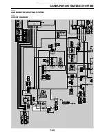
Page 253: ...CARBURETOR HEATING SYSTEM 7 28 All manuals and user guides at all guides com...
Page 279: ...All manuals and user guides at all guides com...