3-3
Periodic service
Periodic service
Fuel line check
1.
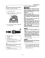
Remove the service lid.
2.
Check the fuel hoses and hose connec-
tions for fuel leakage.
3.
Check the fuel hoses. Replace if cracked
or damaged.
4.
Check the fuel hose routing and the
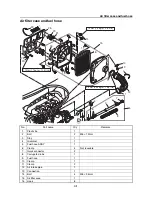
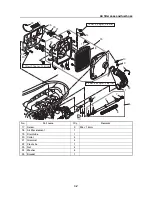
clamps. See “Air filter case and fuel hose”
(4-1) and “Fuel tank and fuel pump mod-
ule” (4-9).
5.
Supply power to the ECM and check that
the fuel pump module functions.
6.
Check the fuel hoses and hose connec-
tions for fuel leakage.
7.
Install the service lid.
Fuel filler cap and water separator
check
1.
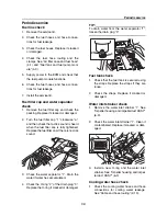
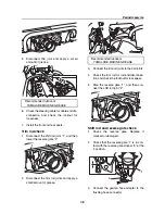
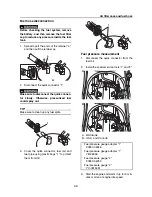
Remove the fuel filler cap and check the
packing. Replace if cracked or damaged.
2.
Turn the fuel filler cap “1” clockwise “a”,
and then check that a click sound is heard
when the fuel filler cap is fully tightened.
Replace the fuel filler cap if there is no click
sound.
3.
Check the water separator “1”. Drain the
water if water has accumulated.
4.
Check the O-ring “2” of the drain plug “3”.
Replace the O-ring if cracked or damaged.
TIP:
To drain water from the water separator “1”,
loosen the drain plug “3”.
Fuel tank check
1.
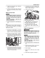
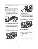
Check that the fuel tank is secured using
the straps. Replace the straps if they are
loose.
2.
Check the straps. Replace if cracked or
damaged.
Water inlet strainer check
1.
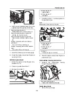
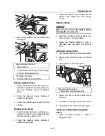
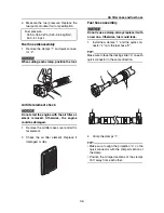
Remove the water inlet strainer “1”. See
“Impeller housing and impeller duct ASSY”
(6-9).
2.
Check the water inlet strainer “1”. Clean if
contaminated. Replace if cracked or dam-
aged.
3.
Install a new O-ring and the water inlet
strainer. See “Impeller housing and impel-
ler duct ASSY” (6-9).
Cooling water hose check
1.
Check the cooling water hoses and hose
connections for cooling water leakage.
See “Cable and hose routing” (2-13).
1
a
2
3
1
1
1
Summary of Contents for Waverunner VXS VX1800
Page 1: ...SERVICE MANUAL WaveRunner VXS VX1800 F2W VXR VX1800A F2W F2W 28197 ZU 11 ...
Page 12: ...How to use this manual 1 7 UP Upside YDIS Yamaha Diagnostic System Abbreviation Description ...
Page 40: ...Technical tips 1 35 MEMO ...
Page 163: ...Oil separator tank and oil pan 5 72 3 4 4 4 4 4 9 4 1 5 6 10 11 7 2 3 8 ...
Page 180: ...Crankcase connecting rod and piston 5 89 MEMO ...
Page 204: ...6 23 Intermediate housing Intermediate housing bolt 2 17 Nm 1 7 kgf m 12 5 ft lb 1 2 3 ...
Page 205: ...Intermediate housing 6 24 MEMO ...
Page 251: ...Indication system 7 44 MEMO ...
Page 278: ...8 25 Exhaust system 6 Install the band Rubber hose clamp 2 3 5 Nm 0 35 kgf m 2 58 ft lb ...
Page 290: ...Deck and hull 8 37 MEMO ...
Page 312: ...Engine unit troubleshooting 9 21 MEMO ...
Page 313: ...A Appendix Wiring diagram A 1 How to use the wiring diagram A 1 VXS VXR A 2 ...
Page 317: ......
Page 318: ...Mar 2015 CR E ...

