5-85
Crankcase, connecting rod, and piston
5.
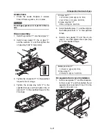
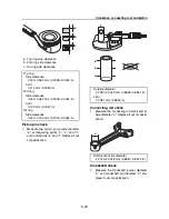
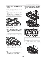
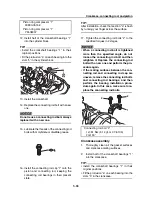
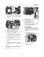
Install the upper bearing into the connect-
ing rod “2” and lower bearing into the con-
necting rod cap “3”.
TIP:
• Install the connecting rod bearings “1” in their
original positions.
• Fit the protrusion “a” on each bearing into the
slots “b” in the connecting rod cap “3” and
connecting rod “2”.
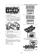
6.
Clean the connecting rod bolts.
7.
Lubricate the threads of the connecting rod
bolts with molybdenum disulfide grease.
8.
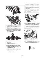
Before installing the connecting rod onto
the crankshaft, assemble the connecting
rod to which the connecting rod bearings
have been installed in step 5 to the crank-
shaft, keeping the present state.
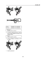
TIP:
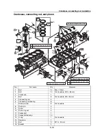
Tighten the connecting rod bolts while check-
ing that the sections shown “a” and “b” are
flush with each other by touching the surface.
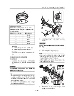
9.
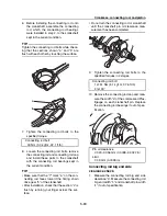
Tighten the connecting rod bolts to the
specified torque.
10. Loosen the connecting rod bolts, and then
remove the connecting rod and connecting
rod cap, keeping the connecting rod bear-
ings in the present state.
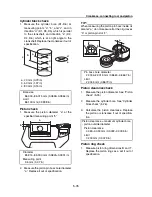
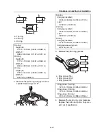
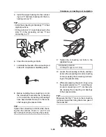
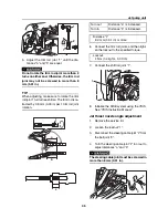
11. While compressing the piston rings using
the special service tool “1”, install the pis-
ton and connecting rod “2” into the cylin-
der, keeping the connecting rod bearings
in their present state.
TIP:
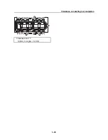
Make sure that the “Y” mark on the connecting
rod faces toward the timing chain drive gear of
the crankshaft.
b
a
3
2
1
b
Connecting rod bolt
30 Nm (3.0 kgf·m, 22.1 ft·lb)
a
b
2
1
Y
Summary of Contents for Waverunner VXS VX1800
Page 1: ...SERVICE MANUAL WaveRunner VXS VX1800 F2W VXR VX1800A F2W F2W 28197 ZU 11 ...
Page 12: ...How to use this manual 1 7 UP Upside YDIS Yamaha Diagnostic System Abbreviation Description ...
Page 40: ...Technical tips 1 35 MEMO ...
Page 163: ...Oil separator tank and oil pan 5 72 3 4 4 4 4 4 9 4 1 5 6 10 11 7 2 3 8 ...
Page 180: ...Crankcase connecting rod and piston 5 89 MEMO ...
Page 204: ...6 23 Intermediate housing Intermediate housing bolt 2 17 Nm 1 7 kgf m 12 5 ft lb 1 2 3 ...
Page 205: ...Intermediate housing 6 24 MEMO ...
Page 251: ...Indication system 7 44 MEMO ...
Page 278: ...8 25 Exhaust system 6 Install the band Rubber hose clamp 2 3 5 Nm 0 35 kgf m 2 58 ft lb ...
Page 290: ...Deck and hull 8 37 MEMO ...
Page 312: ...Engine unit troubleshooting 9 21 MEMO ...
Page 313: ...A Appendix Wiring diagram A 1 How to use the wiring diagram A 1 VXS VXR A 2 ...
Page 317: ......
Page 318: ...Mar 2015 CR E ...

