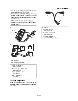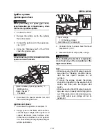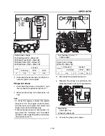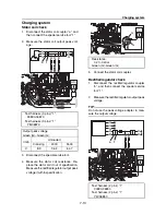
7
Electrical system
Fuel system ...................................................................... 7-29
Fuel injector check ................................................................... 7-29
Fuel pump relay check ............................................................. 7-29
Fuel pump module check ......................................................... 7-30
Starting system ................................................................ 7-31
Fuse check ............................................................................... 7-31
Handlebar switch (left) check ................................................... 7-31
Main relay check ...................................................................... 7-31
Starter relay check ................................................................... 7-32
Starter motor .................................................................... 7-34
Starter motor operation ............................................................ 7-35
Armature check ........................................................................ 7-35
Brush holder check................................................................... 7-36
Remote control system ................................................... 7-37
Remote control transmitter check............................................. 7-37
Remote control receiver check................................................. 7-38
Transmitter registration ............................................................ 7-38
Indication system ............................................................. 7-40
Multifunction meter check......................................................... 7-40
Speed sensor check................................................................. 7-40
Fuel level meter display
and fuel level warning indicator check...................................... 7-41
Check engine warning indicator check..................................... 7-41
Diagnostic display check .......................................................... 7-42
Oil pressure warning indicator check ....................................... 7-42
Engine overheat warning indicator check................................. 7-42
Buzzer check............................................................................ 7-43
Summary of Contents for Waverunner VXS VX1800
Page 1: ...SERVICE MANUAL WaveRunner VXS VX1800 F2W VXR VX1800A F2W F2W 28197 ZU 11 ...
Page 12: ...How to use this manual 1 7 UP Upside YDIS Yamaha Diagnostic System Abbreviation Description ...
Page 40: ...Technical tips 1 35 MEMO ...
Page 163: ...Oil separator tank and oil pan 5 72 3 4 4 4 4 4 9 4 1 5 6 10 11 7 2 3 8 ...
Page 180: ...Crankcase connecting rod and piston 5 89 MEMO ...
Page 204: ...6 23 Intermediate housing Intermediate housing bolt 2 17 Nm 1 7 kgf m 12 5 ft lb 1 2 3 ...
Page 205: ...Intermediate housing 6 24 MEMO ...
Page 251: ...Indication system 7 44 MEMO ...
Page 278: ...8 25 Exhaust system 6 Install the band Rubber hose clamp 2 3 5 Nm 0 35 kgf m 2 58 ft lb ...
Page 290: ...Deck and hull 8 37 MEMO ...
Page 312: ...Engine unit troubleshooting 9 21 MEMO ...
Page 313: ...A Appendix Wiring diagram A 1 How to use the wiring diagram A 1 VXS VXR A 2 ...
Page 317: ......
Page 318: ...Mar 2015 CR E ...

