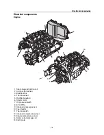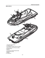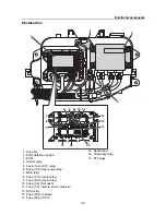
Electrical components
7-4
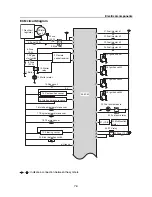
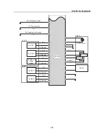
ECM circuit diagram
,
: Indicate a connection between the symbols.
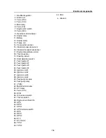
Stator
coil
F
u
se
(20 A)
Main relay
8
.F
u
se
(30 A)
7.Engine
start s
w
itch
10.Starter
relay
12.Starter motor
Pick
u
p coil
Cam position sensor
15.Intake air press
u
re sensor
16.Intake air temperat
u
re sensor
17.Engine temperat
u
re sensor
1
8
.Thermo sensor
Steering sensor
Slant detection s
w
itch
F
u
el injector #1
F
u
el injector #2
F
u
el injector #3
F
u
el injector #4
Ignition coil #1
Ignition coil #2
Ignition coil #3
Ignition coil #4
F
u
el p
u
mp mod
u
le
(YDIS)
32.M
u
ltif
u
nction
meter
ETV relay
F
u
se (10 A)
35.ECM
Rectifier /
reg
u
lator
1.
2.
3.
5.
11.Battery
13.
14.
19.
20.
21.
22.
23.
24.
25.
26.
27.
2
8
.
29.
30.F
u
el p
u
mp relay
31.
33.
34.
F
u
se
(3 A)
9.Remote
control recei
v
er
F
u
se (10 A)
4.
6.
5 V
a.Gro
u
nd
7
r
s
µ
¥
º
u
t
©
g
®
]
e
Q
J
K
D
\
8
P
3
F
E
M
C
O
G
5
^
Summary of Contents for Waverunner VXS VX1800
Page 1: ...SERVICE MANUAL WaveRunner VXS VX1800 F2W VXR VX1800A F2W F2W 28197 ZU 11 ...
Page 12: ...How to use this manual 1 7 UP Upside YDIS Yamaha Diagnostic System Abbreviation Description ...
Page 40: ...Technical tips 1 35 MEMO ...
Page 163: ...Oil separator tank and oil pan 5 72 3 4 4 4 4 4 9 4 1 5 6 10 11 7 2 3 8 ...
Page 180: ...Crankcase connecting rod and piston 5 89 MEMO ...
Page 204: ...6 23 Intermediate housing Intermediate housing bolt 2 17 Nm 1 7 kgf m 12 5 ft lb 1 2 3 ...
Page 205: ...Intermediate housing 6 24 MEMO ...
Page 251: ...Indication system 7 44 MEMO ...
Page 278: ...8 25 Exhaust system 6 Install the band Rubber hose clamp 2 3 5 Nm 0 35 kgf m 2 58 ft lb ...
Page 290: ...Deck and hull 8 37 MEMO ...
Page 312: ...Engine unit troubleshooting 9 21 MEMO ...
Page 313: ...A Appendix Wiring diagram A 1 How to use the wiring diagram A 1 VXS VXR A 2 ...
Page 317: ......
Page 318: ...Mar 2015 CR E ...

