7-35
Starter motor
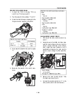
Starter motor operation
1.
Remove the starter motor. See “Wire har-
ness” (5-18).
2.
Hold the starter motor in a vise using alu-
minum plates on both sides.
3.
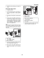
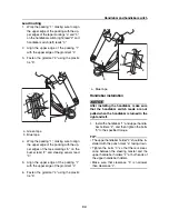
Connect the positive battery lead “1” to the
starter motor terminal bolt “a”.
4.
Connect the negative battery lead “2” to
the starter motor body “b”, and then check
the starter motor operation.
Do not touch the drive gear.
TIP:
• Check the starter motor operation for a few
seconds.
• If the starter motor is disassembled, make
sure to check the operation again after as-
sembling it.
5.
Disconnect the negative battery lead, and
then the positive battery lead from the bat-
tery terminals.
6.
Install the starter motor. See “Wire har-
ness” (5-18).
Armature check
1.
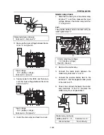
Check the commutator. Clean using 600-
grit sandpaper and compressed air if dirty.
2.
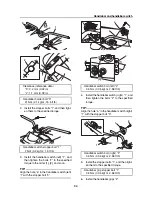
Measure the commutator diameter “a”.
Replace the armature if below specifica-
tion.
3.
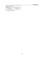
Measure the commutator undercut “a”.
Replace the armature if below specifica-
tion.
4.
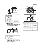
Check the armature for continuity. Re-
place if out of specification.
a
1
2
b
Commutator diameter
28.0 mm (1.10 in)
Limit
27.0 mm (1.06 in)
Commutator undercut
0.7 mm (0.03 in)
a
a
Summary of Contents for Waverunner VXS VX1800
Page 1: ...SERVICE MANUAL WaveRunner VXS VX1800 F2W VXR VX1800A F2W F2W 28197 ZU 11 ...
Page 12: ...How to use this manual 1 7 UP Upside YDIS Yamaha Diagnostic System Abbreviation Description ...
Page 40: ...Technical tips 1 35 MEMO ...
Page 163: ...Oil separator tank and oil pan 5 72 3 4 4 4 4 4 9 4 1 5 6 10 11 7 2 3 8 ...
Page 180: ...Crankcase connecting rod and piston 5 89 MEMO ...
Page 204: ...6 23 Intermediate housing Intermediate housing bolt 2 17 Nm 1 7 kgf m 12 5 ft lb 1 2 3 ...
Page 205: ...Intermediate housing 6 24 MEMO ...
Page 251: ...Indication system 7 44 MEMO ...
Page 278: ...8 25 Exhaust system 6 Install the band Rubber hose clamp 2 3 5 Nm 0 35 kgf m 2 58 ft lb ...
Page 290: ...Deck and hull 8 37 MEMO ...
Page 312: ...Engine unit troubleshooting 9 21 MEMO ...
Page 313: ...A Appendix Wiring diagram A 1 How to use the wiring diagram A 1 VXS VXR A 2 ...
Page 317: ......
Page 318: ...Mar 2015 CR E ...


