For Service Engineer
Service Information
SI1705004E-00=SIGMA-G5SII Service Manual
210/273
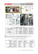
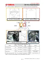
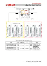
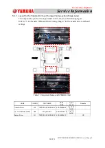
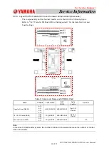
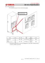
5.3.8. Layout for the Transfer Unit over the lower frame section (Dual Lane)
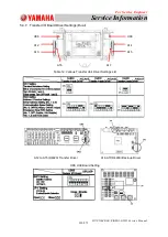
The component layout for the dual transfer unit is shown in the following figure.
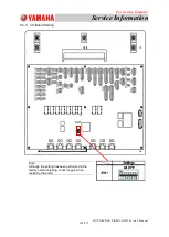
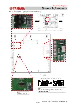
Refer to "5.4.7 Transfer I/O Board Driver Settings (dual)" for the transfer driver and
board settings.
Table 8: Component Name and SYMBOL Chart
Note:
In the case of dual transfer system, the number of drivers is increased because the number of control
axes is increased.
NAME
SYMBOL
PART NAME
PART
CODE
Fig.No
Key.No
Remarks
Transfer Driver (D4920)
A12
A13
A14
A15
UNIT_DRIVER
KYB-M913W-00
Fig H1-12
No.B42
16 - 16 I/O Board (UB95)
U08
U09
PCB_MOUNT
KYB-M91AK-00
Fig C1-3
No.B41
Backup Driver (D4460)
A16
A17
PCB_MOUNT
KYB-M91DE-00
OP
A10
U08
FRONT
REAR


