For Service Engineer
Service Information
SI1705004E-00=SIGMA-G5SII Service Manual
158/273
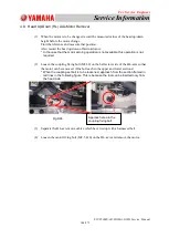
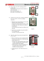
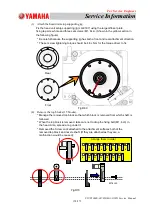
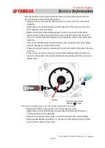
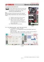
(3) Attach the head unit setup supporting jig.
Fix the head unit setup supporting jig (JG-0197) using the large diffuser plate
fixing tap screw hole and three set screws (M1. 6L4). (Shown in the yellow section in
the following figure)
* Be careful because the supporting jig has both a front and rear attachment direction.
* The set screw tightening torque should be 4.8 cN
m for the torque driver to fix.
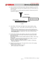
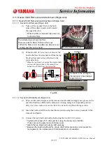
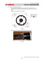
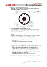
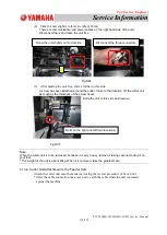
(4) Remove the top blocks (15 blocks).
* Manage the removed top block so that which block is removed from which shaft, is
followed.
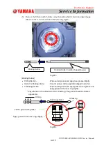
* When the top block is removed, take care not to drop the fixing bolt (M1. 6L3) in
the head. Also, spread a rag under it.
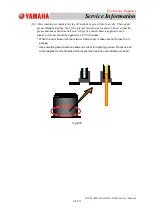
* Removed the Screw Lock attached to the attachment surfaces both of the
removed top block and nozzle shaft. (If they are attached as they are, a
malfunction would be caused).
Rear
Front
Fig.D69
Fig.D70
M1.6×L3
Arrange them in order
1 2 3 4 5 6 7 8
9 10 11 12 13 14 15

