For Service Engineer
Service Information
SI1705004E-00=SIGMA-G5SII Service Manual
197/273
4.21.1.4. Checks
(1)
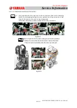
Attach HV82C and HA09C to any nozzle in the head to be adjusted.
(2)
Insert the cart in the machine and turn ON the power to the machine.
(3)
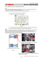
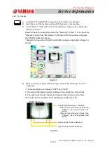
Select
"
Maint.
"
,
"
Unit Adj.
"
, and
"
Linear Measure
"
in this order to display the
following window.
Select the head to be adjusted and set the
"
Base line
"
to
"
Exist
"
. Then, press the
"
Operation
"
key for the
"
Dtct.Nozzle
"
in the lower left of the window, and press
the [START] button to measure.
* Measure it using each of HV82C and HA09C nozzles as described in Steps (4)
and (5).
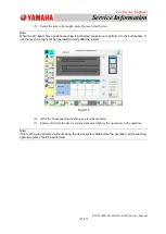
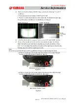
(4) Make sure that the obtained HV81C image satisfies the following
"
i
"
to
"
iii
"
conditions.
ⅰ
. The measured value is between
"
0.385
"
and
"
0.616
"
.
ⅱ
. The outline of the light projector is between the external two vertical lines.
ⅲ
. The right and left ends of nozzle are between the inner two vertical lines.
If any of the above conditions is not satisfied, go to Step (7) or (8).
HV82C OK Image
Fig.D125
Fig.D126
Nozzle Height Reference = 0.500mm
・
When the measured value is smaller than
“0.500mm”, the nozzle tip end is over
the line.
・
When the measured value is larger than
“0.500mm”, the nozzle tip end is under
the line.
Nozzle Lateral Position Reference
Light Projector Outline Reference

