134
Chapter 13. Graphic EQ
The PM1D system provides twenty-four 31-band graphic EQ modules. This chapter explains how to operate the graphic
EQ.
Inserting a graphic EQ into a channel
The 24 GEQ (graphic EQ) modules built into the PM1D system can be patched to the insert-out/insert-in of a desired
channel. Here we will explain how to insert a graphic EQ into an input channel.
[Procedure]
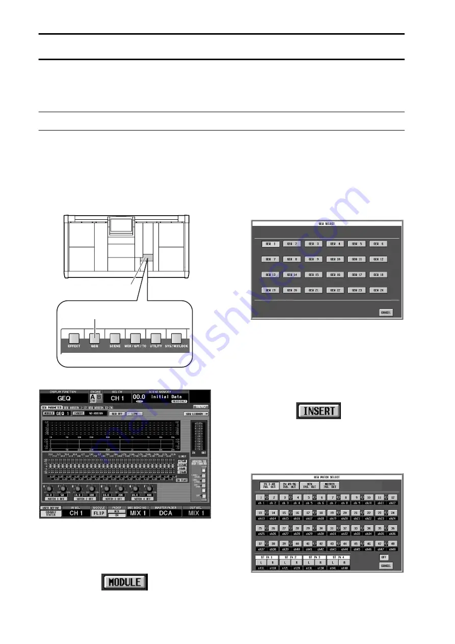
1. In the LCD FUNCTION ACCESS block, press the
[GEQ] switch several times to access the following
GEQ PARAMETER screen.
•
GEQ PARAMETER screen (GEQ function)
In the GEQ PARAMETER screen you can select a
specific GEQ module, select the patch destination
channel, and set the parameters.
2. Click the MODULE button in the upper left of the
screen.
A GEQ SELECT popup window will appear, allowing
you to select a GEQ module (1–24).
•
GEQ SELECT popup window
3. Select the desired module from GEQ 1 – GEQ 24,
and click the corresponding button.
When you click a button, you will return to the GEQ
PARAMETER screen. Notice that the selected mod-
ule is displayed at the right of the MODULE button.
4. Click the INSERT button located at the right of the
MODULE button.
The GEQ PATCH SELECT popup window will
appear, allowing you to select the patch destination
for the GEQ module.
•
GEQ PATCH SELECT popup window
In this window, you will first use the top row of but-
tons to select the type of channel, and then use the
remaining buttons to select the channel number.
LCD FUNCTION ACCESS
block
[GEQ] switch
Summary of Contents for CS1D
Page 14: ...Owner s Manual ...
Page 18: ...Operating Manual ...
Page 19: ...Operating Manual Start up ...
Page 68: ...Operating Manual Basic Operation ...
Page 227: ...Reference Manual ...
Page 228: ...Reference Manual Hardware ...
Page 345: ...Reference Manual Software ...
Page 543: ...Reference Manual Appendices ...


