background image

43

Pla y  Ef fe cts

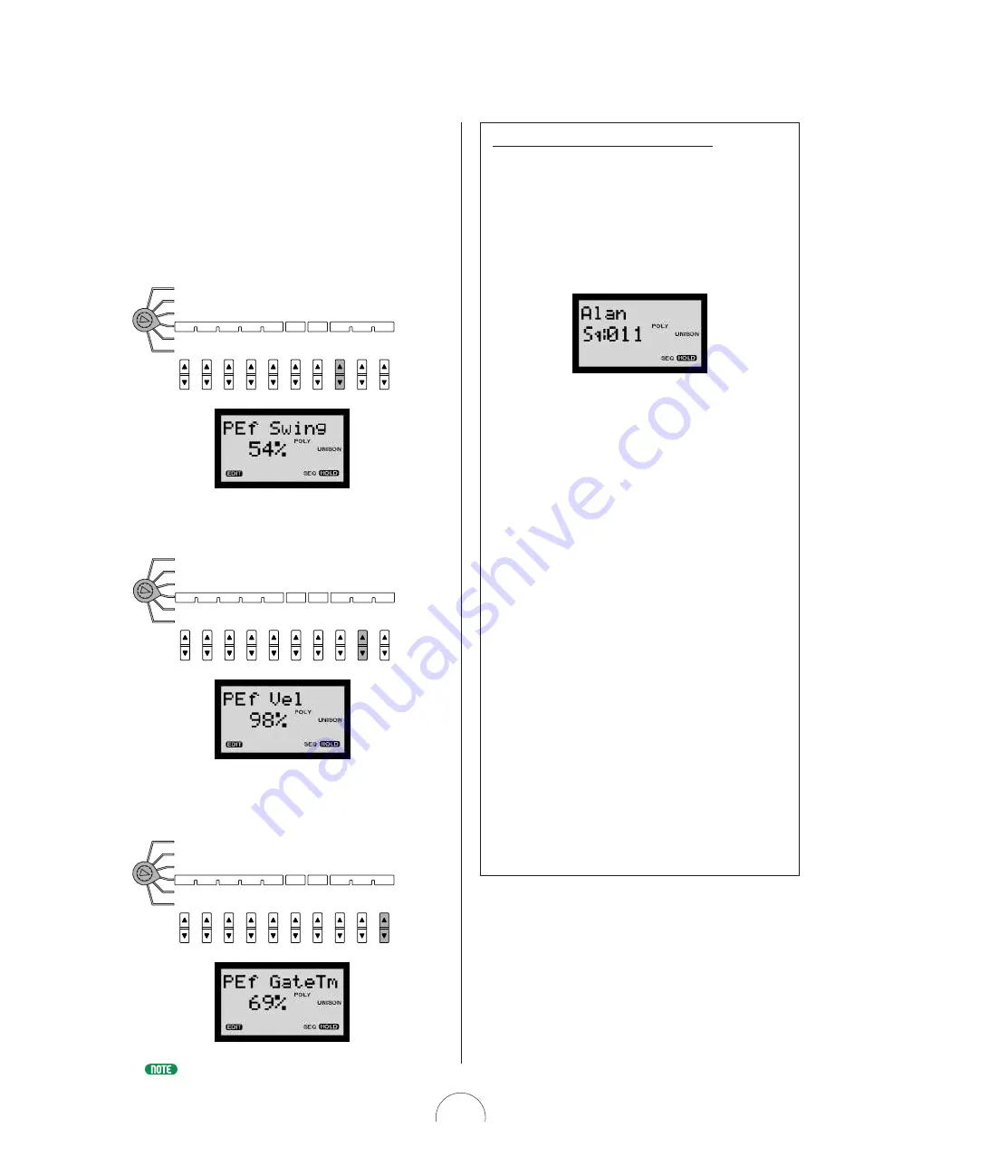
The Play Effect (“ Play EF” ) parameters let yo u desig nate

setting s which can permit the Step Sequencer pattern to

o btain a mo re human “ feel” . (O r even a less o ne, if

that’s what yo u’ re g o ing  fo r!) There are three Play

Effect parameters, Swing , Velo city and G ate Time.

Sw ing:

Lets yo u create a “ swing ”  feel by slig htly

shifting  certain beats.

Velocity :

Lets yo u set the ratio  between lo wer and

hig her velo city values o f each step.

Ga te Tim e:

Lets yo u adjust the no te leng th (the

duratio n o f the no te) either sho rter o r lo ng er, as a

percentag e o f the o rig inal. 

For more information about Play Effects and available settings, see page 8 8 .

Common
Arp / SEQ

Type/No

VOICE
ARPEGGIO / SEQ

KbdMode

Hold

SceneSw

MIDI
Ptn Tx Ch

Arpeggio

Subdivide

Play EF
Swing

Velocity

GateTime

Common
Arp / SEQ

Type/No

VOICE
ARPEGGIO / SEQ

KbdMode

Hold

SceneSw

MIDI
Ptn Tx Ch

Arpeggio

Subdivide

Play EF
Swing

Velocity

GateTime

Common
Arp / SEQ

Type/No

VOICE
ARPEGGIO / SEQ

KbdMode

Hold

SceneSw

MIDI
Ptn Tx Ch

Arpeggio

Subdivide

Play EF
Swing

Velocity

GateTime

Ex ploring The Fa ctory -set Pa tterns

To  help g et a clearer understanding  o f ho w the vario us Step
Sequencer-related parameters and setting s wo rk, yo u may
want to  take so me time and systematically examine the
details o f so me o f the facto ry-set vo ices which are specially
pro g rammed to  demo nstrate the po wer and rang e o f the Step
Sequencer, and chang e the vario us setting s to  analyz e the
po ssible effects.

As an example, use the PRO G RAM CHAN G E keypad to
select “ Sq:0 1 1  Alan” , then trig g er the pattern. 

This vo ice uses the Ho ld functio n, so  the pattern will play
repeatedly as yo u check the vario us setting s, as fo llo ws:

1 . N otice w hich La y er m ode a ppea rs in the LCD.

Check  KbdM ode a nd Scene Sw itch settings, a s
w ell a s Pla y  Effect settings in the V O ICE
ARPEGGIO / SEQ  m enu.

2 . Check  the Split Point in the V O ICE CO M M O N

m enu.

3 . Set the [EDIT RO TARY] sw itch to the SEQ

EDIT/ SETUP m enu a nd check  the Ba se Unit,
Length a nd Loop Ty pe settings.

4 . Repea t the ba sic process a bove for ea ch voice

w hich uses the Step Sequencer. 

W hile yo u’ re at it, why no t g o  ahead and step thro ug h so me
o f the facto ry-set Vo ice and User Pattern while the sequence
is lo o ping ?  Press (Pattern) Bank [UP/ DO W N ] to  select the
Vo ice o r User Pattern bank, then press (Pattern) N o
[UP/ DO W N ] to  select and listen to  each pattern.

And do n’ t be shy abo ut playing  aro und with the different
parameter setting s and see what effect they have o n the
sequence. If yo u stumble upo n so mething  that so unds g o o d
alo ng  the way, yo u mig ht want to  g o  ahead and sto re the
edited vo ice to  ano ther vo ice lo catio n befo re yo u lo se it! If
thing s g et to o  far o ut o f hand, simply reselect the same vo ice
with the PRO G RAM CHAN G E keypad and start o ver! It
wo n’ t take to o  lo ng  to  g et a clear understanding  o f ho w the
different setting s wo rk to g ether to  let yo u create and play
yo ur o wn ho t sequences.

Summary of Contents for AN1x

Page 1: ......

Page 2: ...2 ...

Page 3: ...117 PRECAUTION S 4 INTRODUCTION How To Use This Manual 5 Main Features 5 The AN 1x At A Glance 6 The Making Of A Modern Classic 8 W hat Is A Voice 9 AN 1x Memory Structure 9 ANALOG PHYSICAL M ODELING SYNTHESIS AN 1x Tone Generator 10 GETTING STARTED System Ex amples 12 Switching O n The Power 13 Playing The Demo Songs 13 Basic Operation 14 AN1x O perating Modes 14 Selecting Voices 14 Using The Con...

Page 4: ...onents turn off the power for all components Before turning the power on or off for all components set all volume levels to minimum Do not expose the instrument to excessive dust or vibrations or extreme cold or heat such as in direct sunlight near a heater or in a car during the day to prevent the possibility of panel disfiguration or damage to the internal components Do not use the instrument ne...

Page 5: ...assignable including PITCH and MODULATION wheels and various foot pedals plus the RIBBON controller with horizontal slide X and pressure Z control of filter LFO delay and more The Control Matrix function permits easy assignment of up to 16 sets of source controllers MW FC Key Touch etc to destination parameters VCA Filter LFO etc for each Scene all of which can be stored as voice data for each voi...

Page 6: ...d lower bend ranges for each Scene MODULATION w heel The assignable MODULATION wheel lets you apply modulation or another designated controllable parameter as you play or morph between Scenes when the Scene Control function is active and the MODULATION wheel is designated as the source controller CON TROL knobs w ith push sw itch knob parameters The eight assignable CONTROL knobs are used for real...

Page 7: ...nthesis block diagram provides a handy visual reference or reminder of how the signal flows through the key blocks or components of the AN1x s tone generation architecture which is helpful when manipulating the various parameters during voice editing or real time sound control Parameter value UP DOW N sw itches These ten switches are used to access and edit specific parameters as printed on the pa...

Page 8: ... a quarter of a century ago Enter the Yamaha AN1x Control Synthesizer a modern classic in its own right complete with the VCO VCF and VCA blocks or modules that give retro synths that famously fat rich warm sound plus multiple knobs for controlling every nuance of the sound and even an on board Arpeggiator and Step Sequencer for generating pattern loops at the press of a key W hat s much more howe...

Page 9: ...ther settings ARPEGGIO SEQ switch status and the various Arpeggiator and Step Sequencer parameter settings including Play Effect settings plus Step Sequencer Voice Pattern data System Data System data is made up of the various global parameter settings which remain in effect regardless of which voice is selected as follows UTIL ITY SETUP parameters including the settings for System tuning and keyb...

Page 10: ... volume The oscillator creates the source pitch The filter determines the timbre 1 VCO The VCO module is where the original sound waveform gets generated Although a single oscillator is enough to generate the basic sawtooth pulse square or other waves required for different types of musical instrument sounds the AN1x s VCO module is much more complex First there s a VCO 1 which includes an additio...

Page 11: ...re Delay and Reverb effects can be configured in a serial or parallel connection and specified effects or all effects excluding the EQ can be bypassed at will Controllers can be designated to control specific effect parameters For more information see as follow s Vari EF EQ page 77 Dly Rev EF page 79 EF Bypass page 80 5 CONTROL Specific parameters of the VCO MIX VCF VCF VCA and EFFECT modules as w...

Page 12: ...lest level all you need to do is connect stereo headphones to the PHO NES jack located on the rear panel and you re ready to go T o use the AN1x as a stand alone performance instrument simply connect it to amplified speakers and optional FC Foot Controller and Footswitch pedals as shown in the diagram at right Setting Up Your AN1x The AN1x Control Synthesizer is an ideal stand alone performance ba...

Page 13: ...OLUME knob to the right w hile playing the keyboard until you achieve a comfortable listening level VOLUME MDR SEO JOB UTIL MIDI MIDI DATA FILTER CURSOR FILE DATA REC PAUSE START STOP TEMPO MDF2 etc AN1x MIDI IN MIDI OUT MIDI IN MIDI OUT Playing The Demo Songs The AN 1x comes preprogrammed w ith demonstration songs w hich provide dynamic ex amples of just how pow erful the AN 1x really is To selec...

Page 14: ...ting to know the AN 1x to be fun and inspiring especially if you keep a few fundamental things in mind as you select and play the voices try out the various controls and ex periment w ith the panel features for the first time Follow ing are some important aspects about basic operation of the AN 1x w hich w ill help you keep things in their proper contex t from the very start AN1 x Operating M odes...

Page 15: ...ch Src Edge Port Time Edge Release Release Noise Level PW HPF Feedback VCF PWM Depth PWM Src PWM Src PWM Depth Type Reso nance Volume FEG Depth Fmod Depth Amod Depth Vel Sens Key Track Vel Sens Algorithm Wave Attack Attack ASSIGN 1 ASSIGN 2 ASSIGN 3 ASSIGN 4 PEG Decay Wave VCO1 Fine Fine PEG Sw FM Src2 LFO2 Spd PmodDepth PmodDepth Level LFO1 Wave LFO1 Spd LFO1 Dly PW ASSIGN 5 ASSIGN 6 ASSIGN 7 ASS...

Page 16: ...h to the 5th position SEQ EDIT SETUP menu the CO NTRO Lknobs will be dedicated to the event parameters of the various steps beats of the Step Sequencer In this situation no L ED will be lit in the KNO B PARAMETER GRO UP section and the name of the current step event parameters will appear in the L CD when you turn or press a knob Simply pressing a KNO B PARAMETER GRO UP switch will revert the stat...

Page 17: ...ad to select a voice 1 128 For information about selecting voices see Basic Operation page 14 2 Check LCD status W hen you select a voice first take a look at the information which appears in the L CD such as Poly mode PO L Y MO NO L EGATO L ayer mode SINGL E UNISO N DUAL SPL IT etc and whether the Arpeggiator ARP or Sequencer SEQ is on This reveals the fundamental nature of a voice at a glance Th...

Page 18: ...ou play the keyboard If the voice does not use the Arpeggiator or Step Sequencer press ARPEGGIO SEQ to turn on the Arpeggiator or Step Sequencer and hear how notes and chords are affected For more information about the Arpeggiator see page 33 For information about the Step Sequencer see page 37 8 Change arpeggio Tempo Pattern Type Subdivision and Hold status T o speed up or slow down the Arpeggiat...

Page 19: ... sounds to choose from at any time within each of the 128 voices at the simple press of a SCENE switch Scenes are especially handy for creating slight variations on the same sound for use during different parts of a song say one with fast attack that cuts through the mix during rhythmic phrases and one with a slower attack that s more suitable for a pad And of course if the two Scenes are complete...

Page 20: ...rs see page 95 The procedure for activating the Scene Control function is as follows 1 Press both SCEN E sw itches simultaneously The LEDs to the left of both sw itches w ill light to indicate that Scene Control is active 2 Roll the MODULATION w heel forw ard and back or use a Foot Controller etc as you play The minimum value of the MO DUL ATIO N wheel or Foot Controller etc plays Scene 1 the maxi...

Page 21: ... In SPL IT mode the Scene Control will morph from the Scene 1 sound to the Scene 2 sound when the keyboard is played to the left of the Split Point only W hen the keyboard is played to the right of the Split Point only the Scene 2 sound will be played For more information about Layer modes see page 22 Layer mode SPLIT Scene Control Edit Buffer SPLIT POINT Scene 1 Scene 2 Layer mode DUAL Scene Cont...

Page 22: ...GIO SEQ Common SceneSw parameter CTRL SCENE STORE Selecting Layer M odes The LAYER sw itch is used for selecting a Layer mode from the six available Every time you press the sw itch a different Layer mode is selected The selected Layer at the time of a Voice Store operation is saved as voice data Each L ayer mode determines how Note O n messages from either the AN1x s keyboard or external MIDI dev...

Page 23: ...ch 1 Scene 2 range MIDI ch 2 Two incoming MIDI signals play each Scene independently across the entire keyboard according to Rx Ch settings SPLIT In this mode Scene 1 is assigned to the keys to the left of the variable Split Point see page 77 and Scene 2 is assigned to the keys to the right In SPL IT mode the AN1x is capable of multitimbral play max 2 sounds SPLIT UNISON In this mode each Scene on...

Page 24: ...tone generator portamento data is also output from the MIDI O UT terminal which means it can affect a voice of an external tone generator assigned to the same MIDI channel as the AN1x or be recorded as Control Change data in an external MIDI sequencer Turning PORTAM ENTO On And Off Pressing the PO RT AMENTO switch turns the portamento on or off Portamento on off status is stored as voice data Pres...

Page 25: ...tically by editing the various parameters Simply press a sw itch to access a group of parameters The selected sw itch w ill be indicated by a lit LED to the left of it The name of each parameter in the group is printed on the panel next to the knob by which it is edited color coded and arranged in relation to each KNO B PARAMETER GRO UP switch A description of each parameter group along with avail...

Page 26: ...th FM Src1 Sync Pitch Depth Sustain Ring Mod Sustain Sync Pitch Src Edge Port Time Edge Release Release Noise Level PW HPF Feedback VCF PWM Depth PWM Src PWM Src PWM Depth Type Reso nance Volume FEG Depth Fmod Depth Amod Depth Vel Sens Key Track Vel Sens If the EDIT RO T ARY switch is set to positions 1 4 or position 6 when you select a voice the ASSIGN switch will automatically be selected the L ...

Page 27: ... details on how to assign Control function parameters to the CONTROL knobs see page 95 For details on how to assign Control Matrix parameters to the CONTROL knobs see page 73 For a list of available parameters which can be assigned to each CONTROL knob see the separate Data List book Step Sequencer Event Edit If you set the EDIT RO T ARY switch to the SEQ EDIT SETUP menu position 5 or if you selec...

Page 28: ...mmon to both Scenes and Variation Effect Dry Wet balance parameter which can be set for each Scene VOICE FREE EG Includes Trigger and L ength setting Track and Parameter select plus recording and other parameters related to the Free EG function VOICE ARPEGGIO SEQ Includes common and specific parameters related to the Arpeggiator and Step Sequencer For a description of each parameter and available ...

Page 29: ...mory location 1 128 using the Voice Store operation see page 98 Parameters which you can edit at any time but which are not stored as voice data include system related parameters accessible from the UTILITY SETUP menu as well as Effect Bypass status VOICE COMMON menu and MIDI Pattern Transmit Channel VOICE ARPEGGIO SEQ menu As such they will remain as set regardless of which voice is selected Mode...

Page 30: ...each menu and available parameters see page 72 1 VCO Edit Pressing the VCO 1 KNO B PARAMETER GRO UP switch gives you access to the main voltage controlled oscillator parameters which let you select the basic waveform and determine the fundamental pitch of the sound Pressing the VCO 2 switch gives you access to the second oscillator which contains the same set of parameters as VCO 1 and lets you ad...

Page 31: ...RO Lknob 1 lets you adjust the PEG Decay or time required for the sound to reach its basic pitch from the PEG Depth setting CO NTRO Lknob 3 lets you set the PEG Switch to determine which VCO the PEG is applied to For more information about PEG Depth PEG Decay and PEG Switch parameters see page 55 VCO VCO1 SYNC MASTER SLAVE FM VCO2 2 VCF Edit Pressing the VCF KNO B PARAMETER GRO UP switch gives you...

Page 32: ...tremolo effect by using L FO 1 CO NTRO Lknob 8 lets you set the Velocity Sensitivity to determine the amplitude of the VCA in relation to playing strength to either increase dynamic range with a heavier or lighter touch For more information about Amod Depth and Vel Sens parameters see page 70 Feedba ck And Volume CO NTRO Lknob 5 lets you determine the feedback level which is output from the VCA an...

Page 33: ...tings Play Effect Velocity parameter and number of notes played you have a w ide range of control and customization over length rhythm and feel of a voice s arpeggio You can control which Scene plays the arpeggiated patterns turn the Arpeggio Hold function on and off at will and even designate an independent MIDI channel on which to output the Arpeggiator pattern data The specific Arpeggiator rela...

Page 34: ...nsable for tweaking the tone generator parameters for your arpeggios with the CO NTRO Lknobs Common Arp SEQ Type No VOICE ARPEGGIO SEQ KbdMode Hold SceneSw MIDI Ptn Tx Ch Arpeggio Subdivide Play EF Swing Velocity GateTime Arpeggio Pattern Types The 30 arpeggio pattern T ypes are selected by pressing T ype No UP DO W N The available T ypes are basically divided into two groups separated chords T yp...

Page 35: ...ce with L ayer mode and Keyboard Mode settings Common Arp SEQ Type No VOICE ARPEGGIO SEQ KbdMode Hold SceneSw MIDI Ptn Tx Ch Arpeggio Subdivide Play EF Swing Velocity GateTime Common Arp SEQ Type No VOICE ARPEGGIO SEQ KbdMode Hold SceneSw MIDI Ptn Tx Ch Arpeggio Subdivide Play EF Swing Velocity GateTime scne1 or scne2 W hen the Scene Switch is set to scne1 or scne2 Scene 1 or Scene 2 will play as ...

Page 36: ...ngth The length of an AN1x arpeggio pattern is determined by three factors which work together simultaneously Arpeggio T ype Arpeggio Subdivide setting and the total number of notes you play for an arpeggiated chord For example say you play an arpeggiated pattern with a four note chord such as a C major triad with an octave in the root If Subdivide is set to 1 8 the Arpeggiator breaks down the cho...

Page 37: ...er The Step Sequencer lets you create your ow n 16 step looped patterns by setting N ote Velocity Gate Time and Control Change event values for each step beat in the sequence using the CON TROL knobs w here each knob gives you access to the events in a specific step w hen the EDIT ROTARY sw itch is set to the SEQ EDIT SETUP menu Each of the 128 voices has its own Voice Pattern memory for storing a...

Page 38: ...Time Step Sequencer Hold M odes Pressing Hold UP DO W N lets you turn the SEQ Hold function on and off Depending on Keyboard Mode setting there are two additional Hold modes W hen SEQ Hold is set to on HO L D will appear in reverse type in the lower right corner of the L CD After triggering the Step Sequencer by playing the keyboard the sequence will continue playing automatically when you release...

Page 39: ...W N to select a pattern number that pattern will load into the Voice Pattern edit buffer Voice Patterns 128 Voice Pattern Edit Buffer Pattern loaded into the Voice Pattern edit buffer will be played Voice Bank User Patterns 128 User Bank SINGLE PATTERN PLAY All editing of the pattern will of course be taking place in the buffer If you want you can use SEQ Store UP DO W N to store the edited patter...

Page 40: ...ample if you assign Usr003 to C 1 then pressing C 1 selects User Pattern 003 pressing D1 selects Pattern 004 pressing D 1 selects Pattern 005 and so on T o assign a User Pattern number to C 1 set the EDIT RO T ARY switch to VO ICE ARPEGGIO SEQ and press T ype No UP DO W N Arp SEQ must be set to Step SEQ and KbdMode must be set to sel norm or sel shift See page 85 Playing Step Sequencer Patterns Th...

Page 41: ...a very high setting above C6 for example you can select a different pattern from any key SPLIT POINT Base pitch Shifts pattern Normal play Triggers current Voice Pattern sel shift Select Shift Playing a key to the left of the Split Point will trigger select a specific User Pattern based on C 1 Assign setting C1 will trigger the Voice Pattern for the current voice and playing keys to the right of t...

Page 42: ...nob Event 1 8 9 16 SEQ EDIT SETUP Step Hold Pattern Bank No Base Unit Length LoopType Ctrl No SEQ Store Knob Event 1 8 9 16 SEQ EDIT SETUP Step Hold Pattern Bank No Base Unit Length LoopType Ctrl No SEQ Store For more information about Loop Type see page 91 Scene Sw itch The Scene Switch setting in the VO ICE ARPEGGIO SEQ menu determines whether the Step Sequencer Pattern will play Scene 1 Scene 2...

Page 43: ...he power and range of the Step Sequencer and change the various settings to analyze the possible effects As an example use the PRO GRAM CHANGE keypad to select Sq 011 Alan then trigger the pattern This voice uses the Hold function so the pattern will play repeatedly as you check the various settings as follows 1 N otice w hich Layer mode appears in the LCD Check KbdMode and Scene Sw itch settings ...

Page 44: ...r value setting in the L CD T urning a knob will edit the value Event parameter name Select with Knob Event parameter Step number Depends on selected knob and Knob 1 8 9 16 setting Event parameter value Turn the knob to edit Knob Event 1 8 9 16 SEQ EDIT SETUP Step Hold Pattern Bank No Base Unit Length LoopType Ctrl No SEQ Store Knob Event Parameters T o designate which type of event to edit by the...

Page 45: ...nce Each time you press a different CO NTRO Lknob s push switch while Step Hold is active that step will be played and its information will appear in the L CD T urning a CO NTRO Lknob will edit the current event value of the selected step Knob Event 1 8 9 16 SEQ EDIT SETUP Step Hold Pattern Bank No Base Unit Length LoopType Ctrl No SEQ Store W hile Step Hold is active you can press Event UP DO W N...

Page 46: ...16 SEQ EDIT SETUP Step Hold Pattern Bank No Base Unit Length LoopType Ctrl No SEQ Store Step Sequencer M IDI Output You can use the MIDI Pattern Transmit Channel PtnTxCh parameter to designate a MIDI channel on which to output the Step Sequencer pattern data to either play an external tone generator or record the data into a MIDI sequencer or computer This setting is independent from the MIDI Tran...

Page 47: ...ons Following is a brief description of parameters available in each category Tra ck Common Pa ra meters Trigger Determines how the track playback is triggered either by pressing a key on the AN1x s keyboard after selecting a voice free a Note O n message from the keyboard or an external MIDI device kbd or by a Note O n message from either the keyboard an external device the Arpeggiator or Step Se...

Page 48: ...nce either to play once but not loop off to loop forward from beginning to end fwd to loop forward from middle to end half to Alternate i e loop from beginning to end then end to beginning alt or to Half Alternate i e loop from middle to end then end to middle half For more information see page 82 Length Determines the time for recording and play of the Free EG sequence either by number of measure...

Page 49: ... the sound of both the AN 1x itself as w ell as any connected MIDI instruments Real time Control The AN1x s real time controllers include all on board sound control features manipulated by hand or foot which also can output continuous Control Change data via MIDI including the eight CO NTRO Lknobs the MO DUL ATIO N wheel the PITCH wheel the RIBBO N controller with both horizontal X axis and Z axis...

Page 50: ...in the Control Assign function as well as in the Control Matrix you can use a single controller to control one parameter of the internal tone generator and another parameter of an external MIDI device both at the same time It also lets you determine which device MW FC etc to use for Scene Control see page 20 Controllers w hich can be assigned using the UTILITY SETUP Control function MW Modulation ...

Page 51: ...tch Bend Pitch Up and Down each Scene the number of the Set 1 16 for each Scene and Common 1 and 2 both Scenes parameter assignments Parameter Determines which parameter is assigned to the Scene Set Number 1 16 or Pitch Bend or Common Set 1 2 Mode Poly Port VOICE SCENE SETUP LFO Rst Ctrl Matrix Set No Param Source Depth Layer Pan Separate Unison Detune Source Determines which controller by Control...

Page 52: ... page 37 ABC 0 VWX MNO 7 YZ 8 PQR 5 GHI 2 4 DEF 1 OTHERS STU 9 6 JKL 3 YES ENTER NO Voice Category Voice name Poly mode Layer mode and Arp SEQ status Voice number ABC 0 VWX MNO 7 YZ 8 PQR 5 GHI 2 4 DEF 1 OTHERS STU 9 6 JKL 3 YES ENTER NO Procedure 2 1 Press to increment through the voices sequentially 2 Press to decrement through the voices sequentially In this case you do not need to press YES EN...

Page 53: ...PEG LFO SYNC FM VCO1 VCO2 MIX VCF VCF VCA ASSIGN Algorithm Wave Attack Attack ASSIGN 1 ASSIGN 2 ASSIGN 3 ASSIGN 4 PEG Decay Wave VCO1 Fine Fine PEG Sw FM Src2 LFO2 Spd PmodDepth PmodDepth KNOB PARAMETER GROUP PEG LFO SYNC FM VCO1 VCO2 MIX VCF VCF VCA ASSIGN 2 Press a CON TROL knob w ithout turning it The parameter name current value and a horizontal knob data graph will display in the L CD A flash...

Page 54: ... details see page 96 Indicates a voice has been edited but not stored Knob Parameters This section provides a description of each parameter available for control or edit in each KN OB PARAMETER GROUP KNOB PARAMETER GROUP ASSIGN 1 ASSIGN 2 ASSIGN 3 ASSIGN 4 ASSIGN 5 ASSIGN 6 ASSIGN 7 ASSIGN 8 PEG LFO PEG Decay PEG Depth PEG Sw Port Time LFO1 Wave LFO1 Spd LFO1 Dly LFO2 Spd SYNC FM Algorithm Sync Pi...

Page 55: ...determines the pitch in semitones W hen PEG Decay see above is set to a positive value the PEG Depth setting represents the start pitch W hen PEG Decay is set to a negative value the PEG Depth setting represents the end pitch T urning the knob to the left lowers the pitch while turning it to the right raises the pitch W hen the knob is set to center position basic pitch the pitch will not change S...

Page 56: ...ngs 0 127 For more information about Portamento see page 24 When the Portamento is turned off by the PORTAMENTO switch will flash in the LCD to indicate that the portamento function is not available for confirmation LFO1 Wave The L FO 1 W ave setting determines the type of wave for L FO 1 The wave set here determines the characteristics of the modulation applied to the VCO vibrato VCF wah and VCA ...

Page 57: ...57 Triangle Triangle Triangle Triangle180 Triangle180 Tri Triangle Wave Saw down Saw down Saw up Saw up Saw Sawtooth Wave Square Square Square180 Squ Square Wave ...

Page 58: ...ngs 0 127 LFO2 Spd LFO2 Speed Description parameters and values for L FO 2 Speed are the same as for L FO 1 Speed above The LFO2 wave is fixed to triangle and cannot be changed SYNC FM W hen KNO B PARAMETER GRO UP switch SYNC FM is selected the eight CO NTRO Lknobs will access specific Sync function and Frequency Modulation related parameters Sync parameters are related to the synchronization stat...

Page 59: ...ied to both master and Slave oscillators only FM Sync is disabled VCO1 Master of VCO1 VCO2 LFO1 2 EG etc FM Sync Pitch The Sync Pitch setting determines the pitch of the slave oscillator in semitones available only when the Sync is on This lets you create a difference in pitch between master and slave oscillators and control the resulting harmonic interval W hen the knob is in the center position ...

Page 60: ... setting determines the amount of modulation created by FM Source 1 see next parameter T urning the knob to the right increases the Depth Settings 64 0 63 This is a different type of parameter than that used in the Yamaha DX series FM synthesizers Too deep of a setting will change the pitch of the voice Adjust the pitch using the VCO1 Pitch and Fine parameters see pages 61 62 FM Src1 FM Source 1 T...

Page 61: ...pitch to a maximum of a full octave pulse Square The pulse square wave is used to make woodwind clarinet type sounds Its spectrum is similar to a sawtooth wave but since every second even numbered harmonic is missing the waveform contains only odd numbered harmonics when Pulse W idth see page 62 is set to 64 PW below 64 saw 2 Saw tooth2 The spectrum of the saw2 wave is created by a sawtooth wave c...

Page 62: ...ulse W idth The PW setting determines the width of the VCO 1 pulse wave T urning the knob to the right produces more harmonics resulting in a fatter sound In general pulse width is used to control the pulse wave however the AN1x can use PW with other waves as well for a wider possible variety of sounds than usual W hen set to 64 the Pulse W idth is equally balanced generating only odd numbered har...

Page 63: ...tch Modulation adds a cyclical change to the pitch to create a vibrato effect T urning the knob to the right widens the range of the pitch change Negative value settings reverse the phase of the L FO 1 by 180 degrees Settings 127 127 VCO2 W hen KNO B PARAMETER GRO UP switch VCO 2 is selected the eight CO NTRO Lknobs will access specific Voltage Controlled O scillator 2 related parameters including...

Page 64: ...nes the attack time of the FEG which is the time it takes for the signal to reach its maximum cutoff frequency level after a key is pressed key on T urning the knob to the right produces a longer Attack time Settings 0 127 Decay The Decay setting determines the decay time of the FEG which is the time it takes for the signal to reach its sustain level from the maximum level while a key is held T ur...

Page 65: ...ng of 0 applies no resonance Settings 12 0 102 Cutoff frequency Frequency Level 102 64 12 0 Range passed Cutoff frequency Frequency Cutoff range VCF Type Low Pass Filter FEG Depth The FEG Depth setting determines the range of movement of the cutoff frequency T urning the knob to the right increases the FEG Depth Negative values reverse the shape of the envelope W hen not using the FEG set the valu...

Page 66: ...ncreases the VCO 2 L evel W hen using the VCO 1 only set this value to 0 Settings 0 127 Ring M od Ring Modulator Level The Ring Modulator setting controls the balance of the Ring Modulator level in relation to the VCO 1 VCO 2 Noise and VCA Feedback levels T urning the knob to the right increases the Ring Modulator level W hen not using the Ring Modulator set this value to 0 Settings 0 127 The Ring...

Page 67: ... point A cutoff curve of 24dB octave L PF24 18dB octave L PF18 and 12dB octave L PF12 can be selected Cutoff frequency Frequency Level Cutoff range 12dB oct 18dB oct 24dB oct Range passed Cutoff frequency Frequency Level Cutoff range BPF The Band Pass Filter passes only those frequencies in the specified range with a cutoff curve of 12dB octave HPF12 The High Pass Filter passes only those frequenc...

Page 68: ...itch VCA is selected the eight CO NTRO Lknobs will access specific Voltage Controlled Amplifier related parameters The VCA is an amplifier used to increase the gain of the input signal as received from the VCF which is then passed to the Effect block in the signal path Available parameters include level controls for feedback volume and keyboard velocity sensitivity as well as depth control for amp...

Page 69: ...The Feedback setting determines the level of feedback output from the VCA and fed back into the input of the mixer causing the signal to build up in amplitude according to the level you set T urning the knob to the right increases the Feedback level resulting in a fatter sound Settings 0 127 Feedback should be applied slowly and with caution Too much feedback can create extremely high frequencies ...

Page 70: ...ve values requires a lighter touch to increase amplitude A value setting of 0 maintains the same amplitude regardless of playing strength Settings 64 0 63 ASSIGN W hen KNO B PARAMETER GRO UP switch ASSIGN is selected each of the eight CO NTRO Lknobs can be used as an individual controller for specified Control Change parameters which can be freely assigned Assign 1 8 As MIDI controllers knob movem...

Page 71: ...rl No SEQ Store Ctrl Device Ctrl No Edit Procedure The procedure for editing a voice is outlined below 1 Select a voice using the PROGRAM CHAN GE keypad Enter the number of the voice you want followed by YES ENTER or select the voice by pressing 2 Select the edit menu Set the EDIT RO T ARY switch to the menu with the parameter that you want to edit 3 Select the parameter that you w ant to edit Pre...

Page 72: ...er in each of the six Edit menus along w ith a listing of available settings VOICE SCENE SETUP This menu includes Mode Control Matrix and L ayer parameters which can be set and stored as voice data Mode and Control Matrix parameters can be stored as Scene data for each voice A Scene memory is simply a snapshot of the parameters as set by the eight CONTROL knobs There are two Scene memories which y...

Page 73: ... The Portamento setting mode here is effective and can be heard when the panel PORTAMENTO switch is set to ON LFO Rst LFO Reset The L FO Reset mode setting determines the start point of the L FO 1 and L FO 2 cycle Settings off L FO 1 and L FO 2 do not reset but modulate continuously ky on Key On L FO 1 and L FO 2 reset every time a key is pressed Ctrl M atrix Control Matrix Control Matrix Ctrl Mat...

Page 74: ...ts Settings PB Pitch Selects the Pitch Bend Up parameter for setting the range over which the pitch bends up above a value of 64 when rolling the Pitch Bend wheel between center and maximum forward position for the selected Scene PB Pitch Selects the Pitch Bend Down parameter for setting the range over which the pitch bends down below a value of 64 when rolling the Pitch Bend wheel between center ...

Page 75: ...TER GRO UP ASSIGN is on Depending on selected Parameter the available Source for assignment may be different For details of available parameters see the table of Control Matrix parameters in the separate Data List book You cannot assign the same Source controller and Parameter to more than one set If you attempt to lower numbered sets will take priority and will appear in the LCD for higher number...

Page 76: ...ge 22 Pa n The Pan parameter sets the type of stereo panning or the way the sound moves between the left and right speakers Settings off W hen L ayer mode is set to SINGL E see page 22 Pan control does not function W hen set to DUAL DUALUNISO N SPL IT or SPL IT UNISO N you can change the pan width for Scene 1 and Scene 2 using the Separate function see below alt Alternate Causes the sound to alter...

Page 77: ...Param Data Vari EF Dry Wet Dly Rev EF Param Data EF Bypass Name Cursor Char Split Pnt Split Point The Split Point setting determines the note at which the keyboard divides into lower Scene 1 and upper Scene 2 zones for Split mode play SPL IT SPL IT UNISO N mode It also determines the division for the Arpeggiator or Step Sequencer depending on Keyboard Mode setting For information about Split modes...

Page 78: ... Effect see the separate Data List book Setting the Equalizer 1 Press Param UP DOW N to select an EQ parameter There are seven EQ parameters see the separate Data List book 2 Press Data UP DOW N to set the value of the selected parameter as desired 3 Repeat steps 1 and 2 above as many times as necessary to select other parameters and set their data values For more information about the EQ paramete...

Page 79: ...n about available parameters and value settings for Delay and Reverb effects see the separate Data L ist book Setting Delay and Reverb 1 Press the low er area of the Param UP DOW N sw itch to select the Connect parameter 2 Press Data UP DOW N to select serial seri or parallel para and set the configuration of the Delay and Reverb effects 3 Press Param UP DOW N again to select either the Delay DlyE...

Page 80: ... Rev Both Delay and Reverb effects will be bypassed AllEF The signal bypasses all effects in the Effect block including Variation Effect Delay and Reverb excluding EQ Effect Bypass Mark The Effect Bypass mark will appear in the L CD when the Effect Bypass is active Name Name parameters let you select a voice Category and up to ten characters to give a customized name to your edited voice There are...

Page 81: ...t lets you record up to four tracks one parameter per track of real time changes of CO NTRO L knob position data all knobs over a specified length of time either in measures or seconds The parameter changes associated with the recorded knob movements will automatically play back as recorded when you subsequently play the voice from the keyboard You can select time length in bars up to 8 measures o...

Page 82: ...OW N set the Scene Scene 1 Scene 2 or both Scenes w hich you w ant the Free EG to affect 4 If necessary repeat steps 1 through 3 above for selecting other tracks and assigning parameters to them You cannot assign the same parameter to more than one track If you attempt to do so the latest recorded track takes priority while other tracks will automatically be turned off for the Scene Switch Trigger...

Page 83: ... executed After recording a track the next highest numbered track will automatically be selected for recording Settings REC OFF Free EG is not recording REC STBY Trk Standby situation for the selected track The Free EG is ready to record based on the Trigger setting REC STBY All Standby situation for recording on all four tracks at the same time a different parameter for each The Free EG is ready ...

Page 84: ...ode or during recording you can stop the record operation by turning the EDIT ROTARY switch and return to the REC OFF status If you want to record in the selected track choose REC STBY Trk If you want to record in all four tracks choose REC STBY All 2 Change the Free EG Length see page 82 or select a Track Number for the selected Parameter see page 83 W hen the L ength parameter is set to bar the ...

Page 85: ...tep Sequencer see page 37 Common Common parameters are related to both the Arpeggiator and Step Sequencer There are five parameters available including Arp SEQ T ype No Number KbdMode Keyboard Mode Hold and SceneSw Scene Switch Common Arp SEQ Type No VOICE ARPEGGIO SEQ KbdMode Hold SceneSw MIDI Ptn Tx Ch Arpeggio Subdivide Play EF Swing Velocity GateTime Arp SEQ Arpeggiator Sequencer The Arp SEQ s...

Page 86: ...ay W hen Arp SEQ is set to Step Sequencer norm N ormal For triggering the Voice Pattern of the currently selected voice at its base pitch from any key on the keyboard and playing the voice normally across the keyboard If Hold is set to off then the pattern will start each time you press a key shift norm Shift N ormal Playing a key to the left of the Split Point will shift the pitch of the pattern ...

Page 87: ...d and KbdMode is set to norm or shift norm on off W hen Step Sequencer is selected and KbdMode is set to sel norm or sel shift off mode1 mode2 mode1 A pattern will be triggered every time a key is pressed mode2 A pattern will be triggered after the current sequence finishes even if you press a key during the middle of the current sequence Base pitch C4 Shifts low Shifts high SPLIT POINT Shifts Pat...

Page 88: ... 83 qqq 3 qqq 3 hhh 3 Velocity The Velocity parameter sets the ratio between the lower and higher velocity values of the Arpeggiator or Step Sequencer pattern over a range between 1 and 200 A setting of 100 maintains the original velocity relationship between the notes L ower values adjust velocities downward at playback and higher values adjust velocities upward at playback A setting of real Real...

Page 89: ...Control Number parameter in the same menu row see page 91 Knob Event 1 8 9 16 SEQ EDIT SETUP Step Hold Pattern Bank No Base Unit Length LoopType Ctrl No SEQ Store 1 8 9 1 6 This parameter lets you designate which series of steps 1 8 or 9 16 are available for data entry using the eight CO NTRO Lknobs Each knob as positioned on the panel 1 8 relates to the corresponding sequence step either 1 8 or 9...

Page 90: ...with the Bank parameter above You can select from 128 patterns in each bank For a list of patterns see the Sequence Pattern L ist in the separate Data L ist book Settings 1 128 Sequence Patterns and Banks W hen you select a voice which has the Common KbdMode parameter set to norm or shift norm Voice Pattern data for the voice is loaded Subsequently you can select a Voice Pattern bank or number or ...

Page 91: ...repeatedly e g 1 2 3 4 4 3 2 1 1 etc alternateB The pattern plays from first step to last forward then reverses starting from the next to last step then loops in this manner repeatedly e g 1 2 3 4 3 2 1 2 3 4 3 etc qqq 3 qqq 3 hhh 3 91 Ctrl No Control N umber The Control Number setting determines the type of MIDI Control Change which can be output upon sequencer play O nce the Control Number is se...

Page 92: ...ng pitch for the AN1x s tone generator in approx 0 3 cent values 100 cents 1 semitone Settings 100 0 100 System MstrTune Kbd Trans UTILITY SETUP Kbd Vel MIDI Tx Ch Rx Ch DeviceNo Local BulkDump Ctrl Device Ctrl No KbdTra ns Keyboard Transpose The Keyboard Transpose parameter determines the transposition setting for the keyboard in semitones Settings 36 0 basic pitch 36 Kbd Vel Keyboard Velocity Th...

Page 93: ...mp Tx Ch Transmit Channel The Transmit Channel parameter sets the MIDI channel on which the AN1x s keyboard controllers and switches transmit MIDI messages W hen not transmitting to an external device set Tx Ch to off Although MIDI Tx Ch and MIDI PtnTxCh can be set to the same channel the notes played on the keyboard may interfere with the notes of the Arpeggiator or Step Sequencer pattern Therefo...

Page 94: ... 1 64 65 128 ptn Sends data for the User Pattern bank 65 128 all ptn Sends all Step Sequencer User Pattern data system Sends all system parameter data all Sends all data in memory DeviceNo Device N umber The Device Number parameter lets you set the MIDI device number when performing bulk dump operations or when transmitting and receiving System Exclusive messages Both devices should be set to the ...

Page 95: ...c by assigning Control Change numbers to specific controllers devices There are two parameters available Device and Control Number Based on settings made here as well as in the Control Matrix see pages 51 73 you can use a single controller to control one parameter of the internal tone generator and another parameter of an external MIDI device both at the same time It also lets you determine which ...

Page 96: ... settings unique to the AN1x T o change between modes first turn off the power Then press and hold ASSIGN and press the PO W ER switch Either mode1 or mode2 will appear in the L CD at the start up procedure to indicate which mode is activated When using Mode 2 take care when making Control Change assignments since the behavior will be different from the MIDI standard For a list of Control Change t...

Page 97: ...ogrammed for specific types of voices as follows 1 Normal all settings normalized 2 Bass 3 Brass 4 Strings 5 E Piano 6 O rgan 7 Sync mono for solo lead type voices 8 PW M for pad type voices ABC 0 VWX MNO 7 YZ 8 PQR 5 GHI 2 4 DEF 1 OTHERS STU 9 6 JKL 3 YES ENTER NO ABC 0 VWX MNO 7 YZ 8 PQR 5 GHI 2 4 DEF 1 OTHERS STU 9 6 JKL 3 YES ENTER NO 4 Press YES EN TER to initialize the voice data The initial...

Page 98: ...number 1 128 using the PROGRAM CHAN GE keypad representing the location in w hich you w ant to store the edited voice follow ed by EN TER or select the location w ith The voice name flashes alternately w ith HIT STORE Step 2 can be omitted if you want to store the voice to the same location number In such a case go straight to step 3 3 Press the store sw itch again SURE Y N appears in the LCD If a...

Page 99: ... a Voice Store operation to store the Scene data as part of the voice along w ith Scene on off status Scene Select After selecting a voice press SCENE 1 or SCENE 2 to select the desired scene The L ED appears beside the selected switch to indicate the active Scene At least one Scene is active at all times Scene Control Press both SCENE switches to activate the Scene Control function which can be c...

Page 100: ...ory sets 1 1 64 voice loads voices 1 64 2 65 128 voice loads voices 65 128 3 all voice loads all 128 voices 4 sorted voice loads all voices sorted by voice Category 5 1 64 user pattern loads User Patterns 1 64 6 65 128 user pattern loads User Patterns 65 128 7 all pattern loads all User Patterns 8 system loads system data 9 all loads all voice User Pattern and system data 3 Press the number on the...

Page 101: ... notes into each other 8 Fatten up the sound w ith Unison play Press the L AYER switch once to select the Unison mode UNISO N appears accordingly in the right area of the L CD This produces a much thicker sound when you play stacking up five sounds with each note 9 Boost the filter resonance Press KNO B PARAMETER GRO UP switch VCF and press CO NTRO Lknob 6 to display the Resonance parameter in the...

Page 102: ...T ype 1 Normal Voice Initialize operation 2 To achieve the sound of multiple players w e ll use both VCO1 and VCO2 oscillators Press KNO B PARAMETER GRO UP switch MIX VCF then press CO NTRO Lknob 2 once to display the VCO 2 L evel parameter in the L CD T urn the knob to set a value of 127 so that the VCO 2 can be heard 3 Adjust the interval betw een the oscillators Press KNO B PARAMETER GRO UP swi...

Page 103: ... play Change the Pmod Depth setting back to 0 We ll use one of the 16 sets in the Control Matrix to assign the VCO 1 Pitch Modulation Depth parameter to the MO DUL ATIO N wheel Set the EDIT RO T ARY switch to the VO ICE SCENE SETUP menu Press Set No UP DO W N to display Set 1 in the L CD Press Param UP DO W N to display VCO 1 PmodDp in the L CD Press Source UP DO W N to display A MW in the L CD Yo...

Page 104: ... NTRO Lknob 2 to set the Decay parameter to a value of about 85 NOTE 6 Set the VCF cutoff for a mellow EP sound In the VCF group turn CO NTRO Lknob 5 to set the VCF Cutoff parameter to a value of about 70 7 Set the velocity senstivity of the filter In the VCF group turn CO NTRO Lknob 8 to set the Vel Sens Velocity Sensitivity to a value of about 40 This lets you bring out the highs with greater pl...

Page 105: ...ss KNO B PARAMETER GRO UP switch VCO 1 T urn CO NTRO Lknob 1 to set the Wave parameter to pulse T urn CO NTRO Lknob 4 to set the Edge parameter to a value of about 30 This smooths out the rough edge of the sound Press KNO B PARAMETER GRO UP switch SYNC FM T urn CO NTRO Lknob 1 to set the Algorithm parameter to Sync FMbth which enables the sync and applies FM to both master and slave oscillators of...

Page 106: ...ind w riting over Perform a T ype 1 Normal Voice Initialize operation 2 To achieve the sound of multiple players w e ll use both VCO1 and VCO2 oscillators Press KNO B PARAMETER GRO UP switch MIX VCF then press CO NTRO Lknob 2 once to display the VCO 2 L evel parameter in the L CD T urn the knob to set a value of 127 so that the VCO 2 can be heard 3 Adjust the interval betw een the oscillators Pres...

Page 107: ...d First let s create the fundamental sound 1 Select a voice that you don t mind w riting over Perform a T ype 1 Normal Voice Initialize operation 2 Set up the Sync Algorithm for a slow movement of the sound Press KNO B PARAMETER GRO UP switch SYNC FM T urn CO NTRO Lknob 1 and set the Algorithm parameter to Sync FMbth which enables the sync and applies FM to both master and slave oscillators of VCO...

Page 108: ...note 8 Add a delay effect to the sound Set the EDIT RO T ARY switch to the VO ICE CO MMO N menu then press Dly Rev EF Param UP DO W N to display Dly Return in the L CD Press Data UP DO W N to set a value of about 30 There are many other parameters you may w ant to adjust to get just the right sound you w ant W hen you re finished w ith the editing process perform a Voice Store operation to store y...

Page 109: ...eed of pitch change Setting the value to 127 produces maximum portamento time and 0 results in minimum portamento time Da ta Entr y M SB Control 0 0 6 Da ta Entr y LSB Control 0 3 8 Messages which set the value for the parameter specified by RPN MSB L SB Parameter value is determined by combining MSB and L SB M a in Volume Control 0 0 7 Messages which control the volume of the AN1x Setting the val...

Page 110: ...he effective range may be narrower than the range available for adjustment Effect1 Depth Reverb Control 0 9 1 Messages which adjust the send level for the Reverb effect Effect3 Depth Va ria tion Chorus Control 0 9 3 Messages which adjust the dry wet balance for the Chorus Variation Effect Effect4 Depth Dela y Depth Control 0 9 4 Messages which adjust the send level for the Delay effect Da ta Incre...

Page 111: ...us controller messages that allow the pitch of designated notes to be raised or lowered by a specified amount over a specified duration 2nd BYTE 3rd BYTE MESSAGE 120 0 All Sounds Off 121 0 Reset All Controllers 123 0 All Notes Off 126 0 16 Mono 127 0 Poly 2 SYSTEM M ESSAGES System messages are the data related to the overall system of the device System Ex clusive M essages System Exclusive message...

Page 112: ...xclusive message could not be received since the Scene Control function is not activated Press both Scene switches to activate Scene Control Illegal Data Error occurred during MIDI data receive Start the transmit operation once again MIDI Buffer Full T oo much MIDI information received Eliminate unnecessary MIDI data SysEx Adrs Error Received System Exclusive message address is incorrect Confirm t...

Page 113: ...locity setting high enough Page 70 Is the ARPEGGIO SEQ switch on Page 33 Is the current Scene the same as that set in the ARPEGGIO SEQ SETUP menu Page 87 Is the Keyboard Mode and Split Point settings appropriate Pages 77 86 Distorted sounds Are the effect settings appropriate Pages 77 79 Is the volume set too high Are the oscillator SYNC FM settings correct Page 58 Is the VCA Feedback level too hi...

Page 114: ...Q Tempo Split Pnt Dly Rev Connection Param Data Param Data Param Data Param Data Low Freq Low Gain Mid Freq Mid Gain Mid Reso High Freq High Gain 1 2 3 4 5 6 7 1 2 3 4 5 6 7 Return Key Track 1 2 3 4 5 6 elm Dry Wet 1 2 3 4 5 6 7 8 9 10 11 12 13 14 15 16 Photocopy this Blank Chart and fill in your voice settings Event Step 3 Band Equalizer Effect Type Effect Type Effect Type Effect Type Blank Chart...

Page 115: ...pth FM Src1 FM Src2 PEG Decay PEG Depth PEG Sw Port Time LFO1 Wave LFO1 Spd LFO Dly LFO2 Spd Wave Pitch Fine Edge PW PWM Depth PWM Src PmodDepth Wave Pitch Fine Edge PW PWM Depth PWM Src PmodDepth Attack Decay Sustain Release VCF Cutoff Resonance FEG Depth Vel Sens VCO1 Level VCO2 Level Ring Mod Noise Level HPF VCF Type Fmod Depth Key Track Decay Sustain Release Feedback Volume Amod Depth Vel Sens...

Page 116: ...CF VCA ASSIGN Data x 20 Layer x 1 Portamento x 1 on off Arpeg SEQ x 1 on off Store x 1 Voice Select x 2 NO YES ENTER Data Entry x 10 0 9 Scene x 2 Scene1 2 DISPLAY LCD Custom 15 Characters with LED Backlight LED Scene x 2 Red LED Knob Parameter Group Select x 8 Red CON N ECTORS Head Phones L R Stereo Stereo Output L Mono R Phone x 2 Foot Controller Assignable Foot Volume Assignable Footswitch Assi...

Page 117: ...y Kbd Vel 92 Key Track Free EG 48 82 Key Track VCF 68 Knob SEQ EDIT SETUP 89 Knob Data Graph 26 Knob Edit 53 Knob Parameters 54 KNO B PARAMETER GRO UP 16 25 A AEG 32 Algorithm 31 59 Amod Depth VCA 70 Amplifiers 10 AN1x Q uick T our 17 APPENDIX 101 Arp SEQ 85 ARPEGGIO SEQ 33 Arpeggiator 33 Arpeggio Subdivide 34 88 ASSIGN 70 Assigning Control Parameters 95 Attack VCA 68 Attack VCF 64 B Bank 90 Base ...

Page 118: ...y Mode 72 Port Mode 25 73 Port Time PEG L FO 25 56 Portamento Play 24 PO RT AMENTO switch 24 PO W ER switch 7 PRO GRAM CHANGE 7 pulse VCO 1 VCO 2 W ave 61 PW VCO 1 VCO 2 62 PW M Depth VCO 1 VCO 2 62 PW M Source VCO 1 VCO 2 63 R Rec 49 83 REFERENCE 52 Release VCA 69 Release VCF 64 Resonance 65 RIBBO N controller 16 Ring Modulator 66 S s h W ave L FO 1 Wave 58 saw VCO 1 VCO 2 Wave 61 saw2 VCO 1 VCO ...

Page 119: ...O 10 61 VCO 1 61 VCO 1 L evel 66 VCO 2 63 VCO 2 L evel 66 Velocity Keyboard 92 Velocity Play EF 37 88 Velocity Fix Kdb Vel 93 Velocity Sensitivity VCA 70 Velocity Sensitivity VCF 65 Voice 9 VO ICE ARPEGGIO SEQ 85 Voice Category L ist 81 VO ICE CO MMO N 77 Voice Creation Examples 101 Voice Data 9 Voice Edit Procedure 29 VO ICE FREE EG 81 Voice Initialize 97 Voice Name Display 15 Voice Recall 96 VO ...

Page 120: ...a Building Rama I Road Patumwan Bangkok 10330 Thailand Tel 2 215 3443 THE PEOPLE S REPUBLIC OF CHINA AND OTHER ASIAN COUNTRIES Yamaha Corporation International Marketing Division Nakazawa cho 10 1 Hamamatsu Japan 430 Tel 053 460 2317 AFRICA Yamaha Corporation International Marketing Division Nakazawa cho 10 1 Hamamatsu Japan 430 Tel 053 460 2312 NORTH AMERICA CANADA Yamaha Canada Music Ltd 135 Mil...

Page 121: ...ocate reorient the antenna If the antenna lead in is 300 ohm ribbon lead change the lead in to co axial type cable If these corrective measures do not produce satisfactory results please contact the your local retailer authorized to distribute this type of product If you can not locate the appropriate retailer please contact Yamaha Corporation of America Electronic Service Division 6600 Orangethor...

Page 122: ... external power supply adapter DO NOT connect this product to any power supply or adapter other than one described in the manual on the name plate or specifically recommended by Yamaha WARNING Do not place this product in a position where anyone could walk on trip over or roll anything over power or connecting cords of any kind The use of an extension cord is not recommended IF you must use an ext...

Page 123: ... tv dvd and othes Manual users user manuals user guide manual owners manual instruction manual manual owner manual owner s manual guide manual operation operating manual user s manual operating instructions manual operators manual operator manual product documentation manual user maintenance brochure user reference pdf manual Downloaded from http www usersmanualguide com ...

Reviews: