6. ENGINE REMOVAL; INSPECTION & INSTALLATION
6-57
●
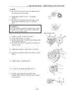
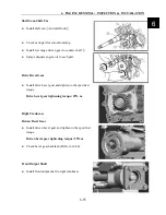
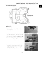
Install new o-ring in spacer
⑧
●
Install spacer onto the clutch housing shaft, then
install into CVT case
CVT Case
●
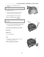
Install dowel pin
④
, gasket
②
and gasket
⑤
to the
right crankcase. Install CVT case assembly to right
crankcase.
●
Install bolt
⑿
and nut
③
●
Install air guide plate and screw
⑾
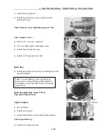
Primary Sheave, Secondary Sheave, Drive Belt
●
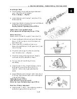
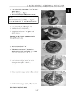
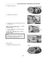
Install primary fixed sheave
①
as illustrated on the
right;
●
Install drive belt between secondary sliding/fixed
sheave and tap with a plastic hammer to keep the
belt as low as possible.
Note:
align oil nick on spacer with oil hole on the shaft.
Note:
●
Tighten bolt/nut diagonally.
●
Use a new gasket.
Note:
●
Install the drive belt with the arrow on the belt
turn in the clockwise direction
●
Drive belt contact surface should be free from any
stains.
6
Summary of Contents for XY500UTV
Page 1: ......
Page 2: ...Service Manual XY500UTV XY500LUTV XY500UE XY500UEL 4 4 ZHEJIANG XINYANG INDUSTRY CO LTD ...
Page 16: ...1 SERVICE INFORMATION 1 13 Cables Pipes Cable Routing 1 ...
Page 17: ...1 SERVICE INFORMATION 1 14 ...
Page 18: ...1 SERVICE INFORMATION 1 15 Carburetor Condition 1 ...
Page 19: ...1 SERVICE INFORMATION 1 16 Carburetor Condition EFI Condition ...
Page 20: ...1 SERVICE INFORMATION 1 17 Carburetor Condition 1 ...
Page 21: ...1 SERVICE INFORMATION 1 18 ...
Page 41: ...2 VEHICLE BODY MUFFLER 2 20 Description of visible parts ...
Page 44: ......
Page 66: ...4 COOLING AND LUBRICATIING SYSTEM 4 2 Cooling System Illustration 4 ...
Page 114: ...6 ENGINE REMOVAL INSPECTION INSTALLATION 6 29 Primary and Secondary Sheave 6 ...
Page 225: ......

