1. SERVICE INFORMATION
1-11
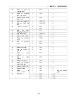
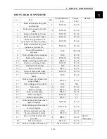
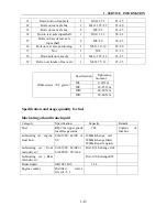
FRONT, REAR SUSPENSION
:
s.q. Item
Qty.
Thread diameter
mm
Torque
(
N·m
)
Remark
1
Bolts on front steering joint
and absorber
4
M12×60 45~50
2
Bolts on front and rear brake
disk
16
M10×30 45~50
3
Bolts on front brake Caliper
4
M10×30
45~50
4
Bolts on rear brake Caliper
4
M12×30
55~60
5
Bolts on support frame of
front and rear break sub-pumps
4
M12×20 55~60
`
6
Bolts on front steering joint
connector and beam pin
2
M10×30 45~50
7
Nuts of front and rear
sub-axles
4
M18 180~200
8
Nuts of pulling rode connector
2
M10
45~50
9
Bolts on Steering assy
4
M10×30
45~50
10
Bolts on steering transfer fork
2
M8×25
23~25
11
Screws on steering column
2
M10×25
45~50
12
Nuts on front absorber
2
M8
23~25
13
Screw of winch
4
M8×16
23~25
14
Screw of main brake pump
2
M10×60
45~50
15
Bolt on push rode of main
brake
1
M10 45~50
16
Bolt on beam pin of push rode
of main brake
1
M8×20 23~25
17
Nuts of flange of drive shaft
4
M14
100
18
Nuts on tyre
16
M12
55~62
19
Bolts on ceiling
4
M8×55
20~25
20
Bolts on hand brake
2
M8×20
20~25
21
Bolts on bumper
2
M10×20
50
22
Bolts on driving axle
2
M8×25
30
23
Bolts on flange and rear wheel
upper swing arm
1
M12×90 45~50
24
Bolts on flange and rear wheel
lower swing arm
2
M12×180 45~50
25
Nuts on front axle gear box
2
M10
45~50
26
Screw on front axle motor
4
M8×20
10~13
27
Screw on front and rear axle
pin shaft
12
M8×22 20~25
Spread
thread glue
29
Nut on front axle
1
M14×1.5
55~62
30
Bolt on oil intake of front axle
1
M14×1.25×12
23~25
1
Summary of Contents for XY500UTV
Page 1: ......
Page 2: ...Service Manual XY500UTV XY500LUTV XY500UE XY500UEL 4 4 ZHEJIANG XINYANG INDUSTRY CO LTD ...
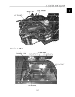
Page 16: ...1 SERVICE INFORMATION 1 13 Cables Pipes Cable Routing 1 ...
Page 17: ...1 SERVICE INFORMATION 1 14 ...
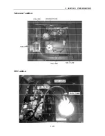
Page 18: ...1 SERVICE INFORMATION 1 15 Carburetor Condition 1 ...
Page 19: ...1 SERVICE INFORMATION 1 16 Carburetor Condition EFI Condition ...
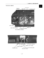
Page 20: ...1 SERVICE INFORMATION 1 17 Carburetor Condition 1 ...
Page 21: ...1 SERVICE INFORMATION 1 18 ...
Page 41: ...2 VEHICLE BODY MUFFLER 2 20 Description of visible parts ...
Page 44: ......
Page 66: ...4 COOLING AND LUBRICATIING SYSTEM 4 2 Cooling System Illustration 4 ...
Page 114: ...6 ENGINE REMOVAL INSPECTION INSTALLATION 6 29 Primary and Secondary Sheave 6 ...
Page 225: ......

