SmartPad LCD
Page:
19
© 2003 Xantech Corporation
INSTALLING SPLCD INTO BACK-BOX
Note:
The SmartPad LCD
can be programmed for
Upper
or
Lower
viewing angles. Depending upon
which viewing angle the display was programmed for, effects the orientation of the display in the back box.
Displays programmed for
Upper
viewing angle need to be installed with the IR Receiver PCA located on the
right
side and displays programmed for
Lower
viewing angle need to be installed with the IR Receiver PCA
located on the
left
side. (see
Figures 3a, 3b & 3c
)
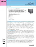
1. Pull all wires through the wire-access hole in the Back Box leaving slack for strain-relief and connect to
appropriate ports on rear of the SPLCD Display.
2. Insert SPLCD into Back Box oriented according to desired viewing angle so that the unit is flush within
the Back Box.
3. Secure with four 6-32x¼” screws (Part No. 103497).
Note:
Do not completely tighten screws.
4. Make sure display is level within the box and finish tightening screws. Be sure not to
over-tighten
.
5. Install front Bezel making sure all four tabs are properly aligned and inserted into their corresponding
Bezel Mounting Clips. (See
Figure – 11 Detail A
)
6. Push Bezel gently into mounting clips until flush with the wall making sure
side
tabs go through slots on
metal bracket.
Detail A
Side View
STEP 3
STEP 5
6-32x¼ Screws
BEZEL TAB
MOUNTING CLIP
Figure 11 – Installing SPLCD into Back Box