background image

WORKSHOP MANUAL

Winget Mechanically Fed Mixers

Models: 200TM

From 1998

crankshaft bearings.  A chain running too slack may run off the sprocket or
chainwheel.

Adjust the dynamo drive  “V” belt tension (if fitted) by altering the position of the
dynamo on the slotted adjuster so the belt deflects approximately 12mm, check
midway between the pulleys.

Refit the guards, not forgetting the plastic plug, top plate closing plate, exhaust
extension and engine housing support bracket.

Dynamo Drive Pulley Removal/Replacement

If a dragline option is fitted an alloy “V” belt drive pulley is fitted onto the extension
shaft prior to the sprocket.

To remove follow the above procedure and remove the engine sprocket and dynamo
drive belt, mark the position of the pulley on the shaft. Undo the grubscrew retaining
the pulley and slide off the pulley.

Reverse the procedure to fit the new pulley smearing the bore with anti-seize
compound prior to fitting.

Check the drive chain alignment and tension as described above, adjust the dynamo
drive  “V” belt tension by altering the position of the dynamo on the slotted adjuster
so the belt deflects approximately 12mm, check midway between the pulleys.

Refit the guards, not forgetting the plastic plug, top plate closing plate, exhaust
extension and engine housing support bracket.

Hydraulic Pump Removal/Replacement-Hydraulic PTO (Not Direct Drive)

The hydraulic pump is secured via four studs to an adapter plate, which is in turn
bolted to the engine gearcover, and it is not possible to remove the pump without
removing the backplate. The pump is driven by a gear mounted on the pump shaft, it
being driven by a gear bolted to the end of the crankshaft. The pump being clockwise
rotation.

Ensure any residual hydraulic pressure is dissipated as previously described. Place a
suitable container below the hydraulic pump to catch any hydraulic and engine oil
spills, remove and plug the supply and feed hoses and plug the ports in the pump to
prevent the ingress of dirt and foreign matter.

Remove the four nuts and bolts securing the backplate to the engine and carefully
remove the pump and backplate assembly. Note early backplates are fitted with a
gasket between the plate and gearcover whilst later engines have an ‘O’ Ring fitted.

Hold the assembly in a suitable soft jawed vice and bend back the tabs on the
tabwasher locking the driven gear retaining nut. Remove the nut and any washers,

Summary of Contents for 200TM

Page 1: ...HOP MANUAL 200TM MIXER WINGET LIMITED PO BOX 41 EDGEFOLD INDUSTRIAL ESTATE PLODDER LANE BOLTON LANCS BL4 OLR Tel 44 0 1204 854650 service winget co uk parts winget co uk www winget co uk FROM 1998 ISS...

Page 2: ...3 General Arrangement Dimensions Section 4 Service Schedules Lubrication Diagram Section 5 Hydraulic Circuit Diagrams Section 6 Wiring Diagrams Section 7 Noise Levels Section 8 Special Tools Section 9...

Page 3: ...WORKSHOP MANUAL 200TM SECTION 1 INTRODUCTION...

Page 4: ...ted Oils Fuels Silicone Sealer and Open Gear Lubricants can cause skin diseases if allowed to contaminate the skin Always apply barrier creams wear suitable protective clothing or when contamination i...

Page 5: ...prior to installation Carefully remove a seal pack the bearing with grease and refit the seal ensuring it is correctly seated 3 Apart from installing the electric motor mounting brackets and conduit...

Page 6: ...WORKSHOP MANUAL 200TM SECTION 2 REPAIR SERVICE PROCEDURES...

Page 7: ...ls are fitted with a removable needle bearing which can be grease via the grease point Reverse the procedure to replace a wheel not forgetting to lubricate the stub shaft and needle bearings with grea...

Page 8: ...m the drum base use suitably sized circlip pliers and remove the large circlip retaining the lower shaft bearing into the gear Remove the setscrews securing the bevel gear and shaft assembly to the dr...

Page 9: ...sealer and hardened concrete from the drum flange The 200T and 200TM both utilise the same drum cone however because the TS TR1 diesel version of the 200TM rotates in the opposite direction to the 20...

Page 10: ...T THE CLIP AROUND THE DRUM AS SHOWN RUN A BEAD OF SEALER INSIDE THE DRUM CLIP PRIOR TO FITMENT LEAVING APPROXIMATELY 6 I50mm EACH END OF THE CLIP CLEAR OF SEALER CLAMP THE CLIP IN PLACE USING THE SPEC...

Page 11: ...finger tighten the bolts until all the bolts are in place Tighten the bolts The bolts should go into the drum from the outside and only round or dome headed bolts should be used Bevel Gear Guard Repl...

Page 12: ...200TM DRUM ADJUSTMENT...

Page 13: ...ound Tilting Bracket and Pinion With the Drum in the vertical position remove the lower tilting pinion guard Remove the four setscrews securing the tilting bracket taking care not to drop the retainin...

Page 14: ...engine and pull the new chain in place round the countershaft sprocket Remove the old chain and link Loop the new chain round the sprocket in the bevel pinion shaft and fit the new split link The open...

Page 15: ...heck the shaft turns freely Assemble the bevel pinion to the shaft fitting the gib head key The pinion is fitted to the longer shank of the shaft If correctly assembled the threaded holes in the casti...

Page 16: ...ossible to leave the trunnion assembly in place provided it is properly supported Remove the engine housing lid top plate engine housing chain guard and infill plate Slacken the two bolts through the...

Page 17: ...el V belt pulley pushing fully onto the shaft fit the gib head key Refit both the countershaft chain and the engine chain V belt ensuring that the open end of the split links point away from the norma...

Page 18: ...the relevant sections to set up bevel pinion journal front bearing drum etc Hydraulic Hopper Ram The single acting hopper ram is retained via two pivot pins to remove fully raise the hopper and engag...

Page 19: ...nd the inner baffles adjusted by holding the nut and turning the capscrew with an hexagon key until the gap between the baffles measures 0 889mm It is quite common for machines fitted with hose burst...

Page 20: ...s and indents in the inserts Insert the two capscrews with spring washers to lock the inserts in place Batchweigher Pivot The batchweigher pivot is fitted with replaceable bushes and is retained to th...

Page 21: ...one each end slide the inserts onto each end of the shaft and push home into the mainframe aligning the indents in the inserts with the threaded holes in the mainframe Refit the capscrews to prevent t...

Page 22: ...the engine motor until the hydraulic oil is up to normal working temperature check the engine speed it should read 1500 rpm another way is to count the drum revolutions the drum should rotate at 22 r...

Page 23: ...chain and engine housing support bracket If a dragline option is fitted remove the dynamo drive belt Remove the four bolts securing the engine to the bed and slide the engine backward allowing access...

Page 24: ...the belt deflects approximately 12mm check midway between the pulleys Refit the guards not forgetting the plastic plug top plate closing plate exhaust extension and engine housing support bracket Hydr...

Page 25: ...mp is mounted on a bracket bolted to the gear end cover and coupled to the engine by a toothed splined drive coupling with nylon driving sleeve The drive being transmitted from the engine by a cranksh...

Page 26: ...rainpipe and anti kick back starting handles in order to comply with local legislation For information on the starting handles refer to the engine operators handbook or engine workshop manual For deta...

Page 27: ...nect the battery Hydraulic Pump Removal Replacement Hydraulic PTO Not Direct Drive The hydraulic pump is secured via four studs to an adapter plate which is in turn bolted to the engine gearcover and...

Page 28: ...lace a suitable container below the hydraulic pump to catch any hydraulic oil spills remove the coupling guard held with a single setscrew and washers Remove and plug the supply and feed hoses and plu...

Page 29: ...ntershaft chainwheel and engine drive chain are replaced by a V belt and V drive pulley The motor is also mounted differently in that it is bolted to a height adjustable bedplate to allow for belt ten...

Page 30: ...lt pulley available separately to drive the dynamo is welded to the rear of the toothed adapter mounted on the motor Hydraulic Pump Removal Replacement Remove the engine housing closing plate Ensure a...

Page 31: ...e mainframe using the P clips setscrews nuts and washers Adjust the height of the loadcell so that the adjustable striker bolt through the pivot rest centrally on the loadcell Tighten the setscrews se...

Page 32: ...TION OF CRADLE BRACKET 12 ON CRADLE SO THAT CENTRE LINE OF PINS 16 17 LIES PARALLEL WITH LINKS 9 2 ADJUST STRIKER 18 SO THAT EQUAL CLEARANCES X ARE OBTAINED BETWEEN PIVOT SHAFT 3 AND SLOTS IN CRADLE 2...

Page 33: ...k Fill the tank with a measured amount of water normally 5 litres allowing the ball within the indicator tube to stabilise adjust the scale so that the 5 litre mark is aligned with the water level and...

Page 34: ...the main system relief valve has been set Disconnect the supply hose from the control block to the winch motor and fit a 0 3000psi gauge to the hose Ensure the electrical cable from the shovel to the...

Page 35: ...ator resistor and dynamo are not required Power is taken from terminal 2 on the start switch through two core cable via a two pin plug and socket through the shovel mounted switch back through the plu...

Page 36: ...stop the engine or electric motor and feed the loose end of the rope through the pulley on the end of the jib leg then round the back and between the double pulley on the top beam Bend the end of the...

Page 37: ...the engine or electric motor and move the hanging wire rope out of the path of the hopper and fully raise the hopper checking it clears the top beam and pulleys Operate the dragline check for hydraul...

Page 38: ...Basic The basic hydraulic system is simple in design consisting of an engine or electric motor driven hydraulic pump hydraulic tank containing the suction strainer a single spool control valve and a s...

Page 39: ...return spring and closing off the return port to the hydraulic tank On releasing the control lever to neutral during either the raising or lowering cycle hydraulic oil under pressure trapped in the li...

Page 40: ...200TM BLEED VALVE ASSEMBLY BLEED VALVE BODY SPRING RETURN TO HYDRAULIC TANK INLET FROM CONTROL VALVE FEED OUT TO HYDRAULIC CYLINDER USED IN CONJUCTION WITH BATCHWEIGHER...

Page 41: ...ank through the return line which terminates at the tee piece on the side of the tank The supply and return hoses supplying oil to the winch motor from the distribution block are ported within the blo...

Page 42: ...WORKSHOP MANUAL 200TM SECTION 3 GENERAL ARRANGEMENT DIMENSIONS...

Page 43: ...GENERAL ARRANGEMENT...

Page 44: ...DIMENSIONS...

Page 45: ...WORKSHOP MANUAL 200TM SECTION 4 SERVICE SCHEDULES LUBRICATION DIAGRAM...

Page 46: ...oil and fuel leaks Check clean replace air filter element After Work Top up fuel tank Clean out drum and hopper Wash down the mixer Drain the water tank Weekly 40 Hours The above and the following Dr...

Page 47: ...filler and breather clean if necessary Batchweigher Check Calibration Every 3 Months 300 Hours The above and the following Engine Change air filter element Change lubrication oil and filter Change fue...

Page 48: ...LUBRICATION POINTS...

Page 49: ...LUBRICANTS...

Page 50: ...WORKSHOP MANUAL 200TM SECTION 5 HYDRAULIC CIRCUIT DIAGRAMS...

Page 51: ...200TM LATER BASIC HYDRAULIC CIRCUIT...

Page 52: ...200TM LATER DRAGLINE BATCHWEIGER HYDRAULIC CIRCUIT...

Page 53: ...WORKSHOP MANUAL 200TM SECTION 6 WIRING DIAGRAMS...

Page 54: ...o allow connection of external Emergency Stop Button Link terminal 5 on upper face of Contactor to terminal 63NO Link terminal 95 on Overload Relay to terminal A2 on upper face of Contactor Link termi...

Page 55: ...T USED ON ELECTRIC START LISTER PETTER TS1 ENGINES ONLY ON HAND START ENGINES AND 415 VOLT ELECTRIC MOTORS TO SHOVEL DYNAMO TO SOLENIOD RESISTOR BLUE w BROWN U BROWN BLUE GREEN RED BROWN U BROWN Z BLU...

Page 56: ...INSULATING 1 6 555253800 CLAMP CABLE 1 7 82S07F SCREW ROUND HEAD 1 8 83S07 NUT 1 9 11S01A SCREW SET 2 10 17S02 WASHER SPRING 2 11 7S01 NUT 2 12 11S02B SCREW SET 2 13 267S04 WASHER FLAT 4 14 61SD2 NUT...

Page 57: ...Cable green 10 Cable red 11 Connector 12 Nipples 13 Cable twin core brown and blue 14 Socket shovel unit 15 Plug shovel unit 16 Control shovel unit 18 Dragline solenoid valve 19 Connect cable to solen...

Page 58: ...200TM DRAGLINE WIRING TS1 ES 1 2 3 4 5 SOCKET PLUG DRAGLINE DRAGLINE SWITCH BULLET CONNECTOR START SWITCH DRAGLINE SOLENOID VALVE...

Page 59: ...Hourmeter lamp dwg 04 03 02 12 50 36 Scaled to fit...

Page 60: ...Hourmeter no lamp dwg 04 03 02 12 53 33 Scaled to fit...

Page 61: ...00E 4S2500E 200TM 300R 400R 500R FFB COLLECTOR 1000 WIRING COLOUR CODES 1 STARTER MOTOR REG B 2 START SWITCH TER 1 STARTER MOTOR BROWN 3 START SWITCH TER 3 STARTER SOLENOID 4 START SWITCH TER 4 REG C...

Page 62: ...WORKSHOP MANUAL 200TM SECTION 7 NOISE LEVELS...

Page 63: ...n on a 10 metre hemisphere with the drum loaded and rotating Operators Ear Tests were carried out at a distance 1 metre from the Hopper and Handwheel at a height of 1 metre Lister Petter TS1 06 Standa...

Page 64: ...WORKSHOP MANUAL 200TM SECTION 8 SPECIAL TOOLS...

Page 65: ...200TM PUNCH VALVE SEAT 200TM SPECIAL TOOL V2003698 CASE HARDEN TO 45 50 ROCKWELL...

Page 66: ...200TM DRUM BLADE DRILLING GUIDE SPECIAL TOOL 200TM 513360100...

Page 67: ...200TM SPECIAL TOOLS...

Page 68: ...1 513204000 CLAMP DRUM CLIP 1 2 V2003698 PUNCH BLEED VALVE SEAT 1 200TM SPECIAL TOOLS...

Page 69: ...WORKSHOP MANUAL 200TM SECTION 9 HYDRAULIC CONTROL VALVE SERVICE MANUAL...

Page 70: ...PAGE INTENTIONALLY BLANK...

Page 71: ...WORKSHOP MANUAL 200TM SECTION 10 PARTS LISTINGS...

Page 72: ...s do not contain a breakdown of assemblies such as Hydraulic Winch Motor Hydraulic Ram etc only the complete items are shown For a breakdown of these items please refer to the attached Parts Microfich...

Page 73: ...200TM MAINFRAME AXLES AND STABILISERS...

Page 74: ...BINX 2 27 11S05D SCREW SET 2 30 513340100 AXLE REAR 1 31 11S05D SCREW SET 4 32 267S07 WASHER FLAT 4 33 61S05 NUT BINX 4 35 475122000 WHEEL PNEUMATIC 4 40 513198500 WHEEL STEEL 4 41 513324700 COLLAR 4...

Page 75: ...METAL PANELS AND GUARDS USE BLANK TOP PANEL ITEM 6 WITH ELECTRIC MOTOR DRIVEN MACHINES FIT SPACERS 555170000 BETWEEN ENGINE MOTOR COVER AND MAINFRAME ONE EACH SIDE ALTERNATIVELY USE V2004220 SPECIAL W...

Page 76: ...4 37 267S05 WASHER FLAT 4 38 17S04 WASHER SPRING 4 39 7S03 NUT 4 40 513350500 GUARD SPROCKET DIESEL 1 41 513336100 GUARD SPROCKET ELECTRIC 1 42 11S04B SCREW SET 1 2 43 17S05 WASHER SPRING 1 2 44 7S04...

Page 77: ...INE COVER NOT ILLUSTRATED 2 67 10538A02 CATCH PLATE NOT ILLUSTRATED 2 68 11S01AA SCREW SET NOT ILLUSTRATED 8 69 267S03 WASHER FLAT NOT ILLUSTRATED 8 70 59S13 NUT NYLOC NOT ILLUSTRATED 8 200TM SHEETMET...

Page 78: ...ND BORE OF ITEM 22 LIBERALLY WITH COPPERSLIP ON ASSEMBLY WHEN THE LOCKING PLUNGER ITEM 27 IS INSERTED INTO THE BEARING HOUSING ITEM 33 THE TRUNNION ITEM 1 SHOULD BE HORIZONTAL IN THE MAINFRAME THE DOW...

Page 79: ...SCREW SET 10 19 17S03 WASHER SPRING 10 20 131S02 NIPPLE GREASE 90 O 1 21 176S01 CAP NIPPLE 1 22 513323700 INSERT 1 23 513323800 PLATE 2 24 17S06 WASHER SPRING 2 25 7S05 NUT 1 26 513315400 WHEEL TILT...

Page 80: ...RIVE THE BEVEL PINION HOUSING SHOULD BE PERPENDICULAR TO THE REAR FACE OF THE TRUNNION WHEN CORRECTLY FITTED SPROCKETS 32 AND 20 MUST BE ALIGNED ON ASSEMBLY ADJUST POSITION OF ITEM 20 ON BEVEL PINION...

Page 81: ...10845 KEY TAPER GIB HEAD 1 22 134105070 CHAIN 1 23 134105002 LINK CONNECTING A R 24 134105001 LINK HALF A R 30 132725000 CIRCLIP 1 31 304708035 KEY FEATHER 1 32 513310500 SPROCKET 1 33 132362000 CIRCL...

Page 82: ...EM 15A OF VARYING THICKNESS AS NECESSARY EQUISPACED AROUND THE CIRCUMFERENCE OF THE BEVEL GEAR IN 6 8 POSITIONS THIS WILL ENSURE THAT WHEN THE RETAINING SCREWS ARE TIGHTENED THE CAST BEVEL GEAR WILL N...

Page 83: ...A R 15C 513371201 SHIM 0 5MM THICK A R 16 17S06 WASHER SPRING 6 16A 267S07 WASHER FLAT 6 17 11S05D SCREW SET 6 20 132760000 CIRCLIP 1 21 88S42D BEARING 1 22 132775000 CIRCLIP 1 23 88S45D BEARING 1 24...

Page 84: ...K BACK STARTING HANDLES THE CLOSED END OF THE SPRING CLIP ON THE DRIVE CHAIN MUST FACE IN THE DIRECTION OF ROTATION THE HEIGHT OF THE ENGINE MUST BE ADJUSTED USING THE SHIMS ILLUSTRATED SO THAT THE CH...

Page 85: ...3S08 CLAMP EXHAUST PIPE 1 12 267S05 WASHER FLAT 2 13 17S04 WASHER SPRING 2 15 513348300 SPROCKET 1 15A 57S05D2 SCREW GRUB 1 16 304312050 KEY GIB HEAD 1 17 134105102 CHAIN 1 18 134105002 LINK CONNECTIN...

Page 86: ...200TM 415 VOLT ELECTRIC MOTOR STAR DELTA THE MOTOR AND PUMP MUST BE ALIGNED TO AVOID PREMATURE FAILURE OF THE SLEEVE ITEM 12...

Page 87: ...B SCREW FITTED IN COUPLING 15 10977A05 PUMP 1 16 8S02C BOLT 1 17 267S04 WASHER FLAT 4 18 17S03 WASHER SPRING 4 19 7S02 NUT 4 20 513332800 PLATE MOUNT PUMP 1 21 11S03C SCREW SET 4 22 267S05 WASHER FLAT...

Page 88: ...200TM 415 VOLT ELECTRIC MOTOR DIRECT ON LINE THE MOTOR AND PUMP MUST BE ALIGNED TO AVOID PREMATURE FAILURE OF THE SLEEVE ITEM 12...

Page 89: ...B SCREW FITTED IN COUPLING 15 10977A05 PUMP 1 16 8S02C BOLT 1 17 267S04 WASHER FLAT 4 18 17S03 WASHER SPRING 4 19 7S02 NUT 4 20 513332800 PLATE MOUNT PUMP 1 21 11S03C SCREW SET 4 22 267S05 WASHER FLAT...

Page 90: ...200TM 415 VOLT START STOP SWITCH STAR DELTA...

Page 91: ...271000 COUPLING KOPEX 20MM 2 6A 131272000 COUPLING KOPEX 25MM 2 7 133272000 NUT BACK THIN 2 7A 133275050 NUT BACK THIN 1 8 144797000 CABLE RED 1 METRE 9 144799000 CABLE GREEN YELLOW 1 METRE 10 1447980...

Page 92: ...200TM 415 VOLT START STOP SWITCH DIRECT ON LINE...

Page 93: ...6 131271000 COUPLING KOPEX 20MM 4 7 133272000 NUT BACK THIN M20 4 8 144797000 WIRE RED 1 5 METRE 9 144799000 WIRE GREEN YELLOW 1 5 METRE 10 144798000 WIRE BLACK 1 5 METRE 15 208880000 SWITCH STOP 1 1...

Page 94: ...200TM HOPPER CRADLE BASIC NON WEIGHER COAT ALL PINS AND BEARINGS WITH COPPERSLIP BEFORE INSTALLATION...

Page 95: ...SET 1 6 68S04D SCREW SPROCKET HD CAP 2 7 131S01 NIPPLE GREASE 2 8 17601 CAP NIPPLE 2 10 513369100 HOPPER RAM METRIC 1 11 513312900 PIN RAM LOWER 1 12 513313000 PIN RAM UPPER 1 13 8S03F BOLT 2 14 61S0...

Page 96: ...GHER ITEMS 22 AND 30 MUST BE FREE WHEN FITTED THE BRACKET ITEM 20 SHOULD BE ADJUSTED SO THAT THE ROLLER ITEM 22 ENGAGES WITH THE PIVOT ITEM 30 WHEN THE HOPPER IS FULLY LOWERED COAT ALL PINS AND BUSHES...

Page 97: ...T CAP 2 20 513322200 BRACKET CRADLE 1 21 513317400 PIN 1 22 513317200 ROLLER 1 23 112753000 BUSH 2 24 57S05E2 GRUB SCREW 1 25 11S05C SCREW SET 4 26 267S07 WASHER FLAT 4 27 61S05 NUT BINX 4 30 51332100...

Page 98: ...200TM HOPPER...

Page 99: ...1 513310900 HOPPER ASSEMBLY 1 2 172S05D BOLT COACH 8 3 267S07 WASHER FLAT 8 4 61S05 NUT BINX 8 200TM HOPPER...

Page 100: ...M BLEED VALVE PORT 8 TO DRAGLINE VALVE BLOCK IF NO DRAGLINE IS FITTED PORT 8 IS PLUGGED WITH ITEM 9 WHEN A DRAGLINE IS FITTED ITEM 7 THE H P C O SHOULD BE SCREWED FULLY HOME INTO THE VALVE PORT FOLLOW...

Page 101: ...TO TANK 1 6 122S03 ADAPTOR M M TO RAM 1 7 V2004607 SCREW SOCKET HEAD H P C D FIT INSIDE VALVE WHEN DRAGLINE FITTED 1 8 122S03 ADAPTOR M M WHEN DRAGLINE FITTED 1 9 127S03 PLUG BLANKING WHEN NO DRAGLIN...

Page 102: ...STRATION ON SEPARATE PAGE FOR CORRECT PIPING CONNECTION SEQUENCE THE HOSE FAILURE VALVE ITEM 52 IS ONLY FITTED TO EUROPEAN SPEC CE MARKED MODELS THE VALVE MUST BE SET BEFORE INSTALLATION REFER TO THE...

Page 103: ...TRIC 1 26 122S04 ADAPTOR 1 27 100S04 SEAL BONDED 1 30 513329800 HOSE PUMP TO CONTROL VALVE 1 31 100S04 SEAL BONDED 1 32 119S08 ADAPTOR M M 1 35 31S02G HOSE CONTROL VALVE TO TANK 1 36 122S03 ADAPTOR M...

Page 104: ...SCREW ITEM 17 WITH HYDRAULIC SEALER TO PREVENT ENGINE OIL LEAKAGE VIA THREADS ENSURE THE EXTENSION SHAFT ITEM 2 IS SEATED FULLY DOWN ON THE FACE OF THE CRANKSHAFT WHEN TIGHTENED ONTO THE STUD ITEM 1 O...

Page 105: ...06385 BRACKET PUMP MOUNTING 1 11 8S03N BOLT M8 X 90 3 12 17S04 WASHER SPRING 3 13 267S05 WASHER FLAT 3 14 513340800 SPACER TWO PER BOLT BETWEEN BRACKET GEAR COV 6 15 V2006389 COUPLING ASSEMBLY CONSIST...

Page 106: ...IT BATCHWEIGHER REFER TO SEPARATE PAGE FOR CONTROL VALVE ILLUSTRATION REFER TO THE ASSEMBLY INSTRUCTIONS IN THE FRONT OF THIS MANUAL AND USE THE SPECIAL TOOL TO ENSURE A GOOD SEAT IS FORMED IN THE BLE...

Page 107: ...13 122S03 ADAPTOR M M 1 14 100S03 SEAL BONDED 1 15 36S02VV HOSE 1 16 122S03 ADAPTOR M M 1 17 100S03 SEAL BONDED 1 18 122S03 ADAPTOR M M 1 19 100S03 SEAL BONDED 1 20 36S02TT HOSE 1 21 119S03 ADAPTOR 2...

Page 108: ...IS THE EXISTING FIXING SECURING THE CONTROL VALVE COVER THE LOADCELL IS SECURED TO THE MAINFRAME USING ITEMS 28 29 30 SETSCREW SPRING AND FLAT WASHER THE LOADCELL IS ALSO PREVENTED FROM MOVING BY A S...

Page 109: ...1 22 261S02M SCREW THUMB 4 23 513327700 BRACKET MOUNTING 1 24 513327800 BRACKET MOUNTING 1 25 16S05B SCREW SET PAN HEAD 2 26 143200900 CLIP NYLON 2 26A 267S02 WASHER FLAT 2 26B 17S10 WASHER SPRING 2 2...

Page 110: ...200TM WATER TANK FIT SPECIAL WASHER V2004220 BETWEEN ITEMS 11 12...

Page 111: ...13286400 CHAIN RING 1 14 383106000 RING SPLIT 1 15 513324600 SCALE 1 16 70S04D SCREW PAN HEAD 2 17 59S13 NUT NYLOC 2 19 430904001 TUBE 1 20 132111200 CLIP HOSE 2 21 101256000 BALL 1 22 450150000 VALVE...

Page 112: ...ONNECTORS ON BOTH ENDS OF THE PRESSURE LINE MUST BE HIGHLIGHTED WITH RED PAINT TO AVOID CONFUSION WHEN THE MACHINE IS BEING INSTALLED ON SITE WHEN LOOKING DIRECTLY AT THE END OF THE MOTOR SHAFT THE SH...

Page 113: ...FOLD DRAGLINE 1 14 555138300 VALVE RELIEF 1 15 555556100 SPRING 1 16 10S02 WASHER FLAT 1 17 100S04 SEAL BONDED 1 18 555138200 VALVE GUIDE 1 20 66S01AA SCREW SET 2 21 41S03 WASHER SPRING 2 22 10S01 WAS...

Page 114: ...200TM DYNAMO AND MOUNTING LISTER PETTER TS1 HS...

Page 115: ...SCREW SET 2 7 17S04 WASHER SPRING 4 8 7S03 NUT 2 10 513347400 ADJUSTER DYNAMO 1 11 66S03A SCREW SET 1 12 41S05 WASHER SPRING 1 13 66S02CC SCREW SET 1 14 41S04 WASHER SPRING 1 15 10S02 WASHER FLAT 1 20...

Page 116: ...MO 415 VOLT MOTOR THE HYDRAULIC PUMP AND ELECTRIC MOTOR SHOULD BE CORRECTLY ALIGNED TO PREVENT PREMATURE FAILURE OF THE NYLON COUPLING SLEEVE CHECK THAT THE TWO PULLIES ARE ALIGNED AND THE V BELT IS C...

Page 117: ...Y DYNAMO 1 4 513350600 PULLEY DYNAMO DRIVE 28MM 1 5 397436000 BELT VEE 1 6 11S03C SCREW SET 5 7 7S03 NUT 5 8 17S04 WASHER SPRING 5 9 66S02CC SCREW SET 1 10 41S04 WASHER SPRING 1 11 10S02 WASHER FLAT 1...

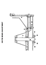
Page 118: ...200TM DRAGLINE ASSEMBLY...

Page 119: ...555265000 PIN PULLEY 2 27 44S17K PIN SPLIT 3 28 131S01 NIPPLE GREASE 2 28A 176S01 CAP NIPPLE 2 29 513330000 PIN PIVOT 1 30 555228100 BRACKET PULLEY 1 31 513330300 MAST ELECTRIC CABLE 1 33 555208400 PU...

Page 120: ...200TM DRAGLINE ASSEMBLY...

Page 121: ...59 267S04 WASHER FLAT 21 60 332719000 NUT SPIRE 3 61 61S02 NUT BINX 9 62 17S03 WASHER SPRING 3 63 267S07 WASHER FLAT 1 200TM DRAGLINE...

Page 122: ...T USED ON ELECTRIC START LISTER PETTER TS1 ENGINES ONLY ON HAND START ENGINES AND 415 VOLT ELECTRIC MOTORS TO SHOVEL DYNAMO TO SOLENIOD RESISTOR BLUE w BROWN U BROWN BLUE GREEN RED BROWN U BROWN Z BLU...

Page 123: ...INSULATING 1 6 555253800 CLAMP CABLE 1 7 82S07F SCREW ROUND HEAD 1 8 83S07 NUT 1 9 11S01A SCREW SET 2 10 17S02 WASHER SPRING 2 11 7S01 NUT 2 12 11S02B SCREW SET 2 13 267S04 WASHER FLAT 4 14 61SD2 NUT...

Page 124: ...200TM DRAGLINE SHOVEL...

Page 125: ...143200300 CLIP CABLE 1 9 144734000 CABLE 1 10 16S05B SCREW PAN HEAD 1 11 17S02 WASHER SPRING 2 12 205304600 PLUG 1 13 208143000 SLEEVE 55MM LONG 1 14 208561000 SWITCH 1 15 250166010 GLAND CABLE 1 16...

Page 126: ...200TM DRAGLINE FEEDAPRON...

Page 127: ...IDE R H 1 4 513337000 PANEL PARTITION 1 5 513332300 RETAINER COUNTER SUNK 1 6 52S04G SCREW COUNTER SUNK 9 7 7S04 NUT 9 8 17S05 WASHER SPRING 9 9 513332500 TRIM RUBBER 1 10 513336700 ANGLE TIE 1 11 11S...

Page 128: ...200TM BATTERY TRAY LISTER PETTER TS1 ES WELD TRAY TO THE REAR OF THE MAINFRAME BELOW THE ENGINE HOUSING...

Page 129: ...5 CLAMP BATTERY 1 12 11S04B SCREW SET 2 13 7S04 NUT 2 14 17S05 WASHER SPRING 2 15 267S06 WASHER FLAT 2 16 61S02 NUT BINX 2 17 267S04 WASHER FLAT 2 18 V2004120 ROD CLAMP 2 19 513358500 TRAY BATTERY 1 2...

Page 130: ...200TM LISTER PETTER TS1 ELECTRIC START...

Page 131: ...PANEL INSTRUMENT 1 6A 11S04B SCREW SET NOT ILLUSTRATED 2 6B 7S04 NUT NOT ILLUSTRATED 2 6C 17S05 WASHER SPRING NOT ILLUSTRATED 2 7 LIGHT WARNING 1 10 START SWITCH 1 11 START KEYS 2 ITEMS 7 10 11 SUPPL...

Page 132: ...200TM DECALS AND LOGOS 1 2 3 4 5 6 7 8 9 10 11 12 13 14 15 16 17 18 19 20 21 22...

Page 133: ...V2004137 DECAL EAR PROTECTION 2 14 V2003665 DECAL SLING POINT 2 15 V2003598 DECAL BRITISH MADE 1 16 10166A02 DECAL TYRE PRESSURES 4 17 V2004227 DECAL BATTERY ISOLATOR 1 18 V2004229 DECAL OPS BOOK 2 19...

Page 134: ...200TM DECALS AND LOGOS 23 24 25 26 27 28 29...

Page 135: ...200TM SPECIAL TOOLS...

Page 136: ...1 513204000 CLAMP DRUM CLIP 1 2 V2003698 PUNCH BLEED VALVE SEAT 1 200TM SPECIAL TOOLS...

Page 137: ...WORKSHOP MANUAL 200TM SECTION 11 BATCHWEIGHER MAINTENANCE INSTRUCTIONS...

Page 138: ...MAINTENANCE INSTRUCTIONS HYDRAULIC WEIGHING UNITS WWW WINGET CO UK...

Page 139: ...the fact that this advice is not always practicable Winget Limited have released this manual subject to the disclaimer below The contents of this manual although correct at the time of publication ma...

Page 140: ......

Page 141: ......

Page 142: ......

Page 143: ......

Page 144: ......

Page 145: ......

Page 146: ......

Page 147: ......

Page 148: ...WORKSHOP MANUAL 200TM SECTION 12 18 BLANK...

Page 149: ...RNIA CALIFORNIA CALIFORNIA CALIFORNIA Proposition 65 Warning Diesel engine exhaust and some of its constituents are known to the State of California to cause cancer birth defects and other reproductiv...

Reviews: