WORKSHOP MANUAL
Winget Mechanically Fed Mixers
Models: 200TM
From 1998
Unbolt the jib top beam from both jib legs, unbolt and remove both jib legs refit all
setscrews and bolts back into the jib legs and top beam to prevent loss.
Feed Apron
Two Compartment Feed Aprons are designed to assist the flow of materials into the
hopper in conjunction with a dragline shovel.
The feed apron consists of L/H and R/H side panels, base panel, centre divider,
support bar, rubber flap, (to prevent materials falling between the hopper and apron)
and rubber flap retaining bar.
To assemble the feed apron, place the base smooth side up in front of the hopper,
lay the rubber flap on the base and secure with the retainer and countersunk screws.
Using a suitable support raise the base so that rubber is approximately 470
millimetres (18”) off the ground and the base slopes back at an angle, both bolt the
side panels in place. Remove the support so the weight of the base is taken by the
side panels. Fit the support bar between the side panels and bolt the centre divider
in place.
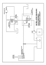
Hydraulic System Description – Basic
The basic hydraulic system is simple in design consisting of an engine or electric
motor driven hydraulic pump, hydraulic tank containing the suction strainer, a single
spool control valve and a single acting hydraulic cylinder onto which is mounted the
hose burst valve. The hose burst valves are only fitted to those machines intended
for use within the European Community or the USA. Early single acting rams have a
cylinder with an open to atmosphere breather, later rams have the breather piped
directly back to the hydraulic tank.
The pump draws oil from the tank through the suction strainer and delivers the oil to
the control valve, if the valve control lever is in the neutral position the oil is directed
back to the tank through the return port.
If the lever is raised oil is directed to the hydraulic cylinder which raises the hopper,
the maximum pressure being dictated by the adjustable relief valve contained within
the control valve.
If the lever is lowered the weight of the hopper displaces oil out of the cylinder back
through the valve out through the return port to the tank.
If the lever is returned to the neutral position during the lowering cycle the return port
is closed and oil is trapped between the cylinder and spool preventing the hopper
from dropping.
Summary of Contents for 200TM
Page 3: ...WORKSHOP MANUAL 200TM SECTION 1 INTRODUCTION...
Page 6: ...WORKSHOP MANUAL 200TM SECTION 2 REPAIR SERVICE PROCEDURES...
Page 12: ...200TM DRUM ADJUSTMENT...
Page 42: ...WORKSHOP MANUAL 200TM SECTION 3 GENERAL ARRANGEMENT DIMENSIONS...
Page 43: ...GENERAL ARRANGEMENT...
Page 44: ...DIMENSIONS...
Page 45: ...WORKSHOP MANUAL 200TM SECTION 4 SERVICE SCHEDULES LUBRICATION DIAGRAM...
Page 48: ...LUBRICATION POINTS...
Page 49: ...LUBRICANTS...
Page 50: ...WORKSHOP MANUAL 200TM SECTION 5 HYDRAULIC CIRCUIT DIAGRAMS...
Page 51: ...200TM LATER BASIC HYDRAULIC CIRCUIT...
Page 52: ...200TM LATER DRAGLINE BATCHWEIGER HYDRAULIC CIRCUIT...
Page 53: ...WORKSHOP MANUAL 200TM SECTION 6 WIRING DIAGRAMS...
Page 59: ...Hourmeter lamp dwg 04 03 02 12 50 36 Scaled to fit...
Page 60: ...Hourmeter no lamp dwg 04 03 02 12 53 33 Scaled to fit...
Page 62: ...WORKSHOP MANUAL 200TM SECTION 7 NOISE LEVELS...
Page 64: ...WORKSHOP MANUAL 200TM SECTION 8 SPECIAL TOOLS...
Page 65: ...200TM PUNCH VALVE SEAT 200TM SPECIAL TOOL V2003698 CASE HARDEN TO 45 50 ROCKWELL...
Page 66: ...200TM DRUM BLADE DRILLING GUIDE SPECIAL TOOL 200TM 513360100...
Page 67: ...200TM SPECIAL TOOLS...
Page 68: ...1 513204000 CLAMP DRUM CLIP 1 2 V2003698 PUNCH BLEED VALVE SEAT 1 200TM SPECIAL TOOLS...
Page 69: ...WORKSHOP MANUAL 200TM SECTION 9 HYDRAULIC CONTROL VALVE SERVICE MANUAL...
Page 70: ...PAGE INTENTIONALLY BLANK...
Page 71: ...WORKSHOP MANUAL 200TM SECTION 10 PARTS LISTINGS...
Page 73: ...200TM MAINFRAME AXLES AND STABILISERS...
Page 90: ...200TM 415 VOLT START STOP SWITCH STAR DELTA...
Page 92: ...200TM 415 VOLT START STOP SWITCH DIRECT ON LINE...
Page 98: ...200TM HOPPER...
Page 110: ...200TM WATER TANK FIT SPECIAL WASHER V2004220 BETWEEN ITEMS 11 12...
Page 114: ...200TM DYNAMO AND MOUNTING LISTER PETTER TS1 HS...
Page 118: ...200TM DRAGLINE ASSEMBLY...
Page 120: ...200TM DRAGLINE ASSEMBLY...
Page 124: ...200TM DRAGLINE SHOVEL...
Page 126: ...200TM DRAGLINE FEEDAPRON...
Page 130: ...200TM LISTER PETTER TS1 ELECTRIC START...
Page 132: ...200TM DECALS AND LOGOS 1 2 3 4 5 6 7 8 9 10 11 12 13 14 15 16 17 18 19 20 21 22...
Page 134: ...200TM DECALS AND LOGOS 23 24 25 26 27 28 29...
Page 135: ...200TM SPECIAL TOOLS...
Page 136: ...1 513204000 CLAMP DRUM CLIP 1 2 V2003698 PUNCH BLEED VALVE SEAT 1 200TM SPECIAL TOOLS...
Page 137: ...WORKSHOP MANUAL 200TM SECTION 11 BATCHWEIGHER MAINTENANCE INSTRUCTIONS...
Page 138: ...MAINTENANCE INSTRUCTIONS HYDRAULIC WEIGHING UNITS WWW WINGET CO UK...
Page 140: ......
Page 141: ......
Page 142: ......
Page 143: ......
Page 144: ......
Page 145: ......
Page 146: ......
Page 147: ......


