


WORKSHOP MANUAL
Winget Mechanically Fed Mixers
Models: 200TM
From 1998
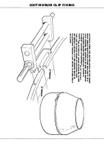
piece over the remaining gap in the drum clip and weld in place. Remove the tool.
Fully tighten the drum blades.
Run the mixer, tilting the drum via the tiltwheel making sure that the drum, clip or
bridge piece do not foul the mainframe or guards.
Stop the engine, clean any excess silicone off the drum or clip.
Drum Blade Replacement
It is unlikely that drum blades will require replacement separately to the drum cone.
However in the event that it should prove necessary, clean any hardened concrete or
mortar from around the bolts securing the blades. Remove the bolts and blades. Due
to the corrosive action of concrete and mortar it may be necessary to cut through the
old bolts using oxyacetylene equipment. Be aware that hot concrete can “explode”
violently spitting concrete - wear suitable eye protection and protective clothing.
Attach the new blades into the drum assembly finger tighten the bolts until all the
bolts are in place. Tighten the bolts.
The bolts should go into the drum from the outside and only round or dome headed
bolts should be used.
Bevel Gear Guard Replacement
Remove the drum assembly as previously described. Remove the four setscrews,
nuts, etc. holding the guard in place. Fit the new guard tighten the setscrews.
Replace the drum assembly as described below.
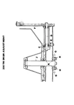
Refitting Drum Assembly
Using suitable lifting equipment lift the drum assembly, check the drum shaft is clean
and referring to the Drum Adjustment illustration coat the drum shaft
(J)
and trunnion
with anti-seize compound at
(A)
.
Turn the drum shaft so the threaded holes in the base of the shaft are at 90 degrees
to those in the trunnion base blocks.
Position the drum over the trunnion and lower into place making sure the bevel gear
and pinion are fully in mesh and the drum is fully seated down.
Apply anti-seize compound to the drum shaft setscrews and secure the flange to the
drum shaft not forgetting the tabwasher. Using the flange turn the drum shaft until
the remaining holes in the flange align with the holes in the base block.
Summary of Contents for 200TM
Page 3: ...WORKSHOP MANUAL 200TM SECTION 1 INTRODUCTION...
Page 6: ...WORKSHOP MANUAL 200TM SECTION 2 REPAIR SERVICE PROCEDURES...
Page 12: ...200TM DRUM ADJUSTMENT...
Page 42: ...WORKSHOP MANUAL 200TM SECTION 3 GENERAL ARRANGEMENT DIMENSIONS...
Page 43: ...GENERAL ARRANGEMENT...
Page 44: ...DIMENSIONS...
Page 45: ...WORKSHOP MANUAL 200TM SECTION 4 SERVICE SCHEDULES LUBRICATION DIAGRAM...
Page 48: ...LUBRICATION POINTS...
Page 49: ...LUBRICANTS...
Page 50: ...WORKSHOP MANUAL 200TM SECTION 5 HYDRAULIC CIRCUIT DIAGRAMS...
Page 51: ...200TM LATER BASIC HYDRAULIC CIRCUIT...
Page 52: ...200TM LATER DRAGLINE BATCHWEIGER HYDRAULIC CIRCUIT...
Page 53: ...WORKSHOP MANUAL 200TM SECTION 6 WIRING DIAGRAMS...
Page 59: ...Hourmeter lamp dwg 04 03 02 12 50 36 Scaled to fit...
Page 60: ...Hourmeter no lamp dwg 04 03 02 12 53 33 Scaled to fit...
Page 62: ...WORKSHOP MANUAL 200TM SECTION 7 NOISE LEVELS...
Page 64: ...WORKSHOP MANUAL 200TM SECTION 8 SPECIAL TOOLS...
Page 65: ...200TM PUNCH VALVE SEAT 200TM SPECIAL TOOL V2003698 CASE HARDEN TO 45 50 ROCKWELL...
Page 66: ...200TM DRUM BLADE DRILLING GUIDE SPECIAL TOOL 200TM 513360100...
Page 67: ...200TM SPECIAL TOOLS...
Page 68: ...1 513204000 CLAMP DRUM CLIP 1 2 V2003698 PUNCH BLEED VALVE SEAT 1 200TM SPECIAL TOOLS...
Page 69: ...WORKSHOP MANUAL 200TM SECTION 9 HYDRAULIC CONTROL VALVE SERVICE MANUAL...
Page 70: ...PAGE INTENTIONALLY BLANK...
Page 71: ...WORKSHOP MANUAL 200TM SECTION 10 PARTS LISTINGS...
Page 73: ...200TM MAINFRAME AXLES AND STABILISERS...
Page 90: ...200TM 415 VOLT START STOP SWITCH STAR DELTA...
Page 92: ...200TM 415 VOLT START STOP SWITCH DIRECT ON LINE...
Page 98: ...200TM HOPPER...
Page 110: ...200TM WATER TANK FIT SPECIAL WASHER V2004220 BETWEEN ITEMS 11 12...
Page 114: ...200TM DYNAMO AND MOUNTING LISTER PETTER TS1 HS...
Page 118: ...200TM DRAGLINE ASSEMBLY...
Page 120: ...200TM DRAGLINE ASSEMBLY...
Page 124: ...200TM DRAGLINE SHOVEL...
Page 126: ...200TM DRAGLINE FEEDAPRON...
Page 130: ...200TM LISTER PETTER TS1 ELECTRIC START...
Page 132: ...200TM DECALS AND LOGOS 1 2 3 4 5 6 7 8 9 10 11 12 13 14 15 16 17 18 19 20 21 22...
Page 134: ...200TM DECALS AND LOGOS 23 24 25 26 27 28 29...
Page 135: ...200TM SPECIAL TOOLS...
Page 136: ...1 513204000 CLAMP DRUM CLIP 1 2 V2003698 PUNCH BLEED VALVE SEAT 1 200TM SPECIAL TOOLS...
Page 137: ...WORKSHOP MANUAL 200TM SECTION 11 BATCHWEIGHER MAINTENANCE INSTRUCTIONS...
Page 138: ...MAINTENANCE INSTRUCTIONS HYDRAULIC WEIGHING UNITS WWW WINGET CO UK...
Page 140: ......
Page 141: ......
Page 142: ......
Page 143: ......
Page 144: ......
Page 145: ......
Page 146: ......
Page 147: ......


