WORKSHOP MANUAL
Winget Mechanically Fed Mixers
Models: 200TM
From 1998
The shafts appear identical but the hopper cradle shaft has a longer un-machined
centre section.
To remove, fully lower the hopper, stop the engine/motor and release any residual
hydraulic pressure. Remove the hopper and upper ram pivot pin as described
previously.
Attach suitable lifting equipment to the hopper cradle and take the weight, remove
the four locking nuts and weigher links from both shafts on each side of the cradle.
Once the links are removed the cradle will be free and can safely placed on a
suitable surface.
Slide the shaft out of the inserts in the mainframe taking care not to lose the washers.
The inserts are retained via the capscrews which pass through the mainframe and
enter indents in the side of each insert, remove the inserts and using a suitable
bearing tube knock out the needle bearings and seals.
Reverse the procedure to fit new bearings and seals, the lips on the seals should
face outwards, before refitting the inserts into the mainframe and over the shaft
lubricate the needle bearings with grease and smear the outer diameter of the inserts
with anti-seize compound.
Place the shaft through the mainframe and push on the special washers, one each
end, slide the inserts onto each end of the shaft and push home into the mainframe
aligning the indents in the inserts with the threaded holes in the mainframe. Refit the
capscrews to prevent the inserts rotating.
Note the capscrews in the mainframe are of a different length to those in the hopper
cradle, take care that the capscrews do not bottom on the needle rollers otherwise
the shafts will be prevented from turning and the batchweigher will read inaccurately.
Repeat the operation on the hopper cradle shaft.
Coat the inserts with anti-seize compound and push the inserts home into the cradle
and over the shaft. Align the indent in the collars with the threaded holes into the
cradle securing the inserts in place using the capscrews and washers. Take care that
the capscrews do not bottom onto the needle rollers causing damage. Turn both
shafts within the needle bearings, the shafts should turn relatively freely.
Using suitable lifting equipment lift the hopper cradle into place over the shaft on the
mainframe and fit both links, secure the links to the shafts using the flat washers and
nuts, check the hopper cradle lifts freely and refit the grease nipples into the shaft
ends.
The pivot pin supporting the roller is retained in the operating bracket attached to the
rear of the hopper cradle via a grubscrew, remove the grubscrew and using a
suitable drift and soft faced hammer knock out the pivot pin and catch the roller.
Summary of Contents for 200TM
Page 3: ...WORKSHOP MANUAL 200TM SECTION 1 INTRODUCTION...
Page 6: ...WORKSHOP MANUAL 200TM SECTION 2 REPAIR SERVICE PROCEDURES...
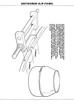
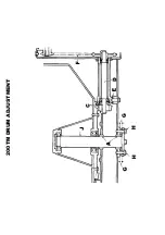
Page 12: ...200TM DRUM ADJUSTMENT...
Page 42: ...WORKSHOP MANUAL 200TM SECTION 3 GENERAL ARRANGEMENT DIMENSIONS...
Page 43: ...GENERAL ARRANGEMENT...
Page 44: ...DIMENSIONS...
Page 45: ...WORKSHOP MANUAL 200TM SECTION 4 SERVICE SCHEDULES LUBRICATION DIAGRAM...
Page 48: ...LUBRICATION POINTS...
Page 49: ...LUBRICANTS...
Page 50: ...WORKSHOP MANUAL 200TM SECTION 5 HYDRAULIC CIRCUIT DIAGRAMS...
Page 51: ...200TM LATER BASIC HYDRAULIC CIRCUIT...
Page 52: ...200TM LATER DRAGLINE BATCHWEIGER HYDRAULIC CIRCUIT...
Page 53: ...WORKSHOP MANUAL 200TM SECTION 6 WIRING DIAGRAMS...
Page 59: ...Hourmeter lamp dwg 04 03 02 12 50 36 Scaled to fit...
Page 60: ...Hourmeter no lamp dwg 04 03 02 12 53 33 Scaled to fit...
Page 62: ...WORKSHOP MANUAL 200TM SECTION 7 NOISE LEVELS...
Page 64: ...WORKSHOP MANUAL 200TM SECTION 8 SPECIAL TOOLS...
Page 65: ...200TM PUNCH VALVE SEAT 200TM SPECIAL TOOL V2003698 CASE HARDEN TO 45 50 ROCKWELL...
Page 66: ...200TM DRUM BLADE DRILLING GUIDE SPECIAL TOOL 200TM 513360100...
Page 67: ...200TM SPECIAL TOOLS...
Page 68: ...1 513204000 CLAMP DRUM CLIP 1 2 V2003698 PUNCH BLEED VALVE SEAT 1 200TM SPECIAL TOOLS...
Page 69: ...WORKSHOP MANUAL 200TM SECTION 9 HYDRAULIC CONTROL VALVE SERVICE MANUAL...
Page 70: ...PAGE INTENTIONALLY BLANK...
Page 71: ...WORKSHOP MANUAL 200TM SECTION 10 PARTS LISTINGS...
Page 73: ...200TM MAINFRAME AXLES AND STABILISERS...
Page 90: ...200TM 415 VOLT START STOP SWITCH STAR DELTA...
Page 92: ...200TM 415 VOLT START STOP SWITCH DIRECT ON LINE...
Page 98: ...200TM HOPPER...
Page 110: ...200TM WATER TANK FIT SPECIAL WASHER V2004220 BETWEEN ITEMS 11 12...
Page 114: ...200TM DYNAMO AND MOUNTING LISTER PETTER TS1 HS...
Page 118: ...200TM DRAGLINE ASSEMBLY...
Page 120: ...200TM DRAGLINE ASSEMBLY...
Page 124: ...200TM DRAGLINE SHOVEL...
Page 126: ...200TM DRAGLINE FEEDAPRON...
Page 130: ...200TM LISTER PETTER TS1 ELECTRIC START...
Page 132: ...200TM DECALS AND LOGOS 1 2 3 4 5 6 7 8 9 10 11 12 13 14 15 16 17 18 19 20 21 22...
Page 134: ...200TM DECALS AND LOGOS 23 24 25 26 27 28 29...
Page 135: ...200TM SPECIAL TOOLS...
Page 136: ...1 513204000 CLAMP DRUM CLIP 1 2 V2003698 PUNCH BLEED VALVE SEAT 1 200TM SPECIAL TOOLS...
Page 137: ...WORKSHOP MANUAL 200TM SECTION 11 BATCHWEIGHER MAINTENANCE INSTRUCTIONS...
Page 138: ...MAINTENANCE INSTRUCTIONS HYDRAULIC WEIGHING UNITS WWW WINGET CO UK...
Page 140: ......
Page 141: ......
Page 142: ......
Page 143: ......
Page 144: ......
Page 145: ......
Page 146: ......
Page 147: ......

