background image


AETA AUDIO SYSTEMS 

18-22, avenue Edouard Herriot – Kepler 4 – 92350 Le Plessis Robinson – FRANCE 

Tél. +33 1 41 36 12 00 – Fax +33 1 41 36 12 69 – Web: 

http://www.aeta-audio.com


55 000 061 - I 

4MinX - User manual 


Specifications subject to change 

– All rights reserved by AAS 

January 14 

55000061I_4MinX_en.docx
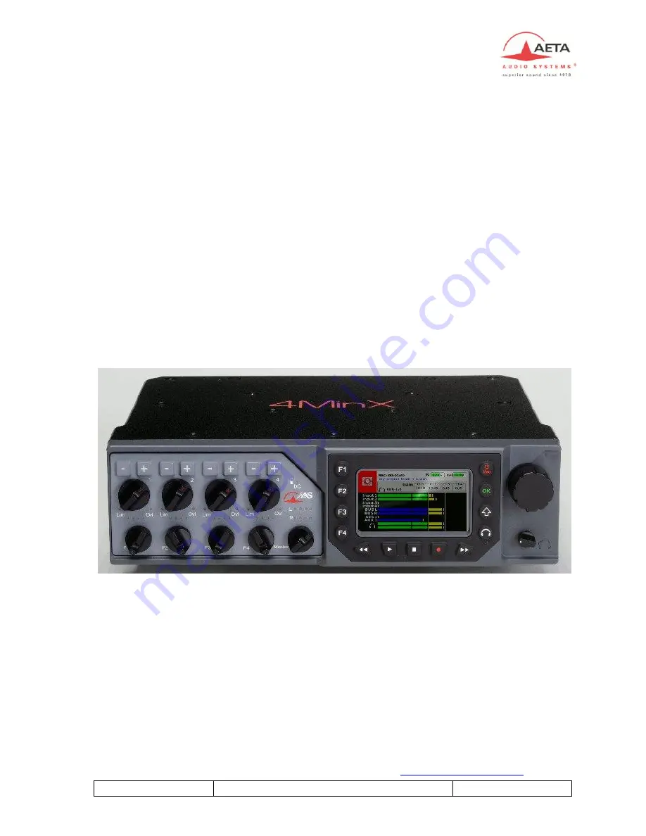
 

4MinX 

Portable Mixer/Recorder  


User manual


Summary of Contents for 4MinX

Page 1: ...Le Plessis Robinson FRANCE Tél 33 1 41 36 12 00 Fax 33 1 41 36 12 69 Web http www aeta audio com 55 000 061 I 4MinX User manual Specifications subject to change All rights reserved by AAS January 14 55000061I_4MinX_en docx 4MinX Portable Mixer Recorder User manual ...

Page 2: ......

Page 3: ...outputs 8 2 3 Monitor 9 2 3 1 Display screen 9 2 3 2 Configuration 10 2 3 3 Headphone monitoring 12 2 4 Internal alignment signal generator 12 2 5 Intercom Slate microphone 13 3 Powering 14 3 1 Specifications 14 3 1 Switching on and off 15 4 Menu description 16 4 1 General principles 16 4 2 Menu structure 17 4 3 Menu Audio 19 4 3 1 Menu Audio Inputs 19 4 3 2 Menu Audio Output 20 4 3 3 Menu Couplin...

Page 4: ... 5 4 Menu Function keys 37 4 6 Menu Tools 38 4 6 1 Menu Power down 38 4 6 2 Menu Sleep 38 4 6 3 Menu Eject media 38 4 6 4 Menu Reset settings 39 4 6 5 Menu Import export configurations 39 4 6 1 Menu Format media 39 4 6 2 Warning 40 4 6 3 Update 40 5 Operating mode Detailed description 41 5 1 Interface 41 5 2 Start a record 42 5 3 Play a take 43 5 3 1 Navigation 43 5 3 2 Play 43 5 3 3 Monitoring 44...

Page 5: ... 1 Microphone Line inputs 64 7 2 Line input 65 7 3 AES inputs 65 7 4 Line Out balanced analog outputs 66 7 5 Line Out unbalanced analog outputs 67 7 6 Digial outputs 67 7 7 Headphone output 68 7 8 Direct I O interface 68 7 9 EXT I O Interface for RF transmitters receivers 69 7 10 Power supply 70 7 1 Time Code 70 7 2 Dimensions and weight 72 7 3 Environmental 72 7 4 Options Hirose 10Pins 73 8 Annex...

Page 6: ...4MinX User manual 55 000 061 I 8 6 Limiter 83 8 7 Accessories 84 9 Notes 88 Index 89 Revision I Build on firmware V1 7 4 ...

Page 7: ... 10v phantom power 4Minx has many outputs 6 analog channels and 6 digital channels AES3 The routing capability for each input and each output give complete liberty to the user The multi tracks recorder can grow up to 8 tracks on SD SDHC card and can make a backup on external USB disk You should use SD SDHC card Class 10 or similar to avoid problems A project management included in the unit gives t...

Page 8: ...eo or M S coupling on inputs 1 2 et 3 4 Stereo M S encoder decoder on inputs 1 2 3 4 4 main line outputs maximum level adjustable from 9dBu to 22dBu 2 return or auxiliary line inputs maximum acceptable level adjustable from 9dBu to 22dBu for 0dBFS separate Stereo M S encoders decoders for monitoring 2 unbalanced outputs level 6 dB below the balanced outputs 3 QVGA TFT screen with adjustable bright...

Page 9: ...lanced Each input support 48V phantom power or T12 power If no powering is active unbalancing an input has no negative impact on the performance Each input has its own volume control on the front panel generally named fader Specificities Inputs 3 and 4 can also be fed from the EXT I O socket in which case no microphone powering is available Input 1 and 2 can stand very strong audio levels thanks t...

Page 10: ...e enabling in the same time as the digital filtering In this case rate will be 32dB Oct below 50Hz A limiter can be inserted into each channel post fader Its activation is shown by a green LED that turns red when the signal begins to limit Stereo and M S Via menu selection channels 1 and 2 3 and 4 can be used as independent channels or coupled for stereo or M S operation When used as a couple of s...

Page 11: ...s reserved L R Manual routing is inhibited and the signals are routed and decoded as follows Input impair is the M signal input pair is the S signal Input impair Input pair M S is routed to the Left bus Input impair Input pair M S is routed to the Right bus Limiters A limiter can be inserted into each channel after the channel fader This is a fast limiter with a dynamic range wide enough to stand ...

Page 12: ... case we provide you 15dB more gain Theses inputs have digital high pas filtering 50 Hz to 200Hz 12dB octave and 300 Hz 6dB octave suitable for compensating proximity effects in directional microphones 2 1 3 Embase EXT I O Récepteurs HF The EXT I O socket is available for the connection of an optional extension box This device can be used to interface 4MINX with radio transmitters and or receivers...

Page 13: ... effects in directional microphones 2 2 Audio outputs 2 2 1 Main outputs Line Out 4Minx have 2 stereo line outputs on XLR 5 pins By menu you can set source for each channels between all inputs bus monitoring The signals are electronically balanced they can be unbalanced with no impact on performance as long as the level stays below 19dBu The maximum output level which corresponds to the maximum di...

Page 14: ...suitable adaptation to most radio transmitters These outputs are asymmetrical 2 2 4 Digital outputs 4MINX delivers 24 bit stereo digital outputs it is possible via the menu to select either a Pro mode or Consumer mode depending on the type of equipment the signals are fed to A balanced and transformer isolated AES output 110Ohm impedance is available on the Dig Out socket It is possible to connect...

Page 15: ...st over them the level of the four microphone inputs in post and pre fader are shown Levels are displayed on large scale bargraphs covering 50dBFS to 0dBFS By menu you can set 4 metering level threshold Minimum nominal yellow red They are measured with fast PPM ballistics In addition peaks are held on for about 4 second peak hold function An OVL icon shows up whenever the level reaches 3dBFS or mo...

Page 16: ...wing signal sources for monitoring Input 1 to 4 in post or in pre fader Channel couple AES 1 2 AES 3 4 Return Line In couple of signals Bus Note The selection can be affected on one of function key F1 to F4 by a press on it A second bank is available by pressing the Shift You have a total of 8 monitoring presets Note When presets are available you should press twice the monitoring key to access to...

Page 17: ...55 000 061 I 4MinX User manual 11 To set a shortcut key you have just to press it under this display The current selected source and mode will be saving on this shortcut key Example Set preset F1 ...

Page 18: ...ed for example to listen a conventional stereo signal L R when monitoring M S microphones or when monitoring outputs that have been M S encoded Alternatively when the mixer is operated in normal stereo mode encoding the signals for monitoring can be used to check the stereo correlation by comparing the relative amplitude of the M and S signals 2 4 Internal alignment signal generator An integrated ...

Page 19: ... microphone A microphone is integrated in 4MINX s front panel its amplified signal can be inserted into the analog digital outputs replacing the normal audio signals See audio routing Slate A function key can be set to have a direct access to the feature ...

Page 20: ... power source 4MINX switches automatically between its internal battery and the external source without any noise priority is given to the external source when it is available The low battery level can be adjusted by menu from 6 9v to 7 3v When this threshold is reached a warning message is display on the screen and the battery icon is set in red Whenever the battery voltage goes down to 6 9 V 4MI...

Page 21: ...pplication start To switch off the unit you can go in the menu tools and select power down Or you can press Esc during 2s and press F1 to confirm Like that you will preserve the integrity of the systems and limits the risks to have defective audio files Note It is possible to switch off the unit by holding down the Esc button for more than 10 seconds This should be use only for emergy used ...

Page 22: ...on or push down the rotary Change the selected item or value using the rotary and press again the OK button to confirm the change Press the Shift button to leave a menu from one level Press the Esc button to leave a menu repeat the press to return to the normal meter screen In some case F1 to F4 keys can be used as function key On the main menu level many quick accesses are defined They give you a...

Page 23: ...mixing P1 P4 P1 to P4 potentiometers function Master Master gain level Mixdown limiter Limiter Compressor configuration Recordings Project management To create delete and modifie a project File management Configuration of recorded files Filename template template of recorded files Meta Data Management and entry of medata for BWF files Backup to USB Enable the backup of the current working day on a...

Page 24: ...ories Display settings Configuration of bargraphs and brightness adjustment Function keys Assign feature on assignable F1 to F4 key Recording BIP Enable disable BIP on record start and stop Date To change the system date Time To change the system hour Keyboard auto lock Automatic lock of the and keys after 10s USB keyboard keyboard language selection Tools Power down to switch off the unit Sleep t...

Page 25: ... at 50Hz 18dB Octave can be enable o Digital filter at 50Hz to 200Hz 18dB Octave and 30Hz 6dB Octave can be enable o A limiter can be enable o A 48Volts phantom power can be enable or a Tonader 12V o The phases can be inverted o Specific settings for microphone input 1 and 2 An 20dB attenuator PAD can be enable o Specific settings for microphone input 3 and 4 The input connectors can be switch fro...

Page 26: ...e maximum output level can be set between 9dBu to 22dBu o A 40dB attenuator can be added For each Extended outputs on I O connector MiniCon o The maximum output level can be set between 20dBu to 10dBu o AES out mode AES format Pro or Consumer 4 3 3 Menu Coupling In this menu you can select microphone coupling between o For 2 inputs Stereo or M S coupling on inputs 1 2 or 3 4 o For 3 inputs Double ...

Page 27: ...ster has no effect on the auxiliary bus An automatic attenuation is made depending of the number of selected sources Number of channels mixed into AUX bus Attenuation 1 0dB 2 6 6dB 3 10dB 4 12dB 5 6 14 4dB More 17dB Output sources For each analog and digital output you can select one of any inputs mixing bus monitor or play back sources Slate Last point you can specify on witch outputs the slate w...

Page 28: ...n configure a gain adjustment on the input line 1 2 both can be coupled on a single potentiometer or separated on 2 potentiometers The line input accepts a maximum level of 24dBu and gain adjustment covers a range of 15dB to 90dB 3 You can configure a gain adjustment on the AES input 1 2 or 3 4 Each couple can be coupled on a single potentiometer or separated on 2 potentiometers The gain adjustmen...

Page 29: ...xample Mic line1 2 coupling Channels 1 to 4 control mic line 1 to 4 inputs channels 5 6 control line inputs and finally channels 7 8 control AES 1 2 inputs For each channel you disposed of two actuators a linear fader and a rotary encoder The encoder is primarily to adjust the input sensitivity For more information on management see chapter management couplings ...

Page 30: ...compressor on the mixdown The user can adjust many parameters At first you should set the limiter threshold Adjustable from 2dBFS to 20dbFS after that the compressor threshold adjustable from 40dBFS to the limiter threshold and last parameter the compression of the compressor Disable to 1 6 To simplify the configuration we have defined 3 profiles for the reactivity of the limiter compressor Slow n...

Page 31: ...validation of a project is necessary to enable it The validation is done through the function F4 key 1 Project management This module allows to create a new project the work day will be the day of the machine date system You can destroy a project But to destroy the current project it is necessary to select another project before Only information related to the project is destroyed but not audio fi...

Page 32: ...rom canvas 2 Workday management This module allows creating a new work day with the date system You can destroy a workday WARNING Only AUDIO files of this day will be destroyed we keep all takes information It is the only way to destroy audio files Can generate a report of the day s work in HTML and CSV format on SD card via the Sound report menu ...

Page 33: ...arious fields The Esc key cancels any changes 4 4 2 Menu File Management In this menu you can configure your records This configuration is linked to the active project We work by file Each file can be either Mono or well polyphonic several mono tracks in the same file In case of use coupling microphone you can specify Stereo M S Double M S A or B format Option soundfield e You should respect the t...

Page 34: ...t the post product can identify easily what microphone was used The files are WAV files with the extension BWF and iXML fields This type of file remaining fully compatible with a standard WAV file For each file you can select the sources The number of selectable sources depends on the number of tracks authorized on your machine see About menu To create or destroy files you have at your disposal th...

Page 35: ...pe You can change all or only one source You should use the rotary do go on the field whose be modify displayed in red To validate source s of the selected file you should press F4 or SHIFT Or press Esc to cancel modification If the file is not valide you have a in the sources field ...

Page 36: ...sposal 3 fields For each field you can select between the project name Scene name Working day Recording type Canvas The file will have the following name Field 1 _ Field 2 _ Field 3 scene index _ Take index _ File number Split file index wav Note the Split file index is the index of the 2Go file split FAT limitation size 4 4 4 Menu Meta data ...

Page 37: ...n external USB keyboard 4MinX support every kind of USB keyboard wire or wireless You can specify in the 4MinX 3 keyboard types UK French and German Some specifics characters aren t take in care to stay compatible with the FAT system file Use the virtual keyboard o The letter selection is made via the encoder o The validation of the letter is made via the OK button o The position of the cursor can...

Page 38: ... of the record via the menu Recording type This information can be used in the name of the file You have the choice between Wild Sound Pick up Announce Time Sync Not specify Ignore Canvas For people working with 3 indexes a canvas is available in this menu too The canvas has the following format sequence number letter scene take The canvas is automatically incremented at each new take and it is re...

Page 39: ...d can be read form the audio file in post production to identify easily sources These labels are save in the snapshots 4 4 5 Menu File format You can specify the number of bits of the BWF file 16 bit or 24 bit files in this menu 4 4 6 Menu Pre record 4minX supports up to 10s of pre record based on the number of tracks and sampling frequency Pre record is automatic reset on each configuration chang...

Page 40: ... external hard drive on the USB port you have the opportunity to make a backup of audio files of the current day The transfer is done in background You can stop the transfer and resume at a later date where you are At any time you can check the backup statue via this menu The State of the backup is shown by icon in the main window instead of the external USB drive icon Symbol red round backup runn...

Page 41: ...nu Synchronization In the Mode menu you can choose the mode Master operation on the internal clock or select an external sync mode AES or a word clock Time code Option In the Frequency menu you can select the sampling rate frequency from 32kHz to 96 kHz Note It is imperative to select same sampling rate as the external source of synchronization for the proper functioning of the machine ...

Page 42: ... 29 97 drop or 30 drop frames per second Set Time Code menu specify its value for the free run mode or when 4MinX is used as a generator of time code You can reset it to 0h 0m 0s use the current hour or set it as you want An adaptation of LEMO5points to two sheets BNC cable is available as an option Led bicolor on the right side of the 4minX gives you the State of the Time Code module configuratio...

Page 43: ...levels on the screen between VU mode and dBFS mode In VU mode the 0dB level corresponds to the threshold of the yellow led The Bargraph count menu allows you to benefit of 4 additional bargaphs in mode full 4 Additional bargraphs are blue instead of green The Bargraph display menu allows you to select between 2 mode the bargraphs sources The Tracks mode follow file tracks configuration and teh Use...

Page 44: ...6 2 Menu Sleep This menu allows putting the 4Minx in standby In standby the consumption is reduced to 1 5W All microphones power are cut and the 9V for the wireless transceivers and receiver is turn off By pressing Esc key you return to the normal operating mode in 3s You can press during 1s the ESC key in place to use this menu too and confirm by F1 Note The backup job will continue in this mode ...

Page 45: ...ing on the unit we import only new takes information Other project settings are kept like file configuration meta data Note no projects are deleted when you make an import Settings A reboot of the machine is necessary after importing a configuration Debug Via the export menu debug you can retrieve all the information relevant to analyze problems on the SD card directory 4 6 1 Menu Format media Thr...

Page 46: ...e disk will be lost 4 6 2 Warning You have 3 sub menu to set warning threshold Warning threshold for the NP F battery the minimum value is 6 4V Warning threshold for the external DC power Warning threshold for remaining SD card disk space 4 6 3 Update Check on the SD card an update file and launch the update if it is found ...

Page 47: ...e first line and in the second function accessible with the shift key 4 Synchronization and sample rate frequency indication 5 Time Code or system hour 6 Last recorded scene and take index 7 Project name and work day 8 USB disk icon and USB keyboard icon 9 SD SFHC card information 10 Files tracks status 11 4 mic line configuration status for the selection function key ie microphone Chx change to b...

Page 48: ... with there s configuration armed in red or not armed in green If you press OK you can see the USER configuration bargraphs You can switch at any time between this screen and the standby screen by pressing the encoder or the OK button On this screen you can see the true name of file for your next record The function keys are still here They appear on first press and become active You should press ...

Page 49: ...een 5 3 1 Navigation You can browse between take in the current scene via the F1 and F2 function keys You can see on the display the current reading position and the total duration or final Time code of the file The progress bar allows you to follow the temporal evolution of reading To coming back in record you get out of the reading module via the F4 key 5 3 2 Play To start reading you should pre...

Page 50: ...de The player has its own monitoring configuration It doesn t affect the recorder monitoring configuration 5 3 4 Search or modify a take If you want to replay another day of work and another project file you can select it via the accessible menu by the F3 key It was under this module that you can mark the take as good or reset this tag via the button Set Circled You can also change note linked to ...

Page 51: ...ng a global vision of the current configuration of your 4Minx you have 4 screens where you can modify settings Theses screens are available at the root menu on F1 to F4 keys All screens have the same management concept It is base on table where line can be selected by the rotary encoder The selected line is set in red Settings of this line can be set by and keys from channel 1 to 4 You can have up...

Page 52: ...u should turn the encoder to see Gain in red To change gain of the input x you should press or key of the channel x F2 line input configuration With channel 1 keys you can change Line 1 setting and with channel 2 setting of Line 2 To speed of the selection a combo list appears and the selection should be made with the encoder ...

Page 53: ...st settings 5 5 2 Audio Routing With this screen you can set mixed bus configuration Channel 1 keys change the selected input routing in the MIXDOWN bus The Channel 2 keys change the selected input routing in the AUXILIARY Bus An X indicate routing configuration of this input in this BUS If you have enable pan pot function you can select it with P configuration ...

Page 54: ...nt value and the stored value try to match them 5 6 Snapshots A snapshot is a picture of the current configuration It is an easy tool to save a working space quickly A snapshot is backup of the current audio configuration it save microphone choices and audio output configurations If you should coming back or you use frequently same microphone configuration you don t need to set manually all settin...

Page 55: ...st or reused one entry To identify easily a snapshot you can name it through edition interface To modify it later you should load it and save it again on the same memory To speed of the configuration load you can assign snapshots to function keys You have also a shortcut on F1 in the main menu when you select Settings 5 6 2 Export You can export a selected snapshot or all snapshots on the SDCARD E...

Page 56: ...D 5 6 3 Import When you choice to import snapshots from your SDCARD we show you all snapshots found on it under a list you should select the wanted snapshot in the list and select after the place where you want to have it Ex load the double_ms1 3 snapshot in the memory 6 ...

Page 57: ...rovide details on compatible microphones with the 4minX We don t speak about configuration needed more than 4 microphone inputs 6 1 1 Monophonic Monophonic microphones are the base You can found different capsule on the market Except their power they are managed under the same way on the 4Minx You should disable coupling on its input you can manage its own gain and apply treatment on it After that...

Page 58: ...ere you have a figure eight bidirectional for the Side Coupling stereo should be set Spaciousness limited but good localization Coupling M S should be set to decode it in stereo A M S decoder can be also enable on the monitoring Spaciousness limited but good localization Coupling stereo should be set Spaciousness sastisfactory and good localization Coupling stereo should be set Spaciousness good b...

Page 59: ...ng Double M S should be selected With 4 microphones inputs Side split on 2 inputs Coupling M S on 1 2 and 3 4 SPS200 A format Soundfield coupling should be selected for having A format to stereo decoder The decoder has effect only on the monitoring B Format coupling should be selected for having B format to stereo decoder The decoder has effect only on the monitoring Double M S M S M Front X Heigh...

Page 60: ...00 061 I IRT cross Link All 1 2 3 4 coupling should be enable It can be monitoring one by one capsule on the 4MinX Hamasaki square Link All 1 2 3 4 coupling should be enable It can be monitoring one by one capsule on the 4MinX ...

Page 61: ...oupling In case of stereo coupling on input 1 2 and 3 3 on the 4MinX you have Input 1 Left Input 2 Right Input 3 Left Input 4 right On the 4MinX On a surface control Common microphonegain Stereo width Fader Common microphonegain Stereo width Fader ...

Page 62: ...In case of M S coupling on input 1 2 and 3 3 on the 4MinX you have Input 1 Middle Input 2 Side Input 3 Middle Input 4 Side On the 4MinX On a surface control Middle gain Sidegain Fader M S Angle adjustment Middle gain Sidegain Fader M S Angle adjustment ...

Page 63: ...put 1 2 3 on the 4MinX you have Input 1 Front Middle Input 2 Side Input 3 Rear Middle On the 4MinX On a surface control Middle gain Front Sidegain Fader Front M S Angle adjustment Middle gain Rear Fader Rear Middle gain front Sidegain Fader front M S Angle adjustment Middle gain rear Fader rear ...

Page 64: ...ddle rear gain is a 6dB balance from middle front gain In this mode only the front M S is decoded in the mixdown The 4MinX will give you a separated monitoring for the front and for the rear Note The Double M S microphone is mixed as 2 separated M S microphones in the mix down after stereo conversion ...

Page 65: ... Link all 1 to 4 In case of Link all 1 on input 1 2 3 4 on the 4MinX you have On the 4MinX On a surface control Separated gain but filters limiter are linked together Common Fader for input1 to 4 Separated gain Common Fader for input1 to 4 ...

Page 66: ...Left Front Input 2 RF Right Front Input 3 LB Left Back Input 4 RB Right Back B Format microphone Input 1 W sound pressure Input 2 X forward backward Input 3 Y left right Input 4 Z upward downward Microphones Management On the 4MinX Gain filters limiter are linked together Common Fader for input1 to 4 ...

Page 67: ... use a dedicated monitoring to decode the A or B format You can turn around the microphone by 45 step With this monitoring you have the best monitoring as possible during your records Specific monitoring for the SOUNDFIELD A format Microphone SPS200 Gain commun VolumeCommun aux 4 entrées ...

Page 68: ...62 4MinX User manual 55 000 061 I Specific monitoring for the B format L R ML SR SL S C MR ...

Page 69: ... B format microphones you should indicate in the Audio Channel coupling menu the orientation of the microphone for the SPS200 and the stereo width between 60 and 180 For the SPS200 A format from SoundField For the B format Orientation choice for the SP200 microphone Format A ...

Page 70: ... 48 V Tonader T12 V Maximum input level with Pad on input 1 and 2 39 dBu Maximum input level input 3 4 19 dBu Input headroom 40 dB Input stage gain menu setting 0 to 50 dB 10 dB steps Equivalent input noise EIN Gin 50 dB 128 dBu 200 22 Hz 22 kHz Maximum gain analog in to out 90 dB Bandwidth 10 Hz 50 kHz 0 dB 1 dB Common Mode Rejection 90 dB 1 kHz Mic Input impedance 2 k Line Input impedance 10k ...

Page 71: ... pin XLR 1 Ground 2 Line 1 3 Line 1 4 Line 2 5 Line 2 Maximum input level 24 dBu Bandwith 10 Hz 50 kHz 0 dB 1 dB Commun mode rejection 90 dB 1 kHz Input Impedance 10k 7 3 AES inputs Number 3 Format AES 3 Socket XLR male 3 pin Switchcraft Digital microphone powering mode Phantom 10 V 250mA by socket AES 42 normalization ...

Page 72: ...3 4 Line 2 4 5 Line 2 4 Output attenuators Pad 40 dB balanced separate for L and R Maximum output level 0 dBFS Adjustable via menu 9 dBu to 22 dBu Source impedance 100 Output balance 40 dB 20Hz 20 kHz Accuracy 60 dB 20Hz 20 kHz Channel isolation 90 dB 22Hz 22 kHz Signal Noise Ratio 80 dB soit THD N 0 01 SINAD Signal to Noise and Distortion Ratio 40 dB 20Hz 20 kHz ...

Page 73: ...t level 6dB below balanced output Maximum output level 16 dBu Source impedance 100 7 6 Digial outputs 3 mini XLR TA3 provide 2 digital channels 3 times The pin allocation of the TA3 socket is as follows The outputs levels have an AES level 4Vc c110 The SPDIF adaptor cable See Annex Accessory make audio level adaptation to have these characteristic Pin Function 1 Ground 2 Output 3 Output ...

Page 74: ...adphone output Socket Jack 6 35mm stereo Maximum output level 20 dBu Acceptable output load 16 7 8 Direct I O interface Pinout of the subD 9 pins Pin Function 1 Pre microphone amplifier channel 1 2 Pre microphone amplifier channel 3 3 Ground 4 Contact 5 power 2 5v 6 Pre microphone amplifier channel 2 7 Pre microphone amplifier channel 4 8 Ground 9 Command input 0V 2 5V ...

Page 75: ...rce impedance 1 k The pin allocation of the EXT I O socket is as follows Pin Function Direction 1 L signal to RF transmitter Output 2 Not used 3 Analog signal ground 4 Analog signal ground 5 R signal to RF transmitter Output 6 Input 4bis Input 7 Input 4bis Input 8 9V output Output 9 Input 3bis Input 10 Analog signal ground 11 Input 3bis Input 12 Input Cable connector reference NEUTRIK MINICON MRM ...

Page 76: ...t Hirose 4 has following pin allocation Pin Function 1 Ground 2 3 External DC for the internal battery charger 4 4Minx external DC input Cable connector reference HIROSE HR10A 7P 4P 73 7 1 Time Code Pin out of the serial 0B LEMO 5 pins connector EXG 0B305 HLN Cable connector reference LEMO FGG0B305CLAD52 Pin Function Direction 1 Ground 2 LTC camera output Input 3 ASCII Input output 4 Tuning Output...

Page 77: ...55 000 061 I 4MinX User manual 71 ...

Page 78: ... 10 2 x3 0 x7 7 Weight 1900 g 7 3 Environmental 4MINX can operate from 20 C to 55 C ambient temperature 4 F to 131 F 4MINX complies with EC directives regarding safety EMC and hazardous substances RoHS Safety compliant with EN60950 Susceptibility compliant with EN50082 1 Emission compliant with EN55022 class B ...

Page 79: ...the 4 channels Upon request replacing the female base XLR5M outputs 3 4 4MinX can be equipped with a base 10 pins Hirose RM15TRD 10S for wire connection for Go Return unbalanced with a two channels analog recorder The entrance is style accessible on the XLR 5F 1 Left output 5 Right input 2 Left output 6 Right input 3 Right output 7 Left input 4 Right output 8 Left input 9 Ground 10 Ground ...

Page 80: ...e code In most case sound editor read at first the waf header and complete data base by the iXML part Here is list of managed field by the 4MinX Field Set by Description PROJECT User Project name SCENE User Scene index or Sequence Scene TAKE User Take index or Canvas take TAPE Auto Set to 1 FILE_UID Auto Set to AAS4MI 4minx serial number NOTE User Note on the take CIRCLED User Mark good take USER ...

Page 81: ...uto AAS 4MinX BWF_ORIGINATOR_REFERE NCE Auto AAS BWF_ORIGINATION_DATE Auto System date BWF_ORIGINATION_TIME Auto System hour BWF_TIME_REFERENCE_LO W Auto Time code information BWF_TIME_REFERENCE_HIG H Auto Time code information BWF_DESCRIPTION Auto Same as waf header project scene take information TRACK_COUNT Auto Number of track in the file CHANNEL_INDEX Auto Track number in the file INTERLEAVE_I...

Page 82: ... gain 9 Monitoring menu access 3 Panpot or other feature 10 Display 4 Channel adjustment status 11 On Off Escape key and OK key 5 Master gain bus level L R 12 Rotary interface 6 External DC Charge LED 13 Headphone volume control 7 Function keys 14 Slate microphone 8 Recording keypad 15 Shift key 4Minx s back panel 1 Battery socket 2 NP F Battery ...

Page 83: ...55 000 061 I 4MinX User manual 77 ...

Page 84: ...er 4 Digital outputs AES 3 TA3 Right panel 5 Stereo headphone output 6 Auxiliary stereo output unbalanced 7 Main Line outputs balanced 8 Line In Return inputs 9 Direct outputs from the 4 channel 10 External power input 11 Ethernet interface 12 SD SDHC CARD holster 13 USB host 14 Micro USB 2 0 OTG 15 Time Code input output Optionel 16 Word clock input Optionel ...

Page 85: ...55 000 061 I 4MinX User manual 79 8 3 Block diagram ...

Page 86: ...ost 2 M S L R C PanPot Outpre1 14 4 100 to 20dB Coupling Stereo MS Coupling Stereo MS Balance or S width Balance or S width 100 to 20dB Mixdown BUS L R C L R C Auxiliary AUX 6 24dB 1dB steps L R C L R C L R C Master 90 36dB 90 36dB 90 0dB Slate Tone 40dB PAD 6 35mm Line out 3 4 Line out 1 2 3 5mm Ext I O I O 1 I O 2 AES 1 2 SubD 9pts Out Pre4 Out Pre3 Out Pre1 Out Pre2 40dB PAD AES 3 4 AES 5 6 Rou...

Page 87: ...55 000 061 I 4MinX User manual 81 8 4 Level maps ...

Page 88: ...Green 50Hz 12dB Oct Digital Red 80Hz 12dB Oct Digital Pink 120Hz 12dB Oct Digital Dark blue 160Hz 12dB Oct Digital Cyan 200Hz 12dB Oct Digital Green 300Hz 6dB Oct Digital 40 0 38 36 34 32 30 28 26 24 22 20 18 16 14 12 10 8 6 4 2 d B r 20 1k 30 40 50 60 70 80 90 200 300 400 500 600 700 H z ...

Page 89: ...55 000 061 I 4MinX User manual 83 8 6 Limiter Black No limitor Blue Threshold set to 6dBFs Green Threshold set to 8dBFs 24 2 22 20 18 16 14 12 10 8 6 4 2 0 d B r 40 15 35 30 25 20 15 10 5 0 5 10 dB u ...

Page 90: ...84 4MinX User manual 55 000 061 I 8 7 Accessories Many accessories are available including Power supply AC DCconvertor NPF 960 Battery ...

Page 91: ...55 000 061 I 4MinX User manual 85 NP1 holdster for NP1 battery Car adaptor power cable Adaptor cable XLR5 to 2 XLR3 for line outputs ...

Page 92: ...86 4MinX User manual 55 000 061 I Adaptor cable from 2 XLR3 to XLR5 for line inputs AES adaptor cable from TA3 to XLR3 Specific adaptor cable for wireless microphone receiver and transmitter ...

Page 93: ...7 Compact keyboard QZERTY Micro A or Micro B cable adaptor to HOST A interface Carring Bag Other on request Adaptor cable for AES output to SPDIF on RCA Adaptor Time code cable between Lemo 5 and 2 BNC connectors MiniCon 12pins alone ...

Page 94: ... ____________________________________________________________ ____________________________________________________________ ___________________________________________________________ ____________________________________________________________ ____________________________________________________________ ____________________________________________________________ __________________________________...

Page 95: ...ters 81 Format A 28 53 61 Format B 28 53 62 Function keys 37 H Hamasaki square 54 Hirose 10Pins 72 I Interface 41 IRT cross 54 L Level maps 80 Li Ion DV battery 14 Limiter 5 82 Limiter Mixdown 24 Link all 59 Lock 48 M M S 27 52 56 Meta data 30 Meta Data iXML 28 73 MIDI 22 Mixdown 21 Monitoring 9 N Note 32 44 NPF 9x0 14 O ORTF 52 P P1 P4 function 22 Panels 75 78 Player 43 Pre record 33 Project 24 R...

Page 96: ...Shortcuts 45 Slate 13 21 Snapshots 48 Snapshots 37 Sound report 25 26 Soundfield 60 Sources names 33 SPS200 53 61 Stereo 27 52 55 T Time Code 36 70 Tone 12 37 W Workday 26 ...

Page 97: ... 2012 AETA AUDIO SYSTEMS www aeta audio com ...

Reviews: