WF-10T
Case Former
Case Size Adjustments
7-57
7.9
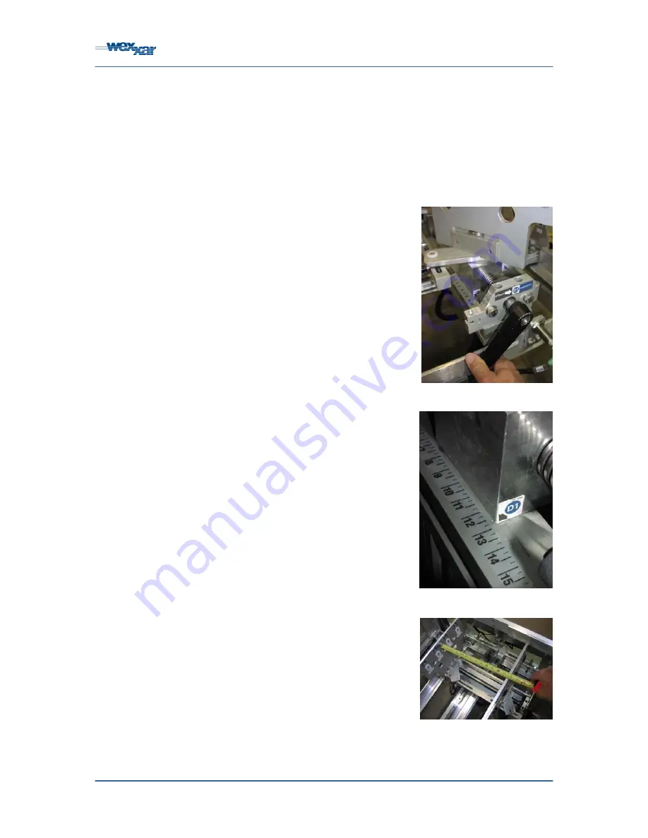
Jawplate Case Width Dimension ‘D1’ Adjustment
There are 3 machine adjustments affected by the width of the formed or erected case. The first is
‘D1’, the width between the carriage jawplates, which feature the pin and dome technology that is
used to grip the bottom flaps and open the unformed case blanks. The second formed case
width measurement is ‘D2’, which determines the position of the bottom ski that folds the leading
minor bottom flap as the erected case is pushed into the machine conveyor by the carriage. The
third formed case width dimension is ‘D3’, the width between the conveyor belts that drive the
case over the tape head and out of the machine.
Before making any machine adjustments, refer to the
shutdown procedure outlined in Section 6.5:
‘Shutdown’
.
On the scale provided, measure the formed case width
(Dimension ‘D’) at both ends of the case to determine if
there is any difference between the two measurements.
If the case is manufactured slightly off-center, this width
differential is sufficient to impact on Dimension ‘D1’ and
‘D3’ case width adjustments.
If one side of the case is even very slightly wider than the
other side, it is best to ensure that the wider side is
placed towards the infeed end of the machine. A slightly
wider case width in the back will permit the kicker arm
and finger to fold in the bottom rear minor flap without
any risk of the flap being obstructed by the perpendicular
extended major flaps. This prevents the rear major flap
from bending upwards during case forming. If
necessary, you can compensate for this problem by
adjusting Dimension ‘D1’ very slightly wider than the ‘D3’
adjustment.
To set Dimension ‘D1’, first press any
‘EMERGENCY
STOP’
button and open the operator’s side guard door
(or the guard door on the side where the Dimension ‘D1’
hand crank is located) to gain access to the Dimension
‘D1’ adjustment. The pneumatic pressure is now
removed from the carriage assembly, which should now
move freely along the linear carriage guide track.
Loosen each of the four quick-adjust handles that secure
the jawplate assembly to the carriage assembly. Two
handles are located on the front, and two on the rear of
the carriage. Now pivot the free-moving jawplates until
they are parallel with each other and in-line with the
linear carriage guide track.
Turn the Dimension ‘D1’ hand crank until the ‘D1’ pointer
approaches the measured formed case width. Then
open a case blank and position it on the jawplates such
that the pins engage the outside edges of the bottom
major flaps.
Figure 7-13: Dimension ‘D1’
Hand Crank
Figure 7-14: Dimension ‘D1’
Pointer
Figure 7-15: Measuring Parallel
Jawplate Width
Summary of Contents for WF-10T
Page 2: ...WF 10T Case Former ...
Page 118: ...WF30T Case Former Appendix A MSDS Geralyn FMG 387 106 ...
Page 119: ...WF30T Case Former Appendix A MSDS Geralyn FMG 387 107 ...
Page 120: ...WF30T Case Former Appendix A MSDS Geralyn FMG 387 108 ...
Page 121: ...WF30T Case Former Appendix A MSDS Geralyn FMG 387 109 ...
Page 122: ...WF30T Case Former Appendix A MSDS Geralyn FMG 387 110 ...
Page 123: ...WF30T Case Former Appendix A MSDS Geralyn FMG 387 111 ...
Page 125: ...WF 10T Case Former Appendix B Keystone Nevastane HT 2 113 ...
Page 126: ...WF 10T Case Former Appendix B Keystone Nevastane HT 2 114 ...
Page 127: ...WF 10T Case Former Appendix B Keystone Nevastane HT 2 115 ...
Page 128: ...WF 10T Case Former Appendix B Keystone Nevastane HT 2 116 ...
Page 129: ...WF 10T Case Former Appendix B Keystone Nevastane HT 2 117 ...


