


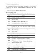
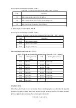


66
④ If digital tube pressure display decrease,then there is gas leakage inside gas console or
between gas console and switch valve;
⑤ If gas supply pressure down, then there is gas leakage between the gas supply valve and
gas console.
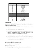
11.Preventive maintenance
Wearing parts working life become shorter is one of a early signs when the plasma system
got problems. It increases cost by two aspects: firstly, operator have to use more
consumables for same qty work-piece cutting, secondly operator has to stop more times to
replace the consumables.
Suitable maintenance can reduce the production cost obviously.
1)
Plasma power source
① Remove the side and top covers once a month, use dry compressed air to flow away
dust;
② Check the cutting machine cable regularly to check if any damages or wearings. If the
cable color fade,and caused by overheat, please replace it;
③ Check the contactor regularly, check the connection is corrosive or not, if the surface is
black and hard, please replace it.
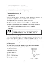
2)
Cooling system
① Replace the coolant and clean the coolant pipelines regularly (6 month or 300 arc
hours).The maintenance time based on actual working strength and environment.
How to clean the coolant pipelines:
Step 1:Refer to coolant discharge method and drain out all coolant in the pipelines.
Step 2:Fulfil pure water and let cooling system work 10 mins.
Step 3:Drain out the pure water and fulfil again with coolant.
② Check the coolant level, if short of coolant, add more;
③ Regularly check the coolant filter mesh under cutting machine front panel, clean and
replace if need;
④ Regularly check the pump filter mesh, clean and replace if need;
⑤ Power on the machine and keep it on standby status, check if any coolant leakage: the
inlet and outlet connectors on rear side of cutting machine, HF box torch connection parts,
water tube connection parts, and plasma torch;
Summary of Contents for FLG-200HD
Page 9: ...5 Figure 2 1 System connection diagram ...
Page 43: ...39 Figure 5 2 SQK A1 front panel function Figure 5 3 SQK B1 front panel function ...
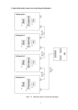
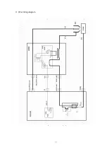
Page 74: ...70 4 System wiring diagram Figure 7 1 System wiring diagram ...
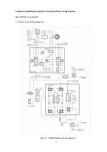
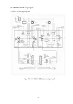
Page 77: ...73 2 Main circuit wiring diagram 2 Figure 7 4 FLG 200HD Main circuit wiring diagram 2 ...
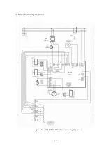
Page 81: ...77 6 HF striking diagram Figure 7 8 HF striking diagram ...


