


63
2)
Rotate the filter bowl and take it down, clear it.
3)
Take out the old filter elements and install a new one.
Note: please don’t rotate the filter elements when loosen bolts.
4)
Re-install the filter bowl carefully, in case of gas leakage.
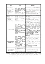
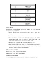
9. The maintenance of cooling system
1)
Coolant discharge
① Turn off the power switch of plasma power source,put the coolant back pipe (with red
tape) from rear panel of plasma power source,and put it into a 20L container.
② Press know “8” and wait 5 seconds, then the pump start working.
③ Let the pump working until there is no coolant discharge, then release Know “8”.
④ Connect the coolant back pipe (with red tape) back to machine panel, and screw up.
Note: Water pump may be damaged if long time running without load.
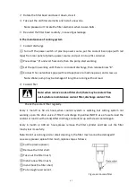
2)
Coolant filer
Note: when remove coolant filter shell,there maybe coolant flow
out.So,before maintenance coolant filter,discharge coolant first.
Check the coolant filter regularly.
Every 1 month or 50 arc hours,when coolant system is working but cutting system not
working, open the drain valve of filter to discharge impurities (NOTE: use a hose to lead the
coolant or load it with a tank).After discharge coolant,ful up with clean coolant again.
Every 6 month or 300 arc hours,please remove the filter cylinder and take out the filter
mesh,clear it carefully.
Note:Do not use strong acid or alkali cleaning it, the filter mesh cannot be damaged.If
necessary,please replace filter mesh,replace step as follows:
① Cut the plasma power;
② Remove the filter shell;
③ Take out the filter mesh;
④ Install a new filter mesh;
⑤ Install back the filter shell;
⑥ Put enough new coolant.
Figure 6-1 Coolant filter
Summary of Contents for FLG-200HD
Page 9: ...5 Figure 2 1 System connection diagram ...
Page 43: ...39 Figure 5 2 SQK A1 front panel function Figure 5 3 SQK B1 front panel function ...
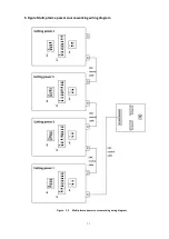
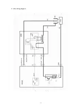
Page 74: ...70 4 System wiring diagram Figure 7 1 System wiring diagram ...
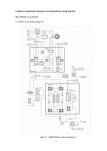
Page 77: ...73 2 Main circuit wiring diagram 2 Figure 7 4 FLG 200HD Main circuit wiring diagram 2 ...
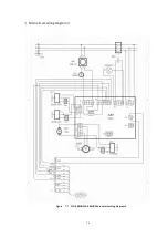
Page 81: ...77 6 HF striking diagram Figure 7 8 HF striking diagram ...


