


48
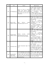
Output open circuit voltage
Make high frequency
The checked current of sensors TA102 and TA202, is equal to pilot arc current
6)
Transferred arc :
The checked current on work-piece cable
7)
Current up : cut flow.Current on work-piece cable rise to setting point, gas switch to
cutting flow.
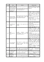
8)
Stable cutting: cut the work-piece with normal cutting parameter
Cooling liquid flow normal
Air pressure normal
Input voltage normal
No radiator temperature protection
No liquid overheat protection
9)
Current down: After turn off the arc striking signal, current on work-piece cable down
to setting point, gas pressure down
10)
Automatic cut off : After 10s
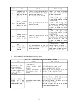
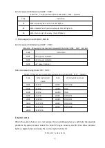
2. Gas blowing process
The system start blowing process automatically after power on or when operator switch the
gas process. Blow time is 24s, divided into 2 steps: Preflow gas blowing (12s) and Cutflow gas
blowing (12s).
There are two special situation on blow process: When operator switch gas process, switch
nonflammable gas (O2/Air,Air/Air,N2/Air) to flammable gas (H35/N2,F5/N2) or opposite,
blow process shall be divided to 3steps. Firstly blow gas supply system by N2 for 12s,
secondly blow by preflow gas and cutflow gas.
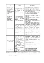
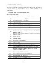
3. Gas console solenoid valve operation
If the gas pressure abnormal and gas console warning, if air supply pressure is normal, shall
check the solenoid valve of Gas console and HF box to see if it’s damaged. Or check if the
PL11 control board of gas console is damaged. LED indicator for solenoid valve and related
PL11 control board, under different cutting process, please check the below table.
Summary of Contents for FLG-200HD
Page 9: ...5 Figure 2 1 System connection diagram ...
Page 43: ...39 Figure 5 2 SQK A1 front panel function Figure 5 3 SQK B1 front panel function ...
Page 74: ...70 4 System wiring diagram Figure 7 1 System wiring diagram ...
Page 77: ...73 2 Main circuit wiring diagram 2 Figure 7 4 FLG 200HD Main circuit wiring diagram 2 ...
Page 81: ...77 6 HF striking diagram Figure 7 8 HF striking diagram ...


