


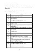


58
Code
Item
Details
Measurement
156
There is current on
deputy machine
have current after
power on
There is current output signal on
the sensor of TA202 of the deputy
machine when power on.
(No error code on FLG-200HD)
Current hall sensor or control
board PL01 damaged,contact
manufacture for help;
163
Plasma gas cutflow
pressure ±25%
over the set value
Plasma gas cutflow pressure ±25%
over the set value
1.Check
shield
gas
supply
pressure value whether in range
of 0.8MPa±10%;
2.Check if the voltage valve
regulator setting value of shield
gas is correct, or reset the
pressure according to cutting
chart;
164
Shield gas cutflow
pressure ±25%
over the set value
Shield gas cutflow pressure ±25%
over the set value
1.Check
shield
gas
supply
pressure value whether in range
of 0.8MPa±10%;
2.Check if the voltage valve
regulator setting value of shield
gas is correct, or reset the
pressure according to cutting
chart;
180
CAN
communication
overtime during
working
No communication is set up
between plasma machine and
manual gas console
1.Communication
cable
is
interfered,restart the system;
2.Check if the control cable from
power source to gas console is
damaged or well connected.
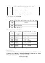
2)
Trouble shooting without displaying error code
Table 6-13 Trouble shooting without displaying error code
Item
Details
Measurement
.
Turn on the plasma
power source,all
indicators of power
source not light on,gas
console panel no
displaying.
1,Default phase;
2,Power
supply
switch
damaged;
3,Control transformer of
plasma power source
no
output;
1,Check three phase power supply;
2,Replace power source switch;
3,Replace 8A fuse on power source rear
panel, or change a new transformer;
Power
indicator
of
power
source
light
on,but
gas
console
panel no displaying.
Gas console power supply is
abnormal
1,Check if there is 110VAC voltage on gas
console rear panel XS2 connector;
2,Check if the output voltage of PCB PL10
of gas console is correct;
3,Check the input voltage of gas console
control board PL09 is correct;
Summary of Contents for FLG-200HD
Page 9: ...5 Figure 2 1 System connection diagram ...
Page 43: ...39 Figure 5 2 SQK A1 front panel function Figure 5 3 SQK B1 front panel function ...
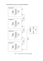
Page 74: ...70 4 System wiring diagram Figure 7 1 System wiring diagram ...
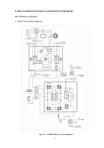
Page 77: ...73 2 Main circuit wiring diagram 2 Figure 7 4 FLG 200HD Main circuit wiring diagram 2 ...
Page 81: ...77 6 HF striking diagram Figure 7 8 HF striking diagram ...


