


52
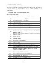
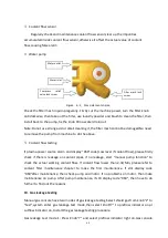
4. Trouble shooting and error code
1)
Error code and repairing
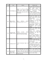
Table 6-12 Error code and repairing
Code
Item
Details
Measurement
000
No error warning
System got no error warning
No need to do anything
009
Flow switch testing
After pump time-out (No start
signal 30 Mins),and restart the
pump, cooling system start
working, if cooling liquid flow
lower than 2.3L/min, error warning
appears,if cooling liquid flow
higher than 2.3L/min, this error
disappear automatically. During
this error warning, keep the
cutting system under preflow
status, to make sure the cooling
liquid is normal before cutting. If
after cutting power source receive
start signal for 10s, the liquid flow
still lower than 2.3L/min, error
code will be replaced by “060”.
No need to do anything under
this code. And this code lasts no
more than 10s, if error still exist
after 10s, error code will be
replaced by “060”.
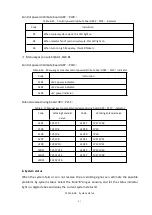
014
Gas leakage testing
Error 1
Gas leakage on solenoid valve of
manual gas console
Check the solenoid valve of
manual gas console and confirm
the connection is good and there
is clean inside the valve.
015
Gas leakage testing
Error 2
Gas pressure between gas console
solenoid valve HF box solenoid
valve get down, gas leakage in gas
circuit, and the displaying of gas
console pressure meter get down
1, Check the 4 gas hose between
gas console and HF box, to see if
there is some damage or
connectors loosen;
2, Check the 4 copper tubes
between gas console gas input
solenoid valve and rear panel, to
see if loosen or drop. If the
pressure sensor is well
connected, if leakage between
gas connectors and pressure
adjusting valve, if leakage
between gas connectors and
solenoid valve joint. Check the
installation directions.
3, Check the gas hose between 4
copper tubes in HF box and
solenoid valve,to see if loosen or
drop,if leakage between gas
connectors and solenoid valve
joint.Check the installation
directions.
Summary of Contents for FLG-200HD
Page 9: ...5 Figure 2 1 System connection diagram ...
Page 43: ...39 Figure 5 2 SQK A1 front panel function Figure 5 3 SQK B1 front panel function ...
Page 74: ...70 4 System wiring diagram Figure 7 1 System wiring diagram ...
Page 77: ...73 2 Main circuit wiring diagram 2 Figure 7 4 FLG 200HD Main circuit wiring diagram 2 ...
Page 81: ...77 6 HF striking diagram Figure 7 8 HF striking diagram ...


