


5
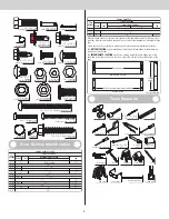
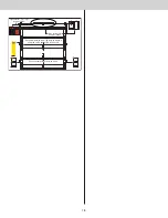
A. FLAG ANGLES (AS REQUIRED):
A1. Fully Adjustable (F.A.) Flag Angles
B. JAMB BRACKETS (AS REQUIRED):
B1. Fully Adjustable (F.A.) Jamb Brackets
C. TRACK ROLLERS (AS REQUIRED):
C1. Short Stem Track Rollers
C2. Long Stem Track Rollers
D. GRADUATED END HINGES:
D1. Single Graduated End Hinges (S.E.H.), Industry Standard
D2. Double Graduated End Hinges (D.E.H.), Industry Standard
D3. Half Center Hinge(s) (If included)
E. STACKED SECTIONS:
E1. Top Section / E2. Intermediate(s) Section
E3. Lock Section / E4. Bottom Section
F. TOP FIXTURES (AS REQUIRED):
F1. Top Fixture Bases - (L - Shaped)
F2. Top Fixture Slides - (L - Shaped)
F3. Top Fixture Assemblies
G. STRUT(S) (AS REQUIRED):
G1. 2” Strut (U-shaped) / 3” Strut (U-shaped)
H. DRAWBAR OPERATOR BRACKET (FOR TROLLEY OPERATED DOORS):
H1. Top Halve Drawbar Operator Bracket
H2. Bottom Halve Drawbar Operator Bracket
H3. Drawbar Operator Bracket (Supplied By Others)
I. TRACKS (AS REQUIRED):
I1. Left Hand and Right Hand Horizontal Track Assemblies
I2. Left Hand and Right Hand Vertical Tracks
I3. Left Hand and Right Hand Riveted Vertical Track Assemblies
I4. Left Hand and Right Hand Angle Mount Vertical Track Assemblies
J. EXTENSION SPRING ASSEMBLY (AS REQUIRED):
J1. Extension Springs
J2. Spring Restraint Cables
J3. Front Cable Lift Sheaves
J4. Rear Cable Lift Sheaves
J5. 3 Hole Clips (As Required)
J6. S-Hooks (As Required)
J7. Sheave Forks (As Required)
J8. 5/16” - 18 x 3-3/4” Eye Bolts (As Required)
J9. Counterbalance Lift Cables
J10. Hook Plates (As Required)
K. REAR BACK HANGS:
K1. Left Hand And Right Hand Rear Back Hang Assemblies
L. BOTTOM CORNER BRACKETS (AS REQUIRED):
L1. Left Hand and Right Hand Bottom Corner Brackets
M. BOTTOM WEATHER SEAL:
M1. Bottom Weather Seal (Door Width)
N. TRACK ROLLER CARRIER’S (AS REQUIRED):
N1. Track Roller Carrier’s
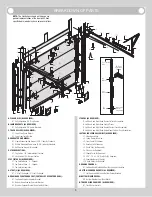
A1.
B1.
B1.
A1.
C1.
E4.
E1.
E2.
E3.
F3.
F2.
I2.
I1.
I1.
I2.
K1.
K1.
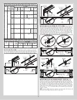
Lower hole
of hole/
slot pattern
3rd
hole set
Top of vertical
track
B1. (Fully
Adjustable
Feature)
2nd
hole set
1st
hole set
I4.
I4.
F1.
F3.
F1.
F2.
I3.
I3.
C1.
NOTE:
The illustrations shown on this page are
general representations of the door parts. Each
specific door models may have unique variations.
C2.
D1. D2.
C1.
H1.
H3.
H2.
G1.
G1.
M1.
L1.
L1.
N1.
N1.
D3.
D3.
J3.
J5.
J6.
J5.
J4.
J7.
J1.
J5.
J8.
J10.
J9.
J2.
J5.
J5.
J8.
J4.
J7.
J1.
J9.
J2.
J6.
J5.
J10.
J3.
BREAKDOWN OF PARTS


